
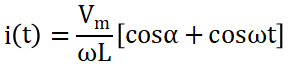
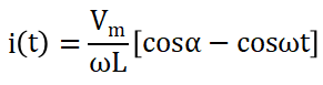
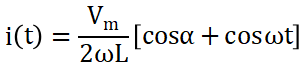
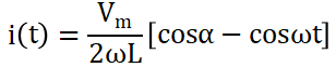
A single phase voltage source of magnitude and frequency ω (rad/s) is connected to an inductance L through an anti-parallel back-to-back pair of thyristors. The forward and reverse conducting thyristors are fired at an angle of from the positive going and negative going zero crossings of the supply voltage respectively, in each cycle.


Obtain an expression for the inductor current in each cycle for a given value of α.
The voltage drop across the thyristors, when either of them is in conclusion, may be assumed to be negligible.
Explanation Locked!
Unlock this branch to view the explanation, track, bookmark and more.
Sign in to UnlockThe incremental cost characteristics of two generators delivering 200 MW are as follows
,


For economic operation, the generations and should be


Explanation Locked!
Unlock this branch to view the explanation, track, bookmark and more.
Sign in to UnlockAn analogue electronic circuit that measures rms value of the input voltage by averaging the square of the instantaneous voltage level, responds slowly to changes in the input signal due to
Explanation Locked!
Unlock this branch to view the explanation, track, bookmark and more.
Sign in to UnlockIf an ac voltage wave is corrupted with an arbitrary number of harmonics, then the overall voltage waveform differs from its fundamental frequency component in terms of
Explanation Locked!
Unlock this branch to view the explanation, track, bookmark and more.
Sign in to UnlockA dc motor with armature resistance is fed from a step down chopper in the continuous mode, and operates at some known speed and known excitation current. The motor current rises from in the ON period of the chopper; and drops from in the OFF period of the same circuit. Both the rise and fall of the current may be assumed to be approximately linear.


What is the average power loss in the machine armature?

Explanation Locked!
Unlock this branch to view the explanation, track, bookmark and more.
Sign in to UnlockA 1.8° step, 4-pole stepper motor has a total of 40 teeth on 8 poles of stator. The number of rotor teeth for this motor will be
Explanation Locked!
Unlock this branch to view the explanation, track, bookmark and more.
Sign in to UnlockMaximum phase-lead of the compensator , is

Explanation Locked!
Unlock this branch to view the explanation, track, bookmark and more.
Sign in to UnlockA unity feedback system has open-loop transfer function

(a) Draw a rough sketch of the root locus plot; given that the complex roots of the characteristic equation move along a circle.
(b) As K increases, does the system become stable? Justify your answer.
(c) Find the value of K (if it exists) so that the damping of the complex closed loop poles is 0.3

(a)
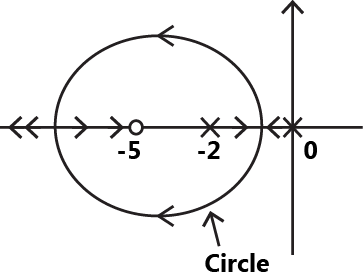
(b) As k increases. The branches of root locus move left and hence system becomes more stable.
(c) no such value of k exists such that

None of these
Explanation Locked!
Unlock this branch to view the explanation, track, bookmark and more.
Sign in to UnlockThe type of power amplifier which exhibits crossover distortion in its output is
Explanation Locked!
Unlock this branch to view the explanation, track, bookmark and more.
Sign in to UnlockA two-port device is defined by the following pair of equations:
and


Its impedance parameters are given by

Explanation Locked!
Unlock this branch to view the explanation, track, bookmark and more.
Sign in to UnlockInstrument transformers are known to introduce magnitude and phase errors in measurements. These are primarily due to
Explanation Locked!
Unlock this branch to view the explanation, track, bookmark and more.
Sign in to UnlockIn a thermal power plant, the feed water coming to the economizer is heated using
Explanation Locked!
Unlock this branch to view the explanation, track, bookmark and more.
Sign in to UnlockThe counter shown in the figure, is initially in state . With reference to the CLK input, draw waveforms for and P for the next three CLK cycles.


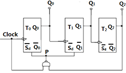
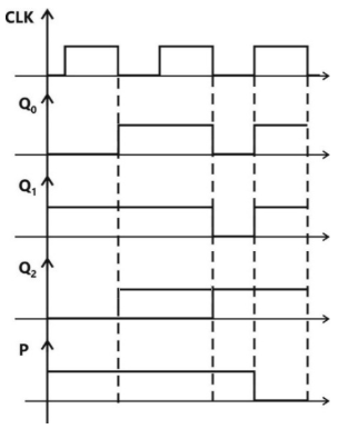
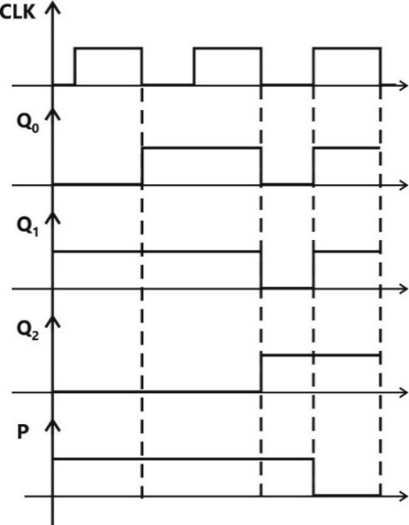
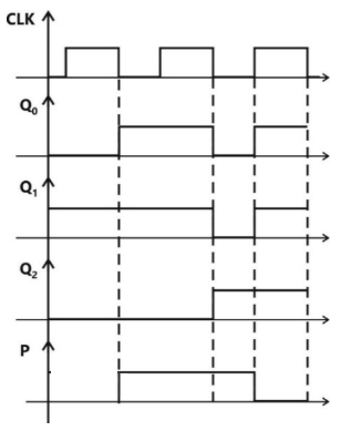
None
Explanation Locked!
Unlock this branch to view the explanation, track, bookmark and more.
Sign in to UnlockA current amplifier has an input resistance of 10Ω, an output resistance of 10kΩ and a current gain of 1000. It is feed by a current source having a source resistance of 10k Ω and its output is connected to a 10 Ω load resistance.
Explanation Locked!
Unlock this branch to view the explanation, track, bookmark and more.
Sign in to UnlockA diode whose terminal characteristics are related as , where is the reverse saturation current and is the thermal voltage , is biased at . Its dynamic resistance is:


Explanation Locked!
Unlock this branch to view the explanation, track, bookmark and more.
Sign in to UnlockTriangular PWM control, when applied to a three phase, BJT based voltage source inverter, introduces
Explanation Locked!
Unlock this branch to view the explanation, track, bookmark and more.
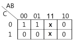
Sign in to UnlockThe minimal product of sums function described by the K-map
Explanation Locked!
Unlock this branch to view the explanation, track, bookmark and more.
Sign in to UnlockA step down chopper operates from a dc voltage source and feeds a dc motor armature with a back emf . From oscilloscope traces, it is found that the current increases for time, falls to zero over time, and remains zero for time, in every chopping cycle. Then the average dc voltage across the freewheeling diode is:


Explanation Locked!
Unlock this branch to view the explanation, track, bookmark and more.
Sign in to UnlockRatio of the rotor reactance X to the rotor resistance R for a two-phase servomotor
Explanation Locked!
Unlock this branch to view the explanation, track, bookmark and more.
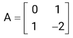
Sign in to UnlockConsider the state equation

Given:

(a) Find a set of states and such that


(b) From , find the matrix A.

Data is insufficient to determine and


Explanation Locked!
Unlock this branch to view the explanation, track, bookmark and more.
Sign in to UnlockIn a 3-bus system, Gauss load flow method is to be used for finding the switched capacitor compensation required to maintain the voltage at bus 2 equal to 1.0p.u. the data for the system is as follows
Line data : Neglect line charging.

Bus data :
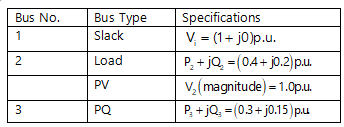
All data are on common base values.
None
Explanation Locked!
Unlock this branch to view the explanation, track, bookmark and more.
Sign in to UnlockA three phase voltage source inverter supplies a purely inductive three phase load. Upon Fourier analysis, the output voltage waveform is found to have an n-th order harmonic of magnitude times that of the fundamental frequency component. The load current would then have an n-th order harmonic of magnitude


Zero
times the fundamental frequency component
times the fundamental frequency component

times the fundamental frequency component

Explanation Locked!
Unlock this branch to view the explanation, track, bookmark and more.
Sign in to UnlockFeedback control systems are
Explanation Locked!
Unlock this branch to view the explanation, track, bookmark and more.
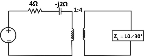
Sign in to UnlockThe circuit shown in figure is equivalent to a load of
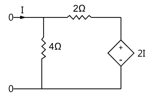


4 ohms
2 ohms
Explanation Locked!
Unlock this branch to view the explanation, track, bookmark and more.
Sign in to UnlockA dual slope analog-to-digit converters uses an N-bit counter. When the input signal is being integrated, the counter is allowed to count up to a value


Equal to
Equal to

Proportional to
Inversely proportional to
Explanation Locked!
Unlock this branch to view the explanation, track, bookmark and more.
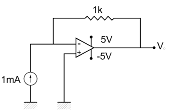
Sign in to UnlockIn the circuit of fig, the value of the base current will be

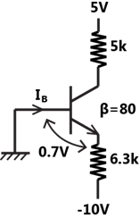
Explanation Locked!
Unlock this branch to view the explanation, track, bookmark and more.
Sign in to UnlockThe characteristic equation of a feedback control system is:

The number of roots in the right half of s-plane are :
Explanation Locked!
Unlock this branch to view the explanation, track, bookmark and more.
Sign in to UnlockA voltage waveform is applied across a 1H inductor for , with initial current through it being zero. The current through the inductor for is given by


Explanation Locked!
Unlock this branch to view the explanation, track, bookmark and more.
Sign in to UnlockWhich one of the following is not a vectored interrupt?
Explanation Locked!
Unlock this branch to view the explanation, track, bookmark and more.
Sign in to UnlockFor given base voltage and base volt-amperes, the per unit impedance value of an element is x. What will be the per unit impedance value of this element when the voltage and volt ampere bases are both doubled?
Explanation Locked!
Unlock this branch to view the explanation, track, bookmark and more.
Sign in to UnlockA transmission line has equal voltages at the two ends, maintained constant by two sources. A third source is to be provided to maintain constant voltage (equal to end voltages) at either the midpoint of the line or at 75% of the distance from the sending end. Then the maximum power transfer capabilities of the line in the original case and the other two cases respectively will be in the following ratios.:
1 : 1 : 1

1 : 2 : 4
1 : 4 : 16
Explanation Locked!
Unlock this branch to view the explanation, track, bookmark and more.
Sign in to UnlockOpen-loop transfer function of a unity-feedback system is:

Given : when


(a) Determine the phase margin when

(b) Comment in one sentence on the effect of dead time on the stability of the system
(c) Determine the maximum value of dead time for the closed-loop system to be stable

(a) Phase margin

(b) Phase margin reduces and stability decreases
(b) Phase margin reduces and stability increases
(c)

Explanation Locked!
Unlock this branch to view the explanation, track, bookmark and more.
Sign in to UnlockThe severity of line-to-ground and three phase faults at the terminals of an unloaded synchronous generator is to be same. If the terminal voltage is 1.0 p.u. and , for the alternator, then the required inductive reactance for neutral grounding is:


Explanation Locked!
Unlock this branch to view the explanation, track, bookmark and more.
Sign in to UnlockA synchronous generator, having a reactance of 0.15p.u, is connected to an infinite bus through two identical parallel transmission lines having reactance of 0.3p.u. each. In steady state, the generator is delivering 1p.u. Power to the infinite bus. For a three-phase fault at the receiving end of one line, calculate the rotor angle at the end of first time step of 0.05 seconds. Assume the voltage behind transient reactance for the generator as 1.1p.u. and infinite bus voltage as 1.0p.u.

When breaker clears the fault at the end of an interval, Accelerating power will be considered as the average of before and after faults.

When breaker clears the fault at the middle of an interval then we will have to consider the accelerating power same as that of beginning of that interval, i.e.

Explanation Locked!
Unlock this branch to view the explanation, track, bookmark and more.
Sign in to UnlockFor the configuration shown in figure, the breaker connecting a large system to bus 2 is initially open. The system 3-phase fault level at bus-3 under this condition is not known. After closing the system breaker, the 3-phase fault level at bus 1 was found to be 5 p.u. What will be the new 3-phase fault level at system bus 3 after the interconnection? All unit values are on common bases. Per fault load current are neglected and pre fault voltages are assumed to be 1.0 p.u. at all buses.

Explanation Locked!
Unlock this branch to view the explanation, track, bookmark and more.
Sign in to UnlockAn electron with velocity u is placed an electric field E and magnetic field B. the force experienced by the electron is given by
–eE


Explanation Locked!
Unlock this branch to view the explanation, track, bookmark and more.
Sign in to Unlock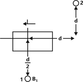
(a) For the construction of a suitable Gaussian surface, the capacitance of a spherical capacitor consisting of two concentric shells of radii a and b is given by = ?
(b) A current I in the short conducting element shown in fig produces a flux density at point 1.

Determine the magnitude and the direction of
the flux density vector at point 2.
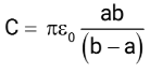
Where is the free space permittivity


Where is the free space permittivity
Explanation Locked!
Unlock this branch to view the explanation, track, bookmark and more.
Sign in to UnlockA three phase semi-converter feeds the armature of a separately excited dc motor, supplying a non-zero torque. For steady state operation, the motor armature current is found to drop to zero at certain instances of time. At such instances, the voltage assumes a value that is
Explanation Locked!
Unlock this branch to view the explanation, track, bookmark and more.
Sign in to UnlockFor perfectly balanced operation a certain three phase ac power electronic circuit generates odd harmonic currents of order five and seven in the three phases of the ac mains. Identify which of these harmonics form a positive-sequence system, and which form a negative – sequence system.
Explanation Locked!
Unlock this branch to view the explanation, track, bookmark and more.
Sign in to UnlockIn an inverse definite minimum time, electromagnetic type over-current relay the minimum time feature is achieved because of
Explanation Locked!
Unlock this branch to view the explanation, track, bookmark and more.
Sign in to UnlockA thyristorised , three phase, fully controlled converter feeds a dc load that draws a constant current. Then the input ac line current to the converter has
Explanation Locked!
Unlock this branch to view the explanation, track, bookmark and more.
Sign in to UnlockIn a 3-step distance protection, the reach of the three zones of the relay at the beginning of the first line typically extends up to
Explanation Locked!
Unlock this branch to view the explanation, track, bookmark and more.
Sign in to UnlockThe plug setting of a negative sequence relay is 0.2A. The current transformer ratio is 5:1. The minimum value of line-to-line fault current for the operation of the relay is
1A

1.732A

Explanation Locked!
Unlock this branch to view the explanation, track, bookmark and more.
Sign in to UnlockA unity feedback system has open loop transfer function G(s). The steady-state error is zero for
Explanation Locked!
Unlock this branch to view the explanation, track, bookmark and more.
Sign in to UnlockA linear time-invariant system initially at rest, when subjected to a unit-step input, gives a response,. The transfer function of the system is:


Explanation Locked!
Unlock this branch to view the explanation, track, bookmark and more.
Sign in to UnlockThe impedance seen by the source in the circuit in figure, is given by


Explanation Locked!
Unlock this branch to view the explanation, track, bookmark and more.
Sign in to UnlockA unity feedback system has open loop transfer function. The peak overshoot in the step-input response of the system is approximately equal to:

Explanation Locked!
Unlock this branch to view the explanation, track, bookmark and more.
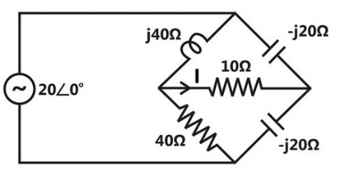
Sign in to UnlockPredict the current I in figure in response to a voltage of . The impedance values are given in ohms. Use the thevenin’s theorem.

Explanation Locked!
Unlock this branch to view the explanation, track, bookmark and more.
Sign in to UnlockThe phase sequence of a three-phase alternator will reverse if
Explanation Locked!
Unlock this branch to view the explanation, track, bookmark and more.
Sign in to UnlockA single-phase, 2000V alternator has armature resistance and reactance of 0.8 ohms and 4.94 ohms respectively. The voltage regulation of the alternator at 100A load at 0.8 leading power-factor is:
Explanation Locked!
Unlock this branch to view the explanation, track, bookmark and more.
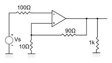
Sign in to UnlockThe circuit shown is fig. uses an ideal op-amp working +5V and -5V power supplies. The output voltage is equal to

Explanation Locked!
Unlock this branch to view the explanation, track, bookmark and more.
Sign in to UnlockA 2300V, 3-phase synchronous motor driving a pump is provided with a line ammeter and a field rheostat. When the rheostat is adjusted such that the ac line current is minimum, the armature reads 8.8A.
(a) What is the power being delivered to the pump, neglecting losses?
(b) How should the rheostat be adjusted so that the motor operates at 0.8 leading power factor?
(c) How many KVARs is the motor supply to the system at this new power factor?
Explanation Locked!
Unlock this branch to view the explanation, track, bookmark and more.
Sign in to UnlockThe compensating winding in a dc machine
Explanation Locked!
Unlock this branch to view the explanation, track, bookmark and more.
Sign in to UnlockThe feedback factor for the circuit shown in fig. is:


Explanation Locked!
Unlock this branch to view the explanation, track, bookmark and more.
Sign in to UnlockA permanent magnet dc commutator motor has a no load speed of 6000 rpm when connected to a 120V dc supply. The armature resistance is 2.5 ohms and other losses may be neglected. The speed of the motor with supply voltage of 60V developing a torque 0.5 Nm, is:
Explanation Locked!
Unlock this branch to view the explanation, track, bookmark and more.
Sign in to UnlockAn active filter consisting of an op-amp, resistors and two capacitors of value C each, has a transfer function


Where

If and , determine the center frequency , gain and the Q of the filter.


Explanation Locked!
Unlock this branch to view the explanation, track, bookmark and more.
Sign in to UnlockThe two wattmeter method is used to measure active power on a three phase, three wire system. If the phase voltage is unbalanced, then the power reading is:
Explanation Locked!
Unlock this branch to view the explanation, track, bookmark and more.
Sign in to UnlockA belt driven dc shunt generator runs at 1500 rpm delivering 10kW, at 220V bus bars. The belt breaks, following which the machine operates as a motor drawing 2kW power. What will be its speed as a motor? The armature and field resistances are 0.25 ohms and 55 ohms respectively. Ignore armature reaction and assume the contact drop at each brush to be 1V.
Explanation Locked!
Unlock this branch to view the explanation, track, bookmark and more.
Sign in to UnlockA three-phase load operates with balanced voltages applied to its terminals, and draws balanced currents. The potential coil of a moving coil wattmeter is connected from R to Y terminals of the load. The current coil of the meter is connected in series with phase B. Then the quantity indicated by this wattmeter is proportional
Explanation Locked!
Unlock this branch to view the explanation, track, bookmark and more.
Sign in to UnlockA 240V dc series motor takes 40A when giving its rated output at 1500 rpm. Its resistance is 0.3 ohms. The value of resistance which must be added to obtain rated torque at 1000 rpm is:
Explanation Locked!
Unlock this branch to view the explanation, track, bookmark and more.
Sign in to UnlockA 3-phase, 4-pole squirrel cage induction motor has 36 stator and 28 rotor slots. The number of phases in the rotor is:
Explanation Locked!
Unlock this branch to view the explanation, track, bookmark and more.
Sign in to UnlockThe power input to a 415V, 50 Hz, 6 pole, 3-phase induction motor running at 975 rpm is 40 kW. The stator losses are 1 kW and friction and windage losses total 2kW. The efficiency of the motor is
Explanation Locked!
Unlock this branch to view the explanation, track, bookmark and more.
Sign in to UnlockA three phase, wound rotor induction motor is to be operated with slip energy recovery in the constant torque mode, when it delivers an output power at slip s. Then theoretically, the maximum power that is available for recovery at the rotor terminals, is equal to


Explanation Locked!
Unlock this branch to view the explanation, track, bookmark and more.
Sign in to UnlockIn a constant voltage transformer (CVT), the output voltage remains constant due to
Explanation Locked!
Unlock this branch to view the explanation, track, bookmark and more.
Sign in to UnlockA 230V, 20 hp, 60 Hz, 6-pole, 3-phase induction motor driving a constant torque load at rated frequency, rated voltage and rated horse-power, has a speed of 1175 rpm and an efficiency of 92.1%. Determine the new operating speed if a system disturbance causes 10% drop in voltage and 6% drop in frequency. Assume that friction, windage and stray power losses remain constant.
Explanation Locked!
Unlock this branch to view the explanation, track, bookmark and more.
Sign in to UnlockA 3-phase delta/star transformer is supplied at 6000V on the delta-connected side. The terminal voltage on the secondary side when supplying full load as 0.8 lagging power-factor is 415V. The equivalent resistance and reactance drops for the transformer are 1% and 5% respectively. The turns ratio of the transformer is:
Explanation Locked!
Unlock this branch to view the explanation, track, bookmark and more.
Sign in to UnlockIn a single-phase, three –winding transformer, the turns ratio for primary: secondary : tertiary windings is 20:4:1. With the lagging currents of 50A at a power factor of 0.6 in the tertiary winding, find the magnitude of primary current and power-factor.
Explanation Locked!
Unlock this branch to view the explanation, track, bookmark and more.
Sign in to UnlockOut of the considerations (i) and (iv) listed below
(i) No distance limitation related to steady state stability
(ii) No reactive power requirement from the system at the two terminals
(iii) No substantial effect fault level of the two systems at the terminals in spite of the interconnection
(iv) No corona problems
The considerations, which constitute advantage of HVDC transmission, are
Explanation Locked!
Unlock this branch to view the explanation, track, bookmark and more.
Sign in to UnlockThe corona loss on a particular system at 50 Hz is 1kW/km per phase. The corona loss at 60 Hz would be
Explanation Locked!
Unlock this branch to view the explanation, track, bookmark and more.
Sign in to UnlockA 275kV, 3-phase, 50 Hz, 400km lossless line has following parameters:
, line charging susceptance micro-Siemens/km


(a) Calculate the receiving end voltage on open circuit using justifiable assumptions.
(b) What load at the receiving end will result in a flat voltage profile on the line?
(c) If the flat voltage profile is to be achieved at 1.2 times the loading in (b), what will be the nature and quantum of uniformly distributed compensation required
Explanation Locked!
Unlock this branch to view the explanation, track, bookmark and more.
Sign in to Unlock