
The digital circuit using two inverters shown in figure will act as

Explanation Locked!
Unlock this branch to view the explanation, track, bookmark and more.
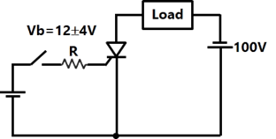
Sign in to UnlockThe triac circuit shown in figure controls the ac output power to the resistive load. The peak power dissipation in the load is

Explanation Locked!
Unlock this branch to view the explanation, track, bookmark and more.
Sign in to UnlockA dc potentiometer is designed to measure up to about 2V with a slide wire of 300 mm. A standard cell of EMF 1.18 V obtains balance at 600 mm. A test cell is seen to obtain balance at 680 mm. The EMF of the test cell is
Explanation Locked!
Unlock this branch to view the explanation, track, bookmark and more.
Sign in to UnlockIn the thermal power plants, the pressure in the working fluid cycle is developed by
Explanation Locked!
Unlock this branch to view the explanation, track, bookmark and more.
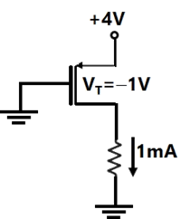
Sign in to UnlockThe value of R for which the PMOS transistor in figure will be biased in linear region is


Explanation Locked!
Unlock this branch to view the explanation, track, bookmark and more.
Sign in to UnlockFor a given stepper motor, the following torque has the highest numerical value.
Explanation Locked!
Unlock this branch to view the explanation, track, bookmark and more.
Sign in to UnlockFor harnessing low variable water heads, the suitable hydraulic turbine with high percentage of reaction and runner adjustable vanes is
Explanation Locked!
Unlock this branch to view the explanation, track, bookmark and more.
Sign in to UnlockA rotating electrical machine having its self-inductances of both the stator and the rotor windings, independent of the rotor position will be definitely not develop
Explanation Locked!
Unlock this branch to view the explanation, track, bookmark and more.
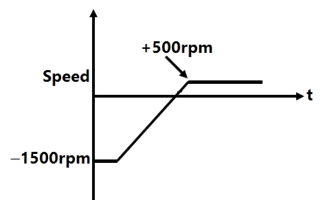
Sign in to UnlockA variable speed drive rated for 1500 rpm, 40 Nm is reversing under no load. Figure shows the reversing torque and the speed during the transient. The moment of inertia of the drive is


Explanation Locked!
Unlock this branch to view the explanation, track, bookmark and more.
Sign in to UnlockA 50 Hz, bar primary CT has a secondary with 500 turns. The secondary supplies 5A current into a purely resistive burden of 1Ω. The magnetizing ampere-turns is 200. The phase angle between the primary and secondary current is
Explanation Locked!
Unlock this branch to view the explanation, track, bookmark and more.
Sign in to UnlockThe simplified form of the Boolean expression can be written as


Explanation Locked!
Unlock this branch to view the explanation, track, bookmark and more.
Sign in to UnlockThe RMS value of the periodic waveform given in figure is
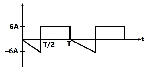


1.5 A
Explanation Locked!
Unlock this branch to view the explanation, track, bookmark and more.
Sign in to UnlockA 50 Hz, bar primary CT has a secondary with 500 turns. The secondary supplies 5A current into a purely resistive burden of 1W. The magnetizing ampere-turns is 200. The core flux in the CT, under the given operating condition is
Explanation Locked!
Unlock this branch to view the explanation, track, bookmark and more.
Sign in to UnlockFor a 1.8°, 2-phase bipolar stepper motor, the stepping rate is 100steps/second. The rotational speed of the motor in rpm is
Explanation Locked!
Unlock this branch to view the explanation, track, bookmark and more.
Sign in to UnlockA CRO probe has an impedance of 500 kΩ in parallel with a capacitance of 10pF. The probe is used to measure the voltage between P and Q as shown in figure. The measured voltage will be

Explanation Locked!
Unlock this branch to view the explanation, track, bookmark and more.
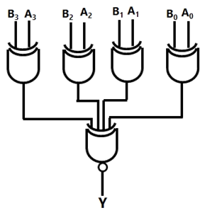
Sign in to UnlockA digital circuit, which compares two numbers, is shown in figure. To get output Y = 0, choose one pair of correct input numbers.

Explanation Locked!
Unlock this branch to view the explanation, track, bookmark and more.
Sign in to UnlockThe current through the Zener diode in figure is

Explanation Locked!
Unlock this branch to view the explanation, track, bookmark and more.
Sign in to UnlockThe circuit in figure shows a full-wave rectifier. The input voltage is 230V (RMS) single-phase ac. The peak reverse voltage across the diodes D1 and D2 is
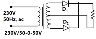

100 V
V

50 V
Explanation Locked!
Unlock this branch to view the explanation, track, bookmark and more.
Sign in to UnlockAssuming that the diodes are ideal in figure, the current in is

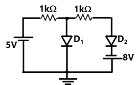
Explanation Locked!
Unlock this branch to view the explanation, track, bookmark and more.
Sign in to UnlockThe digital circuit shown in figure generates a modified clock pulse at the output. Choose the correct output waveform form the options given below.

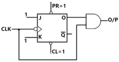


Explanation Locked!
Unlock this branch to view the explanation, track, bookmark and more.
Sign in to UnlockFor a tachometer if θ(t) is the rotor displacement is radians, e(t) is the output voltage and Kt is the tachometer constant in V/rad/sec, then the transfer function, will be


Explanation Locked!
Unlock this branch to view the explanation, track, bookmark and more.
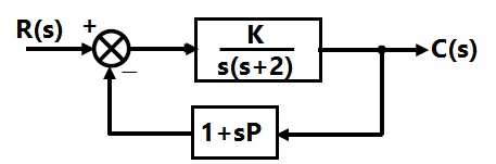
Sign in to UnlockFor the block diagram shown in figure, the transfer function is equal to

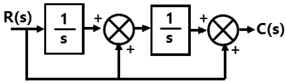


Explanation Locked!
Unlock this branch to view the explanation, track, bookmark and more.
Sign in to UnlockFor the equation, , the number of roots in the left half of s-plane will be

Explanation Locked!
Unlock this branch to view the explanation, track, bookmark and more.
Sign in to UnlockThe Z matrix of a 2-port network as given by

The element of the corresponding Y matrix of the same network is given by

Explanation Locked!
Unlock this branch to view the explanation, track, bookmark and more.
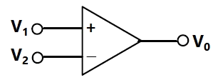
Sign in to UnlockThe voltage comparator shown in figure can be used in as
Explanation Locked!
Unlock this branch to view the explanation, track, bookmark and more.
Sign in to UnlockFigure shows a chopper operating from a 100 V dc input. The duty ratio of the main switch S is 0.8. The load is sufficiently inductive so that the load current is ripple free. The average current through the diode D under steady state is

Explanation Locked!
Unlock this branch to view the explanation, track, bookmark and more.
Sign in to UnlockThe state variable description of a linear autonomous system is X = AX, where X is the two dimensional state vector and A is the system matrix given by
. The roots of the characteristic equation are

Explanation Locked!
Unlock this branch to view the explanation, track, bookmark and more.
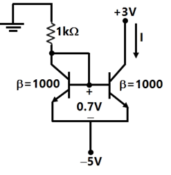
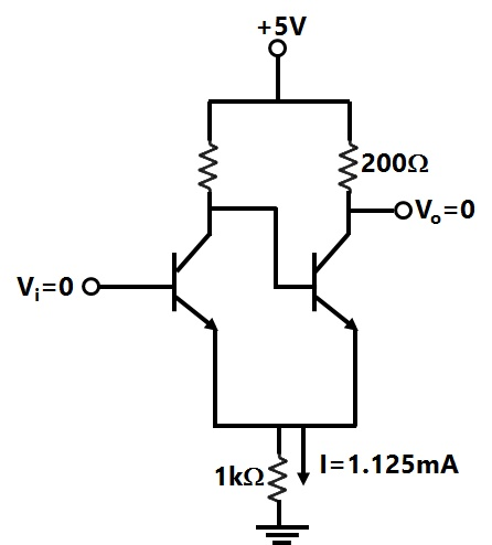
Sign in to UnlockTwo perfectly matched silicon transistors are connected as shown in figure. The value of the current I is
Explanation Locked!
Unlock this branch to view the explanation, track, bookmark and more.
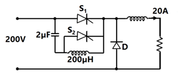
Sign in to UnlockFigure shows a chopper. The device S1 is the main switching device. S2 is the auxiliary commutation device. S1 is rated for 400V, 60A. S2 is rated for 400V, 30 A. the load current is 20 A. The main device operates with a duty ratio of 0.5. The peak current through S1 is
Explanation Locked!
Unlock this branch to view the explanation, track, bookmark and more.
Sign in to UnlockThe Nyquist plot of loop transfer function G(s) H(s) of a closed loop control system passes through the point (−1, j0) in the G(s) H(s) plane. The phase margin of the system is
Explanation Locked!
Unlock this branch to view the explanation, track, bookmark and more.
Sign in to UnlockIf the following program is executed in a microprocessor, the number of instruction cycles it will take from START TO HALT is
START MVI A, 14 H : Move 14 H to register A
SHIFT RLC : Rotate left without carry
JNZ SHIFT : Jump on non-zero to
SHIFT
HALT
Explanation Locked!
Unlock this branch to view the explanation, track, bookmark and more.
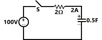
Sign in to UnlockIn figure, the capacitor initially has a charge of 10 Coulomb. The current in the circuit one second after the switch S is closed will be
Explanation Locked!
Unlock this branch to view the explanation, track, bookmark and more.
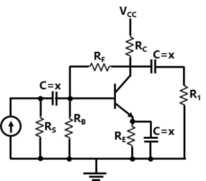
Sign in to UnlockThe feedback used in the circuit shown in figure can be classified as
Explanation Locked!
Unlock this branch to view the explanation, track, bookmark and more.
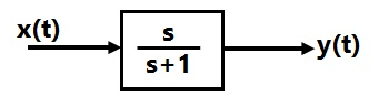
Sign in to UnlockIn the system shown in figure, the input x(t)=sin t. In the steady-state, the response y(t) will be


Explanation Locked!
Unlock this branch to view the explanation, track, bookmark and more.
Sign in to UnlockA bipolar junction transistor (BJT) is used as a power control switch by biasing it in the cut-off region (OFF state) or in the saturation region (ON state). In the ON state, for the BJT
Explanation Locked!
Unlock this branch to view the explanation, track, bookmark and more.
Sign in to UnlockA 50 Hz, 4-pole, 500 MVA, 22 kV turbo-generator is delivering rated megavolt amperes at 0.8 power factor. Suddenly a fault occurs reducing is electric power output by 40%. Neglect losses and assume constant power input to the shaft. The accelerating torque in the generator in MNm at the time of the fault will be
Explanation Locked!
Unlock this branch to view the explanation, track, bookmark and more.
Sign in to UnlockThe RMS value of the resultant current in a wire which carries a dc current of 10 A and a sinusoidal alternating current of peak value 20 A is
Explanation Locked!
Unlock this branch to view the explanation, track, bookmark and more.
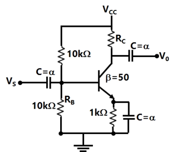
Sign in to UnlockThe trans-conductance of the transistor shown in figure is 10mS. The value of the input resistance is


Explanation Locked!
Unlock this branch to view the explanation, track, bookmark and more.
Sign in to UnlockThe open loop transfer function of a unity feedback control system is given as

The value of ‘a’ to give a phase margin of 45° is equal to
Explanation Locked!
Unlock this branch to view the explanation, track, bookmark and more.
Sign in to UnlockThe inductance of a long solenoid of length 1000 mm wound uniformly with 3000 turns on a cylindrical paper tube of 60mm diameter is
Explanation Locked!
Unlock this branch to view the explanation, track, bookmark and more.
Sign in to UnlockIn figure, the value of the source voltage is
Explanation Locked!
Unlock this branch to view the explanation, track, bookmark and more.
Sign in to UnlockIn the Schmitt trigger circuit shown in figure, if , the output logic low level is


Explanation Locked!
Unlock this branch to view the explanation, track, bookmark and more.
Sign in to UnlockThe triggering circuit of a thyristor is shown in figure. The thyristor requires a gate current of 10 mA, for guaranteed turn-on. The value of R required for the thyristor to turn on reliably under all conditions of variation is

Explanation Locked!
Unlock this branch to view the explanation, track, bookmark and more.
Sign in to UnlockA MOSFET rated for 15 A, carries a periodic current as shown in figure. The ON state resistance of the MOSFET is 0.15Ω. The average ON state loss in the MOSFET is
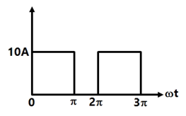
Explanation Locked!
Unlock this branch to view the explanation, track, bookmark and more.
Sign in to UnlockIn figure, Ra, Rb and Rc are 20Ω, 10Ω and 10Ω respectively. The resistance R1, R2 and R3 in Ω of an equivalent star-connection are
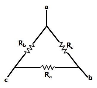
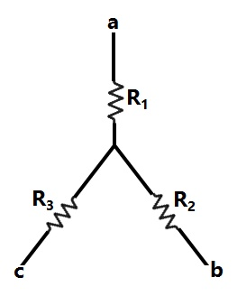
Explanation Locked!
Unlock this branch to view the explanation, track, bookmark and more.
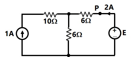
Sign in to UnlockIn figure, the value of resistance R in Ω is
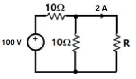
Explanation Locked!
Unlock this branch to view the explanation, track, bookmark and more.
Sign in to UnlockA parallel plate capacitor is shown in figure. It is made of two square metal plates of 400 mm side. The 14 mm space between the plates is filled with two layers of dielectrics of , 6 mm thick and , 8 mm thick. Neglecting fringing of fields at the edges the capacitance is


Explanation Locked!
Unlock this branch to view the explanation, track, bookmark and more.
Sign in to UnlockThe transmission line distance protection relay having the property of being inherently directional is
Explanation Locked!
Unlock this branch to view the explanation, track, bookmark and more.
Sign in to UnlockA 3-phase generator rated at 110MVA, 11 kV is connected through circuit breakers to a transformer. The generator is having direct axis sub-transient reactance, transient reactance 26% and synchronous reactance =130%. The generator is operating at no load and rated voltage when a three phase short circuit fault occurs between the breakers and the transformer. The magnitude of initial symmetrical rims current in the breakers will be


Explanation Locked!
Unlock this branch to view the explanation, track, bookmark and more.
Sign in to UnlockA 3-phase transmission line supplies Δ-connected load Z. The conductor ‘c’ of the line develops an open circuit fault as shown in figure. The currents in the lines are as shown on the diagram. The positive sequence current component in line ‘a’ will be
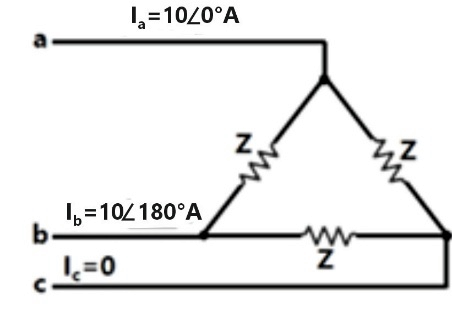


Explanation Locked!
Unlock this branch to view the explanation, track, bookmark and more.
Sign in to UnlockA 500 MVA, 50 Hz, 3-phase turbo-generator produces power at 22 kV. Generator is Y-connected and its neutral is solidly grounded. Their sequence reactance are and . It is operating at rated voltage and disconnected from the rest of the system (no load). The magnitude of the sub-transient line current for single line ground fault at the generator terminals in p.u will be


Explanation Locked!
Unlock this branch to view the explanation, track, bookmark and more.
Sign in to UnlockThe circuit in figure shows a 3-phase half-wave rectifier. The source is a symmetrical, 3-phase four-wire system. The line-to-line voltage of the source is 100 V. The supply frequency is 400 Hz. The ripple frequency at the output is
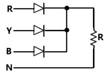
Explanation Locked!
Unlock this branch to view the explanation, track, bookmark and more.
Sign in to UnlockConsider the function , where F(s) is the Laplace transform of the function f(t). The initial value of f(t) is equal to

5


0
Explanation Locked!
Unlock this branch to view the explanation, track, bookmark and more.
Sign in to UnlockThe block diagram of a closed loop control system is given by figure. The values of K and P such that the system has a damping ratio of 0.7 and an un-damped natural frequency of 5rad/sec, are respectively equal to

Explanation Locked!
Unlock this branch to view the explanation, track, bookmark and more.
Sign in to UnlockA single-phase half wave controlled rectifier is driving a separately excited dc motor. The dc motor has a back emf constant of 0.5 V/rpm. The armature current is 5A without any ripple. The armature resistance is 2Ω.
The converter is working from a 230 V, single-phase ac source with a firing angle of 30°. Under this operating condition, the speed of the motor will be
Explanation Locked!
Unlock this branch to view the explanation, track, bookmark and more.
Sign in to UnlockThe unit impulse response of a second order under-damped system starting from rest is given by

The steady-state value of the unit step response of the system is equal to
Explanation Locked!
Unlock this branch to view the explanation, track, bookmark and more.
Sign in to UnlockIn the figure the value of Z in Figure, which is most appropriate to cause parallel resonance at 500 Hz, is
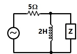
Explanation Locked!
Unlock this branch to view the explanation, track, bookmark and more.
Sign in to UnlockTotal instantaneous power supplied by a 3-phase ac supply to a balanced R-L load is
Explanation Locked!
Unlock this branch to view the explanation, track, bookmark and more.
Sign in to UnlockIn figure, the admittance values of the elements in Siemens are
respectively.

The value of I as a phasor when the voltage E across the elements isis

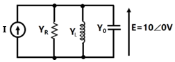
Explanation Locked!
Unlock this branch to view the explanation, track, bookmark and more.
Sign in to UnlockThe synchronous speed for the seventh space harmonic mmf wave of a 3-phase, 8 pole, 50 Hz induction machine is
Explanation Locked!
Unlock this branch to view the explanation, track, bookmark and more.
Sign in to UnlockTwo 3-phases, Y-connected alternators are to be paralleled to a set of common bus bars. The armature has a per phase synchronous reactance of 1.7Ω and negligible armature resistance. The line voltage of the first machines is adjusted to 3300 V and that of the second machine is adjusted to 3200 V. the machine voltages are in phase at the instant they are paralleled. Under this condition, the synchronizing current per phase will be
Explanation Locked!
Unlock this branch to view the explanation, track, bookmark and more.
Sign in to UnlockIn the active filter circuit shown in figure, if Q=1, a pair of poles will be realized with equal to


Explanation Locked!
Unlock this branch to view the explanation, track, bookmark and more.
Sign in to UnlockA 400V, 50 kVA, 0.8 pf leading Δ-connected, 50 Hz synchronous machine has a synchronous reactance of 2Ω and negligible armature resistance. The friction and windage losses are 2kW and the core loss is 0.8 kW. The shaft is supplying 9kW load at a power factor of 0.8 leading. The line current drawn is
Explanation Locked!
Unlock this branch to view the explanation, track, bookmark and more.
Sign in to UnlockA 500 MW 3-phase Y-connected synchronous generator has a rated voltage of 21.5 kV at 0.85 pf. The line current when operating at full load rated conditions will be
Explanation Locked!
Unlock this branch to view the explanation, track, bookmark and more.
Sign in to UnlockThe circuit in figure is used to measure the power consumed by the load. The current coil and the voltage coil of the wattmeter have 0.02Ω and 1000Ω resistances respectively. The measured power compared to the load power will be
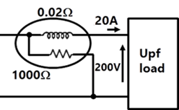
Explanation Locked!
Unlock this branch to view the explanation, track, bookmark and more.
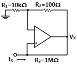
Sign in to UnlockThe input resistance of the circuit in figure is


Explanation Locked!
Unlock this branch to view the explanation, track, bookmark and more.
Sign in to UnlockThe following motor definitely has a permanent magnet rotor
Explanation Locked!
Unlock this branch to view the explanation, track, bookmark and more.
Sign in to UnlockFor a linear electromagnetic circuit, the following statement is true.
Explanation Locked!
Unlock this branch to view the explanation, track, bookmark and more.
Sign in to UnlockA hydraulic turbine having rated speed of 250 rpm is connected to a synchronous generator. In order to produce power at 50 Hz, the number of poles required in the generator are
Explanation Locked!
Unlock this branch to view the explanation, track, bookmark and more.
Sign in to UnlockA galvanometer with a full scale current of 10mA has a resistance of 1000Ω. The multiplying power (the ratio of measured current to galvanometer current) of a 100Ω shunt with this galvanometer is
Explanation Locked!
Unlock this branch to view the explanation, track, bookmark and more.
Sign in to UnlockA moving coil of a meter has 100 turns, and a length and depth of 10 mm and 20 mm respectively. It is positioned in a uniform radial flux density of 200mT. The coil carries a current of 50mA. The torque on the coil is
Explanation Locked!
Unlock this branch to view the explanation, track, bookmark and more.
Sign in to UnlockThe armature resistance of a permanent magnet dc motor is 0.8Ω. At no load, the motor draws 1.5 A from a supply voltage of 25 V and runs at 1500 rpm. The efficiency of the motor while it is operating on load at 1400 rpm drawing a current of 3.5 A form the same source will be
Explanation Locked!
Unlock this branch to view the explanation, track, bookmark and more.
Sign in to UnlockA 8 poles, DC generator has a simplex wave-wound armature containing 32 coils of 6 turns each. Its flux per pole is 0.06 Wb. The machine is running at 250 rpm. The induced armature voltage is
Explanation Locked!
Unlock this branch to view the explanation, track, bookmark and more.
Sign in to UnlockA dc A-h meter is rated for 15 A, 250V. The meter constant is 14.4 A-sec/rev. The meter constant at rated voltage may be expressed as
Explanation Locked!
Unlock this branch to view the explanation, track, bookmark and more.
Sign in to UnlockThe type of single-phase induction motor having the highest power factor at full load is
Explanation Locked!
Unlock this branch to view the explanation, track, bookmark and more.
Sign in to UnlockThe direction of rotation of a 3-phase induction motor is clockwise when it is supplied with 3-phase sinusoidal voltage having phase sequence A-B-C. For counter clockwise rotation of the motor, the phase sequence of the power supply should be
Explanation Locked!
Unlock this branch to view the explanation, track, bookmark and more.
Sign in to UnlockA moving iron ammeter produces a full-scale torque of 240 µNm with a deflection of 120° at a current of 10 A. The rate of change of self inductance (µH/radian) of the instrument at full scale is?
Explanation Locked!
Unlock this branch to view the explanation, track, bookmark and more.
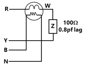
Sign in to UnlockA single-phase load is connected between R and Y terminals of a 415 V, symmetrical, 3-phase, 4-wire system with phase sequence RYB. A wattmeter is connected in the system as shown in figure. The power factor of the load is 0.8 lagging. The wattmeter will read
Explanation Locked!
Unlock this branch to view the explanation, track, bookmark and more.
Sign in to UnlockA single-phase, 230 V, 50 Hz, 4 pole, capacitor-start induction motor has the following stand still impedances
Main winding =6.0 + j4.0Ω

Auxiliary winding = 8.0 + j6.0Ω

The value of the starting capacitor required to produce 90° phase difference between the currents in the main and auxiliary windings will be
Explanation Locked!
Unlock this branch to view the explanation, track, bookmark and more.
Sign in to UnlockA 400V, 15 kW, 4 poles, 50 Hz, Y-connected induction motor has full load slip of 4%. The output torque of the machine at full load is
Explanation Locked!
Unlock this branch to view the explanation, track, bookmark and more.
Sign in to UnlockA 500 kVA, 3-phase transformer has iron loses of 300 W and full load copper losses of 600 W. The percentage load at which the transformer is expected to have maximum efficiency
Explanation Locked!
Unlock this branch to view the explanation, track, bookmark and more.
Sign in to UnlockA 50 kVA, 3300/230V single-phase transformer is connected as an autotransformer shown in figure. The nominal rating of the autotransformer will be

Explanation Locked!
Unlock this branch to view the explanation, track, bookmark and more.
Sign in to UnlockThe resistance and reactance of a 100 kVA 11000/400V, Δ-Y distribution transformer are 0.02 and 0.07pu respectively. The phase impedance of the transformer referred to the primary is
Explanation Locked!
Unlock this branch to view the explanation, track, bookmark and more.
Sign in to UnlockThe rated voltage of a 3-phase power system is given as
Explanation Locked!
Unlock this branch to view the explanation, track, bookmark and more.
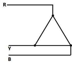
Sign in to UnlockThe phase sequence of the 3-phase system shown in Figure is
Explanation Locked!
Unlock this branch to view the explanation, track, bookmark and more.
Sign in to UnlockAn 800 kV transmission line is having per phase line inductance of 1.1mH/km and per phase line capacitance of 11.68nF/km. Ignoring the length of the line, its ideal power transfer capability in MW is
Explanation Locked!
Unlock this branch to view the explanation, track, bookmark and more.
Sign in to UnlockA 110 kV, single core coaxial, XLPE insulated power cable delivering power at 50 Hz, has a capacitance of 125nF/km. If the dielectric loss tangent of XLPE is , the dielectric power loss in this cable in W/km is

Explanation Locked!
Unlock this branch to view the explanation, track, bookmark and more.
Sign in to UnlockA lightning stroke discharges impulse current of 10 kA (peak) on a 400 kV transmission line having surge impedance of 250Ω. The magnitude of transient over-voltage traveling waves in either direction assuming equal distribution form the point of lightning strike will be
Explanation Locked!
Unlock this branch to view the explanation, track, bookmark and more.
Sign in to UnlockThe generalized circuit constants of a 3-phase, 220 kV rated voltage, medium length transmission line are


If the load at the receiving end is 50 MW at 220 kV with a power factor of 0.9 lagging, the magnitude of line to line sending end voltage should be
Explanation Locked!
Unlock this branch to view the explanation, track, bookmark and more.
Sign in to UnlockA new generator having [equivalent to (1.212+j0.70) p.u. and synchronous reactanceof 1.0 p.u. on the system base, is to be connected to a bus having voltage in the existing power system. This existing power system can be represented by Thevenin’s voltage in series with Thevenin’s impedance . The magnitude of the bus voltage of the system in pu will be


Explanation Locked!
Unlock this branch to view the explanation, track, bookmark and more.
Sign in to Unlock