
If , then S has the value


1
Explanation Locked!
Unlock this branch to view the explanation, track, bookmark and more.
Sign in to UnlockThe solution of the first order differential equation is:


Explanation Locked!
Unlock this branch to view the explanation, track, bookmark and more.
Sign in to UnlockIf u(t) is the unit step and δ(t) is the unit impulse function, the inverse z-transform of for k ≥ 0 is:


Explanation Locked!
Unlock this branch to view the explanation, track, bookmark and more.
Sign in to UnlockIf P and Q are two random events, then the following is TRUE:
Explanation Locked!
Unlock this branch to view the explanation, track, bookmark and more.
Sign in to UnlockFor the function, the maximum occurs when x is equal to:

Explanation Locked!
Unlock this branch to view the explanation, track, bookmark and more.
Sign in to UnlockA fair coin is tossed three times in succession. If the first toss produces a head, then the probability of getting exactly two heads in three tosses is:


Explanation Locked!
Unlock this branch to view the explanation, track, bookmark and more.
Sign in to UnlockFor the equation, the solution x(t) approaches the following values at t →∞

0

5
10
Explanation Locked!
Unlock this branch to view the explanation, track, bookmark and more.
Sign in to UnlockFor the scalar field , the magnitude of the gradient at the point (1,3) is:


Explanation Locked!
Unlock this branch to view the explanation, track, bookmark and more.
Sign in to UnlockFor the three-phase circuit shown in Figure, the ratio of the current is given by

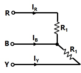


Explanation Locked!
Unlock this branch to view the explanation, track, bookmark and more.
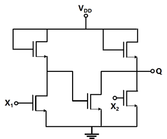
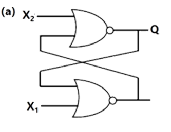
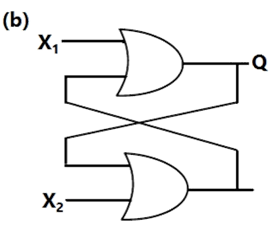
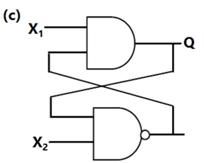
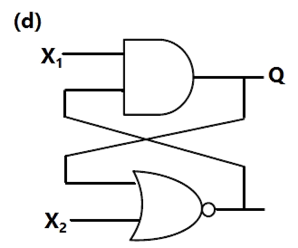
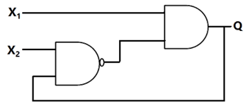
Sign in to UnlockIf X1 and X2 are the inputs to the circuit shown in figure, the output Q is:


Explanation Locked!
Unlock this branch to view the explanation, track, bookmark and more.
Sign in to UnlockThe Laplace transform of a function f(t) is . As t →∞, f(t) approaches

3
5


Explanation Locked!
Unlock this branch to view the explanation, track, bookmark and more.
Sign in to UnlockThe Q-meter works on the principle of
Explanation Locked!
Unlock this branch to view the explanation, track, bookmark and more.
Sign in to UnlockThe set-up in figure is used to measure resistance R. The ammeter and voltmeter resistances are 0.01Ω and 2000Ω, respectively. Their readings are 2A and 180V, respectively, giving a measured resistance of 90Ω. The percentage error in the measurement is:

Explanation Locked!
Unlock this branch to view the explanation, track, bookmark and more.
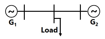
Sign in to UnlockA load centre is at an equidistant from the two thermal generating stations and as shown in Figure. The fuel cost characteristics of the generating stations are given by


Rs/hour

Rs/hour

Where and are the generation in MW of and , respectively. For most economic generation to meet 300 MW of load, and , respectively, are


Explanation Locked!
Unlock this branch to view the explanation, track, bookmark and more.
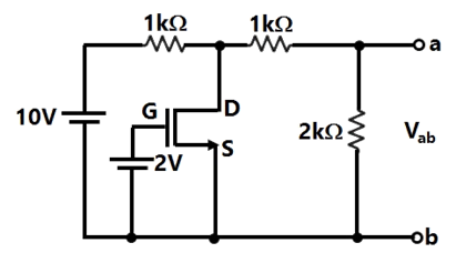
Sign in to UnlockAssume that the N-channel MOSFET shown in Figure is ideal, and that its threshold voltage is +1.0V. The voltage between nodes a and b is:

Explanation Locked!
Unlock this branch to view the explanation, track, bookmark and more.
Sign in to UnlockThe Fourier series for the function is:

Explanation Locked!
Unlock this branch to view the explanation, track, bookmark and more.
Sign in to UnlockThe typical frequency response of a two-stage direct coupled voltage amplifier is as shown in
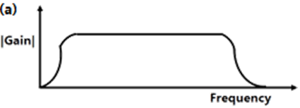
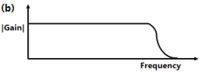
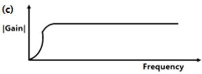

Explanation Locked!
Unlock this branch to view the explanation, track, bookmark and more.
Sign in to UnlockAn electric motor, developing a starting torque of 15 Nm, starts with a load torque of 7 Nm on its shaft. If the acceleration at start is , the moment of inertia of the systems must be (neglecting viscous and Coulomb/friction).


Explanation Locked!
Unlock this branch to view the explanation, track, bookmark and more.
Sign in to UnlockThe charge distribution in a metal-dielectric-semiconductor specimen is shown in Figure. The negative charge density decreases linearly in the semiconductor as shown. The electric field distribution is as shown in
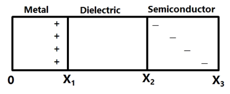

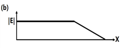
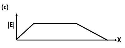
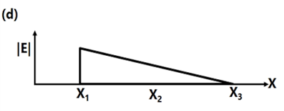
Explanation Locked!
Unlock this branch to view the explanation, track, bookmark and more.
Sign in to UnlockFor the triangular waveform shown in Figure, the RMS value of the voltage is equal to
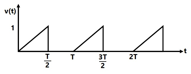


Explanation Locked!
Unlock this branch to view the explanation, track, bookmark and more.
Sign in to UnlockFor the two-port network shown in Figure, the Z-matrix is given by
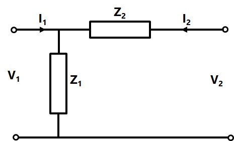


Explanation Locked!
Unlock this branch to view the explanation, track, bookmark and more.
Sign in to UnlockThe figure shows the root locus plot (location of poles not given) of a third-order system whose open-loop transfer function is


Explanation Locked!
Unlock this branch to view the explanation, track, bookmark and more.
Sign in to UnlockAssume that the threshold voltage of the N-channel MOSFET shown in Figure is +0.75V. The output characteristics of the MOSFET are also shown.
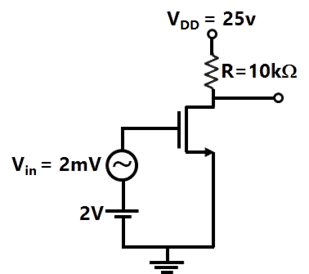
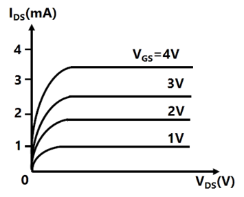
The transconductance of the MOSFET is:
Explanation Locked!
Unlock this branch to view the explanation, track, bookmark and more.
Sign in to UnlockAssume that the threshold voltage of the N-channel MOSFET shown in Figure is +0.75V. The output characteristics of the MOSFET are also shown.
The voltage gain of the amplifier is:
Explanation Locked!
Unlock this branch to view the explanation, track, bookmark and more.
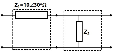
Sign in to UnlockTwo networks are connected in cascade as shown in Figure. With the usual notations the equivalent A, B, C and D constants are obtained. Given that
C = 0.025∠45°, the value of is:

Explanation Locked!
Unlock this branch to view the explanation, track, bookmark and more.
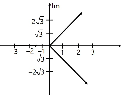
Sign in to UnlockThe simultaneous application of signals x(t) and y (t) to the horizontal and vertical plates, respectively, of an oscilloscope, produces a vertical figure-of - 8 display. If P and Q are constants, and x(t)=P sin(4t+30) , then y (t) is equal to
Explanation Locked!
Unlock this branch to view the explanation, track, bookmark and more.
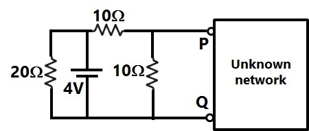
Sign in to UnlockIn Figure, the Thevenin’s equivalent pair (voltage, impedance), as seen at the terminals P-Q, is given by
Explanation Locked!
Unlock this branch to view the explanation, track, bookmark and more.
Sign in to UnlockThe output voltage waveform of a three-phase square-wave inverter contains
Explanation Locked!
Unlock this branch to view the explanation, track, bookmark and more.
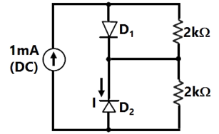
Sign in to UnlockAssume that and in Figure are ideal diodes. The value of current I is


Explanation Locked!
Unlock this branch to view the explanation, track, bookmark and more.
Sign in to UnlockThe digital circuit shown in figure works as a

Explanation Locked!
Unlock this branch to view the explanation, track, bookmark and more.
Sign in to UnlockThe network shown in Figure has impedances in p.u. as indicated. The diagonal element of the bus admittance matrix YBUS of the network is:


Explanation Locked!
Unlock this branch to view the explanation, track, bookmark and more.
Sign in to UnlockA unity feedback system, having an open loop gain , becomes stable when


Explanation Locked!
Unlock this branch to view the explanation, track, bookmark and more.
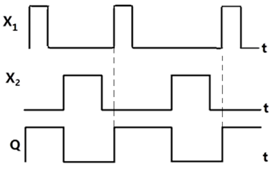
Sign in to UnlockSelect the circuit, which will produce the given output Q for the input signals X1 and X2 given in Figure.
Explanation Locked!
Unlock this branch to view the explanation, track, bookmark and more.
Sign in to UnlockA digital-to-analog converter with a full-scale output voltage of 3.5V has a resolution close to 14 mV. Its bit size is:
Explanation Locked!
Unlock this branch to view the explanation, track, bookmark and more.
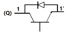
Sign in to UnlockIn figure, as long as and , the output Q remains


Explanation Locked!
Unlock this branch to view the explanation, track, bookmark and more.
Sign in to UnlockIn the matrix equation Px = q, which of the following is a necessary condition for the existence of at least one solution for the unknown vector x:
Explanation Locked!
Unlock this branch to view the explanation, track, bookmark and more.
Sign in to UnlockFor the matrix , one of the Eigen values is equal to –2. Which of the following is an Eigen vector?


Explanation Locked!
Unlock this branch to view the explanation, track, bookmark and more.
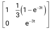
Sign in to UnlockA state variable system
, with the initial condition and the unit step input u(t) has


The state transition matrix


Explanation Locked!
Unlock this branch to view the explanation, track, bookmark and more.
Sign in to UnlockIf , the top row of is:


Explanation Locked!
Unlock this branch to view the explanation, track, bookmark and more.
Sign in to UnlockA state variable system
, with the initial condition and the unit step input u(t) has and the state transition equation


Explanation Locked!
Unlock this branch to view the explanation, track, bookmark and more.
Sign in to UnlockFigure shows a step-down chopper switched at 1 KHz with a duty ratio D = 0.5. The peak-peak ripple in the load current is close to

Explanation Locked!
Unlock this branch to view the explanation, track, bookmark and more.
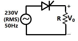
Sign in to UnlockConsider a phase controlled converter shown in Figure. The thyristor is fired at an angle α in every positive half cycle of the input voltage. If the peak value of the instantaneous output voltage equals 230 V, the firing angle α is close to
Explanation Locked!
Unlock this branch to view the explanation, track, bookmark and more.
Sign in to UnlockThe 8085 assembly language instruction that stores the contents of H and L registers into the memory locations 2050H and 2051H, respectively, is:
Explanation Locked!
Unlock this branch to view the explanation, track, bookmark and more.
Sign in to UnlockA generator with constant 1.0p.u. terminal voltage supplies power through a step-up transformer of 0.12p.u. reactance and a double-circuit line to an infinite bus bas as shown in Figure. The infinite bus voltage is maintained at 1.0p.u. Neglecting the resistances and susceptances of the system, the steady state stability power limit of the system is 6.25p.u. If one of the double-circuit is tripped, the resulting steady state stability power limit in p.u. will be
Explanation Locked!
Unlock this branch to view the explanation, track, bookmark and more.
Sign in to UnlockIn Figure, the initial capacitor voltage is zero. The switch is closed at t = 0. The final steady-state voltage across the capacitor is:
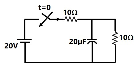
Explanation Locked!
Unlock this branch to view the explanation, track, bookmark and more.
Sign in to UnlockThe circuit shown in Figure is in steady state, when the switch is closed at t = 0. Assuming that the inductance is ideal, the current through the inductor at equals

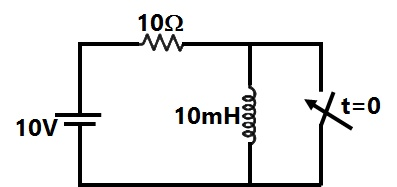
Explanation Locked!
Unlock this branch to view the explanation, track, bookmark and more.
Sign in to UnlockA system with zero initial conditions has the closed loop transfer function. The system output is zero at the frequency

Explanation Locked!
Unlock this branch to view the explanation, track, bookmark and more.
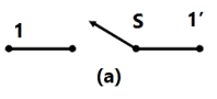
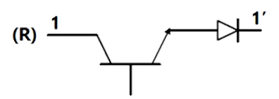
Sign in to UnlockA coil of inductance 10H resistance is connected as shown in figure. After the switch S has been in connected with point 1 for a very long time, it is moved to point 2 at t=0

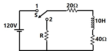
If, at t = 0+, the voltage across the coil is 120V, the value of resistance R is:
Explanation Locked!
Unlock this branch to view the explanation, track, bookmark and more.
Sign in to UnlockThe common emitter amplifier shown in Figure is biased using a 1mA ideal current source. The approximate base current value is:
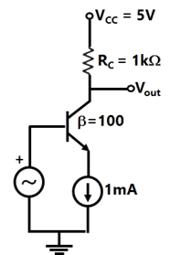
Explanation Locked!
Unlock this branch to view the explanation, track, bookmark and more.
Sign in to UnlockThe gain margin of a unity feedback control system with the open loop transfer function is:

0


Explanation Locked!
Unlock this branch to view the explanation, track, bookmark and more.
Sign in to UnlockA coil of inductance 10H resistance is connected as shown in figure. After the switch S has been in connected with point 1 for a very long time, it is moved to point 2 at t=0
For the value of R =40 ohm, the time taken for 95% of the stored energy dissipated is close to
Explanation Locked!
Unlock this branch to view the explanation, track, bookmark and more.
Sign in to UnlockThe conduction loss versus device current characteristic of a power MOSFET is best approximated by
Explanation Locked!
Unlock this branch to view the explanation, track, bookmark and more.
Sign in to UnlockIn the GH(s) plane, the Nyquist plot of the loop transfer function passes through the negative real axis at the point

Explanation Locked!
Unlock this branch to view the explanation, track, bookmark and more.
Sign in to UnlockFigure shows the voltage across a power semiconductor device and the current through the device during a switching transition. Is the transition a turn ON transition or a turn OFF transition? What is the energy lost during the transition?
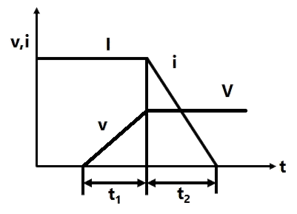
Turn ON,

Turn OFF,

Turn ON,
Turn OFF,
Explanation Locked!
Unlock this branch to view the explanation, track, bookmark and more.
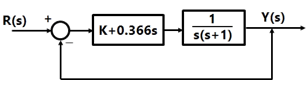
Sign in to UnlockIf the compensated system shown in Figure has a phase margin of 60° at the crossover frequency of 1rad/sec, the value of the gain K is:
Explanation Locked!
Unlock this branch to view the explanation, track, bookmark and more.
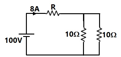
Sign in to UnlockFigure the value of R is
Explanation Locked!
Unlock this branch to view the explanation, track, bookmark and more.
Sign in to UnlockIf is the electric field intensity, is equal to


Null vector
Zero
Explanation Locked!
Unlock this branch to view the explanation, track, bookmark and more.
Sign in to UnlockAn electronic switch S is required to block voltages of either polarity during its OFF state as shown in Figure a. This switch is required to conduct in only one direction during its ON state as shown in Figure b.
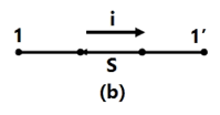
Which of the following are valid realizations of the switch S?


Explanation Locked!
Unlock this branch to view the explanation, track, bookmark and more.
Sign in to UnlockThe p.u. parameters for a 500 MVA machine on its own base are:
Inertia M = 20 p.u.; reactance X = 2 p.u.
The p.u. values of inertia and reactance on 100 MVA common base, respectively, are
Explanation Locked!
Unlock this branch to view the explanation, track, bookmark and more.
Sign in to UnlockThe parameters of a transposed overhead transmission line are given as:
Self reactance / km and Mutual reactance


The positive sequence reactance and zero sequence reactance, respectively, in Ω/km are


Explanation Locked!
Unlock this branch to view the explanation, track, bookmark and more.
Sign in to UnlockAt a 220 kV substation of a power system, it is given that the three-phase fault level is 4000 MVA and single-line to ground fault level is 5000 MVA. Neglecting the resistance and the shunt susceptances of the system,
(A) The positive sequence driving point reactance at the bus is:
(a) 2.5 Ω (b) 4.033 Ω
(c) 5.5 Ω (d) 12.1 Ω
(B) And the zero sequence driving point reactance at the bus is:
(a) 2.2 Ω (b) 4.84 Ω
(c) 18.18 Ω (d) 22.72 Ω
Explanation Locked!
Unlock this branch to view the explanation, track, bookmark and more.
Sign in to UnlockA three-phase diode bridge rectifier is fed from a 400V RMS, 50 Hz, three-phase AC source. If the load is purely resistive, the peak instantaneous output voltage is equal to
400 V
V

V

V

Explanation Locked!
Unlock this branch to view the explanation, track, bookmark and more.
Sign in to UnlockWhen subjected to a unit step input, the closed loop control system shown in Figure will have a steady state error of
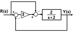
Explanation Locked!
Unlock this branch to view the explanation, track, bookmark and more.
Sign in to UnlockThe RMS value of the voltage is:


5V
7V

Explanation Locked!
Unlock this branch to view the explanation, track, bookmark and more.
Sign in to UnlockAt a 220 kV substation of a power system, it is given that the three-phase fault level is 4000 MVA and single-line to ground fault level is 5000 MVA. Neglecting the resistance and the shunt susceptances of the system, the zero sequence driving point reactance at the bus is:
Explanation Locked!
Unlock this branch to view the explanation, track, bookmark and more.
Sign in to UnlockThe RL circuit of Figure is fed from a constant magnitude, variable frequency sinusoidal voltage source . At 100 Hz, the R and L elements each have a voltage drop . If the frequency of the source is changed to 50 Hz, the new voltage drop across R is:


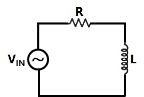


Explanation Locked!
Unlock this branch to view the explanation, track, bookmark and more.
Sign in to UnlockConsider the inverting amplifier, using an ideal operational amplifier shown in Figure. The designer wishes to realize the input resistance seen by the small signal source to be as large as possible, while keeping the voltage gain between –10 and –25, the upper limit on is 1 MΩ. The value of should be


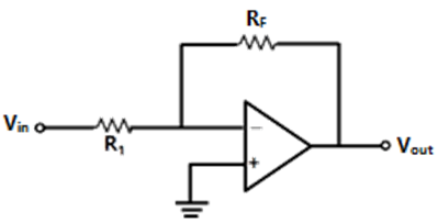
Infinity


Explanation Locked!
Unlock this branch to view the explanation, track, bookmark and more.
Sign in to UnlockIn relation to the synchronous machines, which one of the following statements is false?
Explanation Locked!
Unlock this branch to view the explanation, track, bookmark and more.
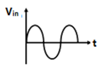
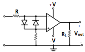
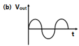
Sign in to UnlockIn Figure if the input is a sinusoidal signal, the output will appear as shown in


Explanation Locked!
Unlock this branch to view the explanation, track, bookmark and more.
Sign in to UnlockA 1000 kVA, 6.6 kV, 3-phase star connected cylindrical pole synchronous generator has a synchronous reactance of 20 Ω. Neglect the armature resistance and consider operation at full load and unity power factor.
The induced emf (line-to-line) is close to
Explanation Locked!
Unlock this branch to view the explanation, track, bookmark and more.
Sign in to UnlockA 1000 kVA, 6.6 kV, 3-phase star connected cylindrical pole synchronous generator has a synchronous reactance of 20 Ω. Neglect the armature resistance and consider operation at full load and unity power factor.
The power (or torque) angle is close to?
Explanation Locked!
Unlock this branch to view the explanation, track, bookmark and more.
Sign in to UnlockTwo magnetic poles revolve around a stationary armature carrying two coils as shown in Figure. Consider the instant when the poles are in a position as shown. Identify the correct statement regarding the polarity of the induced EMF at this instant in coil sides and


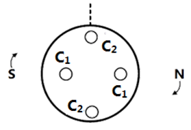


Explanation Locked!
Unlock this branch to view the explanation, track, bookmark and more.
Sign in to UnlockA 50 kW dc shunt motor is loaded to draw rated armature current at any given speed. When driven (i) at half the rated speed by armature voltage control and (ii) at 1.5 times the rated speed by field control, the respective output powers delivered by the motor are approximately
Explanation Locked!
Unlock this branch to view the explanation, track, bookmark and more.
Sign in to UnlockTwo wattmeters, which are connected to measure the total power on a three phase system supplying a balanced load, read 10.5 kW and -2.5 kW, respectively. The total power and the power factor, respectively, are
Explanation Locked!
Unlock this branch to view the explanation, track, bookmark and more.
Sign in to UnlockIn relation to DC machines, match the following and choose the correct combination.
Group –1 Performance Variables | Group – 2 Proportional to |
(P) Armature emf (E) (Q) Developed torque (T) (R) Developed power (P) | (1) Flux ( φ), speed (ω) and armature current () (2) φ and ω only (3) φ and only (4) and ω only (5) only |

Explanation Locked!
Unlock this branch to view the explanation, track, bookmark and more.
Sign in to UnlockOn the torque/speed curve of induction motor shown in Figure, four points of operation are market as W, X, Y and Z. Which one of them represents the operation at a slip greater than 1?
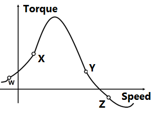
Explanation Locked!
Unlock this branch to view the explanation, track, bookmark and more.
Sign in to UnlockA PMMC voltmeter is connected across a series combination of a DC voltage source and an AC voltage source. The meter reads


2V
5V
V

V

Explanation Locked!
Unlock this branch to view the explanation, track, bookmark and more.
Sign in to UnlockFor an induction motor, operating at a slip s, the ratio of gross power output to air gap power is equal to:

(1 – s)


Explanation Locked!
Unlock this branch to view the explanation, track, bookmark and more.
Sign in to UnlockA DC ammeter has a resistance of 0.1Ω and its current range is 0 – 100A. If the range is to be extended to 0 – 500A, the meter requires the following shunt resistance
Explanation Locked!
Unlock this branch to view the explanation, track, bookmark and more.
Sign in to UnlockUnder no load condition, if the applied voltage to an induction motor is reduced from the rated voltage to half the rated value,
Explanation Locked!
Unlock this branch to view the explanation, track, bookmark and more.
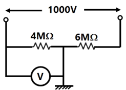
Sign in to UnlockA 1000 V DC supply has two 1-core cables as its positive and negative leads; their insulation resistances to earth are 4 MΩ and 6 MΩ, respectively, as shown in Figure. A voltmeter with resistance 50 KΩ is used to measure the insulation of the cable. When connected between the positive core and earth, the voltmeter reads
Explanation Locked!
Unlock this branch to view the explanation, track, bookmark and more.
Sign in to UnlockA three-phase cage induction motor is started by direct-on-line (DOL) switching at the rated voltage. If the starting current drawn is 6 times the full load current, and the full load slip is 4%, the ratio of the starting developed torque to the full load torque is approximately equal to
Explanation Locked!
Unlock this branch to view the explanation, track, bookmark and more.
Sign in to UnlockWhich three-phase connection can be used in a transformer to introduce a phase difference of 30° between its output and corresponding input line voltages
Explanation Locked!
Unlock this branch to view the explanation, track, bookmark and more.
Sign in to UnlockIn a single phase induction motor driving a fan load, the reason for having a high resistance rotor is to achieve
Explanation Locked!
Unlock this branch to view the explanation, track, bookmark and more.
Sign in to UnlockDetermine the correctness or otherwise of the following Assertion [a] and the Reason [r].
Assertion: Under V/f control of induction motor, the maximum value of the developed torque remains constant over a wide range of speed in the sub-synchronous region.
Reason: The magnetic flux is maintained almost constant at the rated value by keeping the ratio V/f constant over the considered speed range.
Explanation Locked!
Unlock this branch to view the explanation, track, bookmark and more.
Sign in to UnlockThe equivalent circuit of a transformer has leakage reactance and magnetizing reactance . Their magnitudes satisfy


Explanation Locked!
Unlock this branch to view the explanation, track, bookmark and more.
Sign in to UnlockAn 800 kV transmission line has a maximum power transfer capacity P, on the operated at 400 kV with the series reactance unchanged, the new maximum power transfer capacity is approximately
P
2P


Explanation Locked!
Unlock this branch to view the explanation, track, bookmark and more.
Sign in to UnlockThe insulation strength of an EHV transmission line is mainly governed by
Explanation Locked!
Unlock this branch to view the explanation, track, bookmark and more.
Sign in to UnlockHigh Voltage DC (HVDC) transmission is mainly used for
Explanation Locked!
Unlock this branch to view the explanation, track, bookmark and more.
Sign in to UnlockAt an industrial sub-station with a 4 MW load, a capacitor of 2 MVAR is installed to maintain the load power factor at 0.97 lagging. If the capacitor goes out of service, the load power factor becomes
Explanation Locked!
Unlock this branch to view the explanation, track, bookmark and more.
Sign in to Unlock