
For the differential equation with initial conditions and. The solution is


Explanation Locked!
Unlock this branch to view the explanation, track, bookmark and more.
Sign in to Unlockx(t) is a positive rectangular pulse from to with unit height as shown in the figure. The value of where is the Fourier transform of x(t) is


2

4

Explanation Locked!
Unlock this branch to view the explanation, track, bookmark and more.
Sign in to UnlockGiven f(t) and g(t) as shown below:
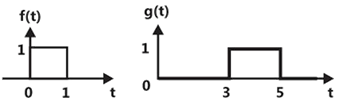
g(t) can be expressed as


Explanation Locked!
Unlock this branch to view the explanation, track, bookmark and more.
Sign in to UnlockA box contains 4 white balls and 3 red balls, In succession, two balls are randomly selected and removed from the box. Given that the first removed ball is white, the probability that the second removed ball is red is
Explanation Locked!
Unlock this branch to view the explanation, track, bookmark and more.
Sign in to UnlockGiven f(t) and g(t) as shown below:
The Laplace transform of g(t) is


Explanation Locked!
Unlock this branch to view the explanation, track, bookmark and more.
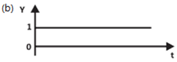
Sign in to UnlockThe TTL circuit shown in the figure is fed with the waveform X (also shown). All gates have equal propagation delay of 10ns. The output Y of the circuit is


Explanation Locked!
Unlock this branch to view the explanation, track, bookmark and more.
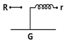
Sign in to UnlockThe Maxwell’s bridge shown in the figure is at balance. The parameters of the inductive coil are


Explanation Locked!
Unlock this branch to view the explanation, track, bookmark and more.
Sign in to UnlockThe characteristics equation of a closed-loop system is
. Which of the following statements is true?

Its root are always real
It cannot have a breakaway point in the range

Two of its roots land to infinity along the asymptotes

If may have complex roots in the right half plane.
Explanation Locked!
Unlock this branch to view the explanation, track, bookmark and more.
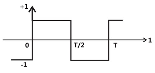
Sign in to UnlockThe second harmonic component of the periodic waveform given in the figure has amplitude of
0
1


Explanation Locked!
Unlock this branch to view the explanation, track, bookmark and more.
Sign in to UnlockThe system represented by the input-output relationship

Explanation Locked!
Unlock this branch to view the explanation, track, bookmark and more.
Sign in to UnlockThe period of the signal is


Explanation Locked!
Unlock this branch to view the explanation, track, bookmark and more.
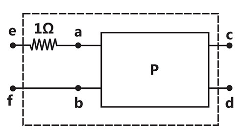
Sign in to UnlockThe two-port network P shown in the figure has ports 1 and 2. Denoted by terminals (a, b) and (c, d) respectively. It has an impedance matrix Z with parameters denoted by resistor is connected in series with the network at port 1 as shown in the figure. The impedance matrix of the modified two-port network (shown as a dashed box) is


Explanation Locked!
Unlock this branch to view the explanation, track, bookmark and more.
Sign in to UnlockThe value of the quantity P, where. Is equal to

Explanation Locked!
Unlock this branch to view the explanation, track, bookmark and more.
Sign in to UnlockGiven the finite length input x[n] and the corresponding finite length output y[n] of an LTI system as shown below, the impulse response h[n] of the system is
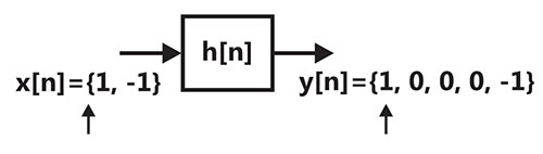


Explanation Locked!
Unlock this branch to view the explanation, track, bookmark and more.
Sign in to UnlockThe following Karnaugh map represents a function F.
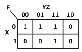
A minimized form of the function F is


Explanation Locked!
Unlock this branch to view the explanation, track, bookmark and more.
Sign in to UnlockDivergence of the three-dimensional radial vector field is

3
1/r


Explanation Locked!
Unlock this branch to view the explanation, track, bookmark and more.
Sign in to UnlockAt t = 0, the function has

Explanation Locked!
Unlock this branch to view the explanation, track, bookmark and more.
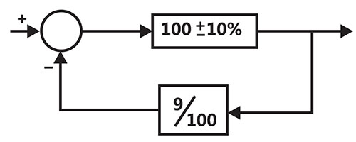
Sign in to UnlockAs shown in the figure, a negative feedback system has an amplifier of gain 100 with ±10% tolerance in the forward path, and an attenuator of value 9/100 in the feedback path. The overall system gain is approximately:
Explanation Locked!
Unlock this branch to view the explanation, track, bookmark and more.
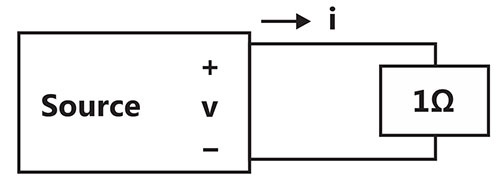
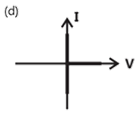
Sign in to UnlockAs shown in the figure, a resistance is connected across a source that has a load line

v + i = 100. The current through the resistance is
Explanation Locked!
Unlock this branch to view the explanation, track, bookmark and more.
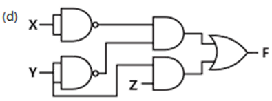
Sign in to UnlockThe following Karnaugh map represents a function F.
Which of the following circuits is a realization of the above function F?


Explanation Locked!
Unlock this branch to view the explanation, track, bookmark and more.
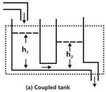
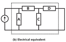
Sign in to UnlockIf the electrical circuit of figure (b) is an equivalent of the coupled tank system of figure (a). then
Explanation Locked!
Unlock this branch to view the explanation, track, bookmark and more.
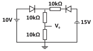
Sign in to UnlockAssuming that the diodes in the given circuit are ideal, the voltage is

Explanation Locked!
Unlock this branch to view the explanation, track, bookmark and more.
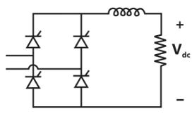
Sign in to UnlockThe power electronic converter shown in the figure has a single-pole double-throw switch. The pole P of the switch is connected alternately to throws A and B. The converter shown in figure is
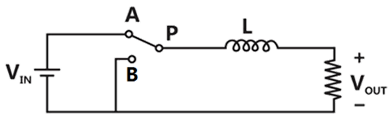
Explanation Locked!
Unlock this branch to view the explanation, track, bookmark and more.
Sign in to UnlockThe system with is


Explanation Locked!
Unlock this branch to view the explanation, track, bookmark and more.
Sign in to UnlockWhen a “CALL” Addr” instruction is executed. The CPU carries out the following sequential operations internally:
Note:
(R) means content of register R
((R)) means content of memory location pointed to by R
PC means program counter
SP means stack pointer


Explanation Locked!
Unlock this branch to view the explanation, track, bookmark and more.
Sign in to UnlockThe switch in the circuit has been closed for a long time. It is opened at t = 0. At , the current through the line capacitor is


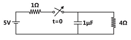
Explanation Locked!
Unlock this branch to view the explanation, track, bookmark and more.
Sign in to UnlockThe transistor circuit shown uses a silicon transistor with and a dc current gain of 100. The value of is


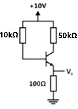
Explanation Locked!
Unlock this branch to view the explanation, track, bookmark and more.
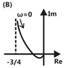
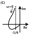
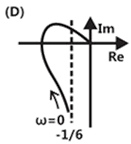
Sign in to UnlockThe frequency response of plotted in the complex plane is


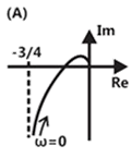
Explanation Locked!
Unlock this branch to view the explanation, track, bookmark and more.
Sign in to UnlockAn eigenvector of is


Explanation Locked!
Unlock this branch to view the explanation, track, bookmark and more.
Sign in to UnlockFor the set of equations


The following statement is true:
Only the trivial solution exists.

There are no solutions.
A unique non-trivial solution exists
Multiple non-trivial solutions exist
Explanation Locked!
Unlock this branch to view the explanation, track, bookmark and more.
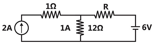
Sign in to UnlockIf the resistor draws a current of 1 A as shown in the figure, the value of resistance R is


Explanation Locked!
Unlock this branch to view the explanation, track, bookmark and more.
Sign in to UnlockA three-phase 33kV oil circuit breaker is rated 1200A, 2000MVA 3s. The symmetrical breaking current is
Explanation Locked!
Unlock this branch to view the explanation, track, bookmark and more.
Sign in to UnlockFigure shows a composite switch consisting of a power transistor (BJT) in series with a diode. Assuming that the transistor switch and the diode are ideal, the I-V characteristics of the composite switch is
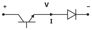
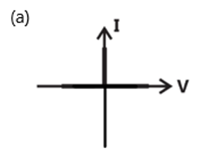
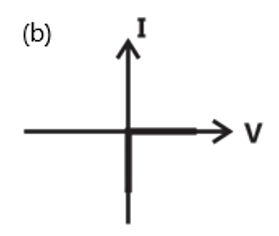
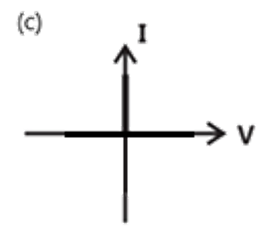
Explanation Locked!
Unlock this branch to view the explanation, track, bookmark and more.
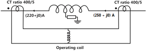
Sign in to UnlockConsider a stator winding of an alternator with an internal high-resistance ground fault. The current under the fault condition are as shown in the figure. The winding is protected using a differential current scheme with current transformers of ratio 400/5 A as shown. The current through the operating coil is
Explanation Locked!
Unlock this branch to view the explanation, track, bookmark and more.
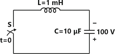
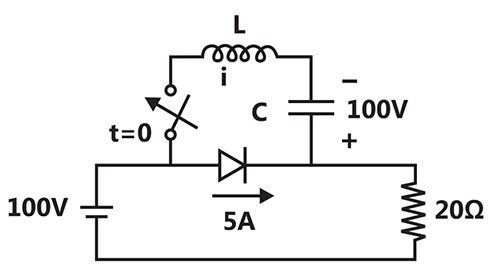
Sign in to UnlockThe L-C circuit shown in the figure has an impedance L = I mH and a capacitance C = 10uF.
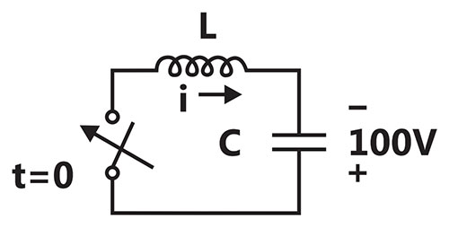
The initial current through the inductor is zero, while the initial capacitor voltage is 100V. The switch is closed at t = 0. The current i through the circuit is:


Explanation Locked!
Unlock this branch to view the explanation, track, bookmark and more.
Sign in to UnlockThe L-C circuit shown in the figure has an impedance L = I mH and a capacitance C = 10uF.
The LC circuit shown in the figure has an inductance and capacitance . The LC circuit is used to commutate a thyristor, which is initially carrying a current of 5A as shown in the figure below. The values and initial of and are same as in previous question. The switch is closed ae . If the forward drop is negligible, the time taken for the device to turn off is


Explanation Locked!
Unlock this branch to view the explanation, track, bookmark and more.
Sign in to UnlockFor the system , the approximate time taken for a step response to reach 98% of its final value is

Explanation Locked!
Unlock this branch to view the explanation, track, bookmark and more.
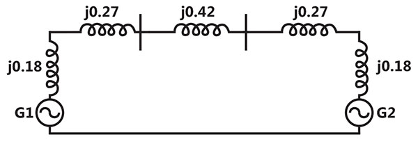
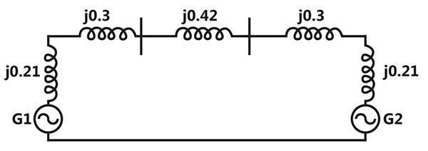
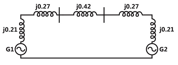
Sign in to UnlockFor the power system shown in the figure below. The specifications of the components are the following: [2010: 2 Marks]


Choose 25kV as the base voltage at the generator G1 and 200 MVA as the MVA base. The impedance diagram is

Explanation Locked!
Unlock this branch to view the explanation, track, bookmark and more.
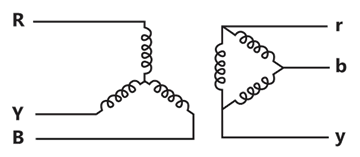
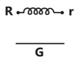
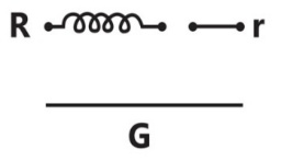
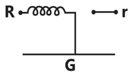
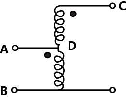
Sign in to UnlockThe zero-sequence circuit of the three phase transformers shown in the figure is
Explanation Locked!
Unlock this branch to view the explanation, track, bookmark and more.
Sign in to UnlockThe fully controlled thyristor converter in the figure is fed from a single-phase source. When the firing angle is, the dc output voltage of the converter is 300V. What will be the output voltage for a firing angle of , assuming continuous conduction?


150V
210V
300V

Explanation Locked!
Unlock this branch to view the explanation, track, bookmark and more.
Sign in to UnlockA separately excited DC motor runs at 1500 rpm under no-load with 200 V applied to the armature. The field voltage is maintained at its rated value. The speed of the motor when its delivers a torque of 5Nm is 1400rpm as shown in the figure. The rotational losses and armature reaction are neglected.
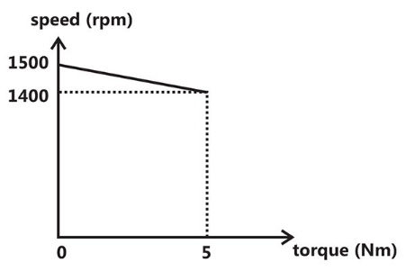
The armature resistance of the motor is.


Explanation Locked!
Unlock this branch to view the explanation, track, bookmark and more.
Sign in to UnlockA wattmeter is connected as shown in the figure. The wattmeter reads
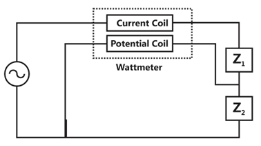
Zero always
Total power consumed by and


Power consumed by
Power consumed by
Explanation Locked!
Unlock this branch to view the explanation, track, bookmark and more.
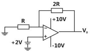
Sign in to UnlockGiven that the op-amp is ideal, the output voltage is

Explanation Locked!
Unlock this branch to view the explanation, track, bookmark and more.
Sign in to UnlockA separately excited DC motor runs at 1500 rpm under no-load with 200 V applied to the armature. The field voltage is maintained at its rated value. The speed of the motor when its delivers a torque of 5Nm is 1400rpm as shown in the figure. The rotational losses and armature reaction are neglected.
For the motor to deliver a torque of 2.5Nm at 1400 rpm. The armature voltage to be applied is
Explanation Locked!
Unlock this branch to view the explanation, track, bookmark and more.
Sign in to UnlockAn ammeter has a current range of 0 – 5 A, and this internal resistance is. In order to change the range to 0 – 25 A, we need to add a resistance of

in series with the meter

in series with the meter

in parallel with the meter

in parallel with the meter

Explanation Locked!
Unlock this branch to view the explanation, track, bookmark and more.
Sign in to UnlockA balanced three-phase voltage is applied to a star-connected induction motor, the phase to neutral voltage being V. The stator resistance, rotor resistance referred to the stator. Stator leakage reactance, rotor leakage reactance referred to the stator and the magnetizing reactance are denoted by and respectively. The magnitude of the starting current of the motor is given by:


Explanation Locked!
Unlock this branch to view the explanation, track, bookmark and more.
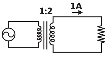
Sign in to UnlockA single-phase transformer has a turns ratio of 1:2 and is connected to a purely resistive load as shown in the figure. The magnetizing current drawn is 1 A, and the secondary current is 1 A. If core losses and leakage reactance are neglected, the primary current is
Explanation Locked!
Unlock this branch to view the explanation, track, bookmark and more.
Sign in to UnlockA separately excited dc machine is coupled to a 50Hz, three-phase. 4-pole induction machine as shown in the figure. The dc machine is energized first and the machines rotate at 1600rpm. Subsequently the induction machine is also connected to a 50Hz, three-phase source, the phase sequence being consistent with the direction of rotation, in steady state.

Explanation Locked!
Unlock this branch to view the explanation, track, bookmark and more.
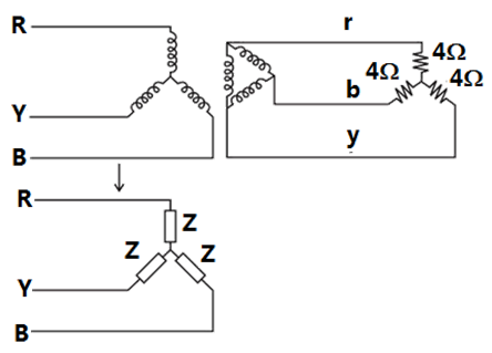
Sign in to UnlockA balanced star-connected and purely resistive load is connected at the secondary of a star-delta transformer as shown in the figure. The line-to-line voltage rating of the transformer is 110V/220V. Neglecting the non-idealities of the transformer, the impedance ‘Z’ of the equivalent star-connected load, referred to the primary side of the transformer, is:


Explanation Locked!
Unlock this branch to view the explanation, track, bookmark and more.
Sign in to UnlockPower is transferred from system A to system B by an HVDC link as shown in the figure. If the voltages and are as indicated in the figure and l > 0, then


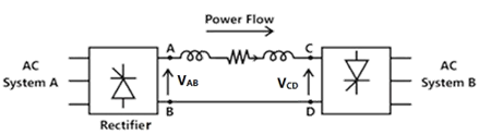


Explanation Locked!
Unlock this branch to view the explanation, track, bookmark and more.
Sign in to UnlockConsider a step voltage wave of magnitude 1pu travelling along a lossless transmission line that terminates in a reactor. The voltage magnitude across the reactor at the instant the travelling wave reaches the reactor is
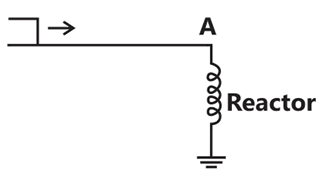
Explanation Locked!
Unlock this branch to view the explanation, track, bookmark and more.
Sign in to UnlockConsider two buses connected by an impedance of. The bus 1 voltage is 10030°V, and bus 2 voltage is . The real and reactive power supplied by bus 1, respectively are


Explanation Locked!
Unlock this branch to view the explanation, track, bookmark and more.
Sign in to UnlockA 50Hz synchronous generator is initially connected to a long lossless transmission line which is open circuited at the receiving end. With the field voltage held constant, the generator is disconnected from the transmission line. Which of the following may be said about the steady state terminal voltage and field current of the generator?

Explanation Locked!
Unlock this branch to view the explanation, track, bookmark and more.
Sign in to UnlockConsider a three-phase, 50Hz, 11kV distribution system. Each of the conductors is suspended by an insulator string having two identical porcelain insulators. The self capacitance of the insulator is 5 times, the shunt capacitance between the link and the ground, as shown in the figure. The voltages across the two insulators are
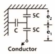


Explanation Locked!
Unlock this branch to view the explanation, track, bookmark and more.
Sign in to UnlockConsider a three-core, three-phase, 50Hz, 11kV cable whose conductors are denoted as R,Y, and B in the figure. The inter-phase capacitance () between each pair of conductors is and the capacitance between each line conductor and the sheath is. The per-phase charging current is


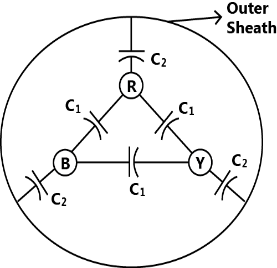
Explanation Locked!
Unlock this branch to view the explanation, track, bookmark and more.
Sign in to Unlock