
For the signal , the minimum sampling frequency (in Hz) satisfying the Nyquist criterion is _________.

Explanation Locked!
Unlock this branch to view the explanation, track, bookmark and more.
Sign in to UnlockA sinusoid x(t) of unknown frequency is sampled by an impulse train of period 20ms. The resulting sample train is next applied to an ideal low pass filter with a cutoff at 25Hz. The filter output is seen to be a sinusoid of frequency 20Hz. This means that x(t) has a frequency of
Explanation Locked!
Unlock this branch to view the explanation, track, bookmark and more.
Sign in to UnlockThe line A to neutral voltage is for a balanced three phase star-connected load with phase sequence ABC. The voltage of line B with respect to line C is given by


Explanation Locked!
Unlock this branch to view the explanation, track, bookmark and more.
Sign in to UnlockIntegration of the complex function, in the counterclockwise direction, around, is


0


Explanation Locked!
Unlock this branch to view the explanation, track, bookmark and more.
Sign in to UnlockA hysteresis type TTL inverter is used to realize an oscillator in the circuit shown in the figure.
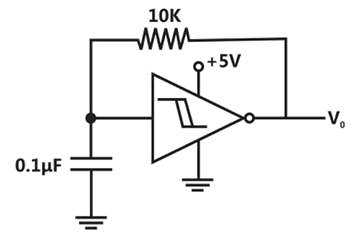
If the lower and upper trigger level voltages are 0.9V and 1.7V, the period (in ms), for which output is LOW, is ______________.
Explanation Locked!
Unlock this branch to view the explanation, track, bookmark and more.
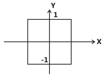
Sign in to UnlockA function f(t) is shown in the figure.
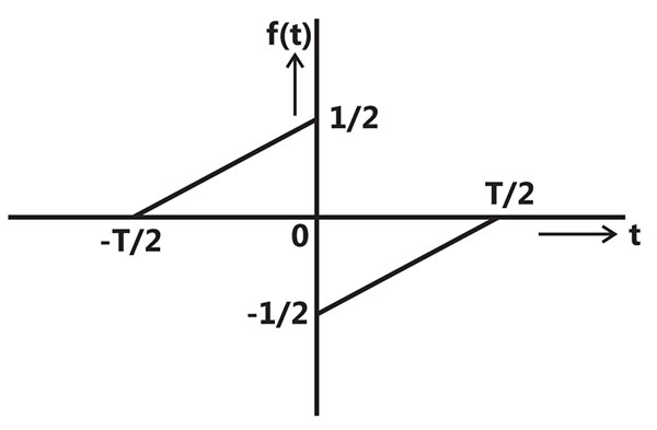
The Fourier transform of f(t) is

Real and even function of

Real and odd function of
Imaginary and odd function of
Imaginary and even function of
Explanation Locked!
Unlock this branch to view the explanation, track, bookmark and more.
Sign in to UnlockThe mean thickness and variance of silicon steel laminations are 0.2mm and 0.02 respectively. The varnish insulation is applied on both the sides of the laminations. The mean thickness of one side insulation and its variance are 0.1mm and 0.01 respectively. If the transformer core is made using 100 such varnish coated laminations, the mean thickness and variance of the core respectively are
Explanation Locked!
Unlock this branch to view the explanation, track, bookmark and more.
Sign in to UnlockA signal is represented by

The Fourier transform of the convolved signal is


Explanation Locked!
Unlock this branch to view the explanation, track, bookmark and more.
Sign in to UnlockThe function is to be solved using Newton-Raphson method. If the initial value of is taken as 1.0, then the absolute error observed at iteration is ________.


Explanation Locked!
Unlock this branch to view the explanation, track, bookmark and more.
Sign in to UnlockA continuous-time LTI system with system function has the following pole-zero plot. For this system, which of the alternatives is TRUE?

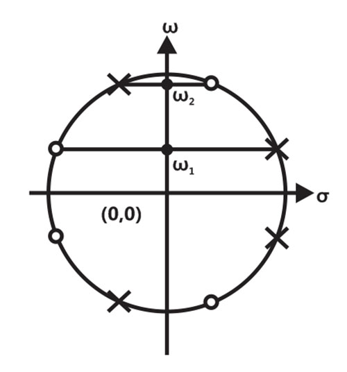

has multiple maxima, at and


= constant;

Explanation Locked!
Unlock this branch to view the explanation, track, bookmark and more.
Sign in to UnlockA differentiable non constant even function x(t) has a derivative y(t), and their respective Fourier Transformers are . Which of the following statements is TRUE?

are both real.
is real and is imaginary.


are both imaginary
is imaginary and is real.
Explanation Locked!
Unlock this branch to view the explanation, track, bookmark and more.
Sign in to UnlockLifetime of an electric bulb is a random variable with density, where x is measured in years. If the minimum and maximum lifetimes of bulb are 1 and 2 years respectively, then the value of k is ___________.

Explanation Locked!
Unlock this branch to view the explanation, track, bookmark and more.
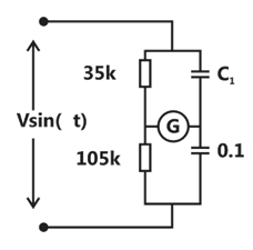
Sign in to UnlockIn the bridge circuit shown, the capacitors are loss free. At balance the value of capacitance in microfarad is _________________.

Explanation Locked!
Unlock this branch to view the explanation, track, bookmark and more.
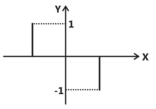
Sign in to UnlockThe two signals S1 and S2, shown in figure, are applied to Y and X deflection plates of an oscilloscope.
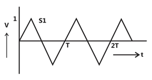
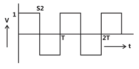
The waveform displayed on the screen is
Explanation Locked!
Unlock this branch to view the explanation, track, bookmark and more.
Sign in to UnlockThe signal flow graph of a system is shown below. U(s) is the input and C(s) is the output.
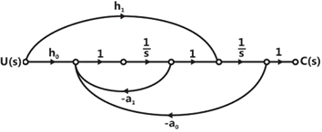
Assuming, , the input-output transfer function, of the system is given by


Explanation Locked!
Unlock this branch to view the explanation, track, bookmark and more.
Sign in to UnlockA state diagram of a logic gate which exhibits a delay in the output is shown in the figure, where X is the don’t care condition, and Q is the output representing the state.
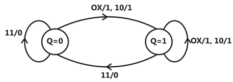
The logic gate represented by the gate diagram is
Explanation Locked!
Unlock this branch to view the explanation, track, bookmark and more.
Sign in to UnlockThe block diagram of a system is shown in the figure
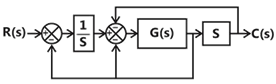
If the desired transfer function of the system is

Then G(s) is

s
1/s
This cannot be expressed in the required form for any value of G(s)
Explanation Locked!
Unlock this branch to view the explanation, track, bookmark and more.
Sign in to UnlockA non-ideal voltage source has an internal impedance of . If a purely resistive load is to be chosen that maximizes the power transferred to the load, its value must be


0
real part of
magnitude of
complex conjugate of
Explanation Locked!
Unlock this branch to view the explanation, track, bookmark and more.
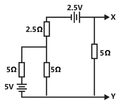
Sign in to UnlockThe Norton’s equivalent source in amperes as seen into the terminals X and Y is__________.
Explanation Locked!
Unlock this branch to view the explanation, track, bookmark and more.
Sign in to UnlockA 183-bus power system has 150 PQ buses and 32 PV buses. In the general case, to obtain the load flow solution using Newton-Raphson method in polar coordinates, the minimum number of simultaneous equations to be solved is
Explanation Locked!
Unlock this branch to view the explanation, track, bookmark and more.
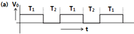
Sign in to UnlockTwo monoshot multivibrators, one positive edge triggered and another negative edge triggered are connected as shown in figure


The monoshots and when triggered produce pulse of width and respectively. Where . The steady state output voltage of the circuit is


Explanation Locked!
Unlock this branch to view the explanation, track, bookmark and more.
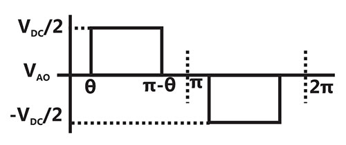
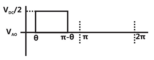
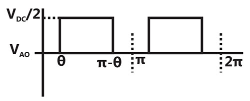
Sign in to UnlockA single-phase voltage source inverter shown in figure feeding power to a load. The triggering pulses of the devices are also shown in the figure.
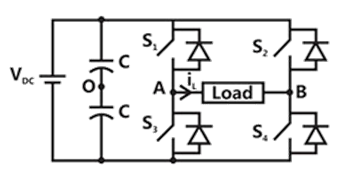
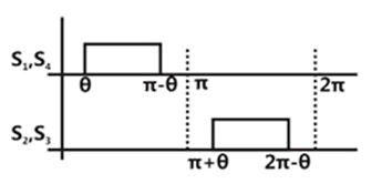
If the load current is sinusoidal and is zero at the node voltage has the waveform


Explanation Locked!
Unlock this branch to view the explanation, track, bookmark and more.
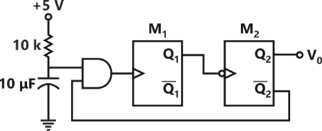
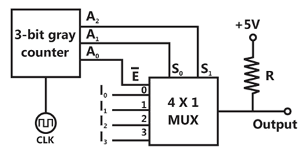
Sign in to UnlockA 3-bit gray counter is used to control the output of the multiplexer as shown in the figure. The initial state of the counter is . The output is pulled high. The output of the circuit follows the sequence


Explanation Locked!
Unlock this branch to view the explanation, track, bookmark and more.
Sign in to UnlockThe figure shows the single line diagram of the single machine infinite bus system.

The inertia constant of the synchronous generator . Frequency is 50Hz. Mechanical power is 1pu. The system is operating at the stable equilibrium point with rotor angle equal to . A three phase short circuit fault occurs at a certain location on one of the circuits of the double circuit transmission line. During fault, electrical power in pu is . If the values of and at the instant of fault clearing are and 3.762 radian/s respectively, then (in pu) is _________.


Explanation Locked!
Unlock this branch to view the explanation, track, bookmark and more.
Sign in to UnlockA particle, starting from origin at t = 0s, is travelling along x-axis with velocity

At t = 3s, the difference between the distance covered by the particle and the magnitude of displacement from the origin is ___________.
Explanation Locked!
Unlock this branch to view the explanation, track, bookmark and more.
Sign in to UnlockLet , where f and v are scalar and vector fields respectively. If , then is


2xy + 2yz + 2zx
x + y + z
0
Explanation Locked!
Unlock this branch to view the explanation, track, bookmark and more.
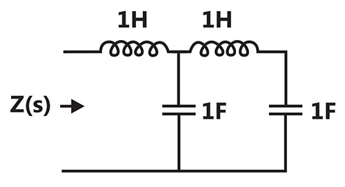
Sign in to UnlockThe driving point impedance Z(s) for the circuit shown below is


Explanation Locked!
Unlock this branch to view the explanation, track, bookmark and more.
Sign in to UnlockConsider the system described by following state space equations


If u is unit step input, then the steady error of the system is
Explanation Locked!
Unlock this branch to view the explanation, track, bookmark and more.
Sign in to UnlockIn 8085A microprocessor, the operation performed by the instruction LHLD is


Explanation Locked!
Unlock this branch to view the explanation, track, bookmark and more.
Sign in to UnlockA hollow metallic sphere of radius r is kept at potential of 1 Volt. The total electric flux coming out of the concentric spherical surface of radius R (> r) is


Explanation Locked!
Unlock this branch to view the explanation, track, bookmark and more.
Sign in to UnlockA single-input single-output feedback system has forward transfer function G(s) and feedback transfer function(s). It is given that. Which of the following is true about the stability of the system?

Explanation Locked!
Unlock this branch to view the explanation, track, bookmark and more.
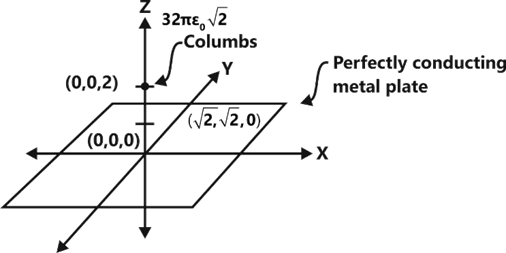
Sign in to UnlockA perfectly conducting metal plate is placed in x-y plane in a right-handed coordinate system. A charge of coulombs is placed at coordinate (0, 0, 2). is the permittivity of free space. Assume to be unit vectors along x, y and z axes, respectively. At the coordinate, the electric field vector (Newtons/Columbs) will be


Explanation Locked!
Unlock this branch to view the explanation, track, bookmark and more.
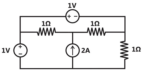
Sign in to UnlockThe power delivered by the current source, in the figure is_________.
Explanation Locked!
Unlock this branch to view the explanation, track, bookmark and more.
Sign in to UnlockThe magnitude Bode plot of a network s shown in the figure
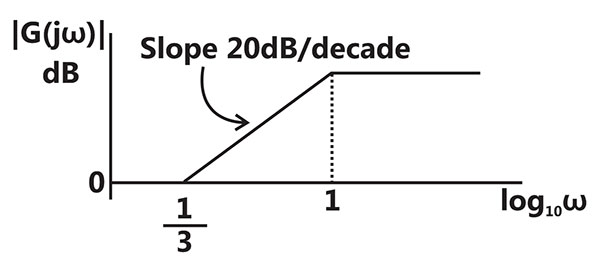
The maximum phase angle and the corresponding gain respectively, are


and 1.73dB

and 4.77dB
and 4.77dB

and 1.73dB
Explanation Locked!
Unlock this branch to view the explanation, track, bookmark and more.
Sign in to UnlockTwo matrices A and B are given below:

If the rank of matrix A is N, then the rank of matrix B is
Explanation Locked!
Unlock this branch to view the explanation, track, bookmark and more.
Sign in to UnlockFor a fully transposed transmission line
Explanation Locked!
Unlock this branch to view the explanation, track, bookmark and more.
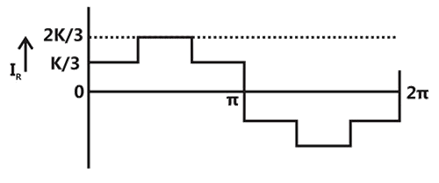
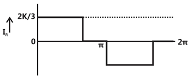
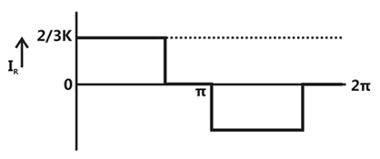
Sign in to UnlockA three-phase fully controlled bridge converter is fed through star-delta transformer as shown in the figure.
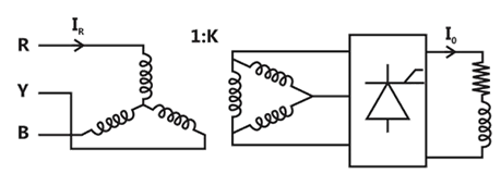
The converter is operated at a firing angle of , Assuming the load current to be virtually constant at 1p.u. and transformer to be an ideal one, the input phase current waveform is


Explanation Locked!
Unlock this branch to view the explanation, track, bookmark and more.
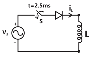
Sign in to UnlockA diode circuit feeds an ideal inductor as shows in the figure, Given , where , and L = 31.83 mH. The initial value of inductor current is zero. Switch S is closed at t = 2.5ms. The peak value of inductor current (in (a) in the first cycle is ____________.


Explanation Locked!
Unlock this branch to view the explanation, track, bookmark and more.
Sign in to UnlockA series RLC circuit is observed at two frequencies. At , we note that source voltage results in a current . At , the source voltage results in a current . The closest values for R, L, C out of the following options are


Explanation Locked!
Unlock this branch to view the explanation, track, bookmark and more.
Sign in to UnlockThe no-load speed of a 230 V separately excited dc motor is 1400rpm. The armature resistance drop and the brush drop are neglected. The field current is kept constant at rated value. The torque of the motor in Nm for an armature current of 8 A is ________.
Explanation Locked!
Unlock this branch to view the explanation, track, bookmark and more.
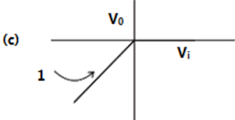
Sign in to UnlockAn operational-amplifier circuit is shown in the figure
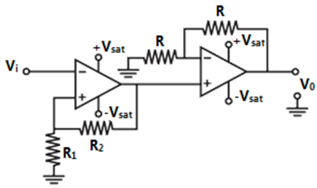
The output of the circuit for a given input is


Explanation Locked!
Unlock this branch to view the explanation, track, bookmark and more.
Sign in to UnlockA separately excited 300V DC shunt motor under no load runs at 900 rpm drawing an armature current of 2A. The armature resistance is and leakage inductance is 0.01H. When loaded, the armature current is 15A. Then the speed in rpm is __________.

Explanation Locked!
Unlock this branch to view the explanation, track, bookmark and more.
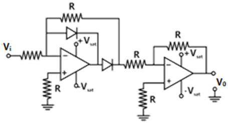
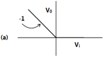
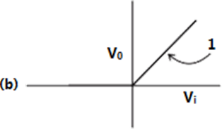
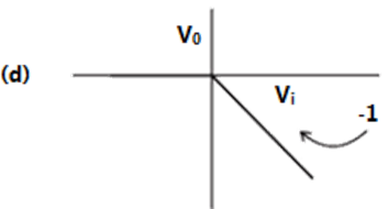
Sign in to UnlockThe transfer characteristic of the op-amp circuit shown in figure is
Explanation Locked!
Unlock this branch to view the explanation, track, bookmark and more.
Sign in to UnlockIn a synchronous machine, hunting is predominantly damped by
Explanation Locked!
Unlock this branch to view the explanation, track, bookmark and more.
Sign in to UnlockA non-salient pole synchronous generator having synchronous reactance of 0.8 pu is supplying 1 pu power to a unity power factor load at a terminal voltage of 1.1 pu. Neglecting the armature resistance, the angle of the voltage behind the synchronous reactance with respect to the angle of the terminal voltage in degrees is ______________.
Explanation Locked!
Unlock this branch to view the explanation, track, bookmark and more.
Sign in to UnlockAn LPF wattmeter of power factor 0.2 is having three voltage settings 300V, 150V and 75V, and two current settings 5A and 10A. The full scale reading is 150. If the wattmeter is used with 150V voltage setting and 10A current setting, the multiplying factor of the wattmeter is______________.
Explanation Locked!
Unlock this branch to view the explanation, track, bookmark and more.
Sign in to UnlockA periodic waveform observed across a load is represented by

The measured value, using moving iron voltmeter connected across the load, is


Explanation Locked!
Unlock this branch to view the explanation, track, bookmark and more.
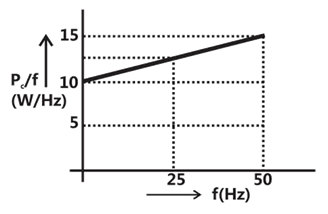
Sign in to UnlockAn open circuit test is performed on 50Hz transformer, using variable frequency source and keeping V/f ratio constant, to separate its eddy current and hysteresis losses. The variation of core loss/frequency as function of frequency is shown in the figure The hysteresis and eddy current losses of the transformer at 25Hz respectively are
Explanation Locked!
Unlock this branch to view the explanation, track, bookmark and more.
Sign in to UnlockThe load shown in the figure absorbs 4kW at a power factor of 0.89 lagging.
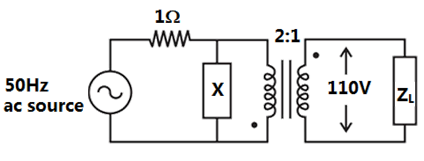
Assuming the transformer to be ideal, the value of the reactance X to improve the input power factor to unity is ________________.
Explanation Locked!
Unlock this branch to view the explanation, track, bookmark and more.
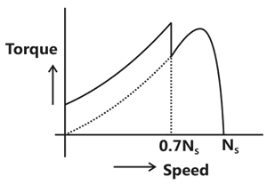
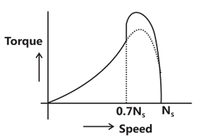
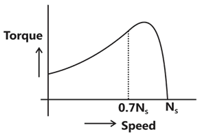
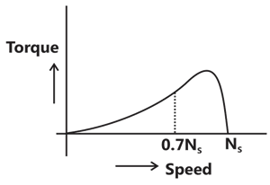
Sign in to UnlockA single phase induction motor is provided with capacitor and centrifugal switch in series with auxiliary winding. The switch is expected to operate at a speed of 0.7Ns, but due to malfunctioning the switch fails to operate. The torque-speed characteristics of the motor is represented by
Explanation Locked!
Unlock this branch to view the explanation, track, bookmark and more.
Sign in to UnlockThe parameters measured for a 220V/110V, 50Hz, single-phase transformer are:
Self inductance of primary winding = 45mH
Self inductance of secondary winding = 30mH
Mutual inductance between primary and secondary windings = 20mH
using the above parameters, the leakage and magnetizing inductance as referred to primary side in the equivalent circuit respectively, are


Explanation Locked!
Unlock this branch to view the explanation, track, bookmark and more.
Sign in to UnlockThe torque-speed characteristics of motor and load for two cases are shown in the figures ((a) and ((b). The load torque is equal to motor torque at points P, Q, R and S


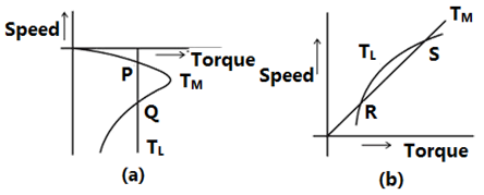
The stable operating points are
Explanation Locked!
Unlock this branch to view the explanation, track, bookmark and more.
Sign in to UnlockIn a long transmission line with r, l, g and c are the resistance, inductance, shunt conductance and capacitance per unit length, respectively, the condition for distortion less transmission is
rc = lg

rg = lc

Explanation Locked!
Unlock this branch to view the explanation, track, bookmark and more.
Sign in to UnlockFor a 400 km long transmission line, the series impedance is and the shunt admittance is μmho/km. The magnitude of the series impedance of the equivalent circuit of the transmission line is ____________.


Explanation Locked!
Unlock this branch to view the explanation, track, bookmark and more.
Sign in to UnlockThe complex power consumed by a constant-voltage load is given by , where and .A compensating shunt capacitor is chosen such that , where Q is the net reactive power consumed by the capacitor-load combination. The reactive power (in kVAR) supplied by the capacitor is ____________.


Explanation Locked!
Unlock this branch to view the explanation, track, bookmark and more.
Sign in to Unlock