
Match the following measuring equipment with their specific application:
(A) Kelvin double bridge (P) Capacitance
(B) Wind bridge (Q) Self-inductance
(C) Schering bridge (R) Frequency
(D) Maxwell’s bridge (S) Low resistance
Explanation Locked!
Unlock this branch to view the explanation, track, bookmark and more.
Sign in to UnlockIn a poly-phase squirrel-cage induction motor, increased starting torque can be obtained by
Explanation Locked!
Unlock this branch to view the explanation, track, bookmark and more.
Sign in to UnlockWhen a fixed amount of power is to be transmitted, the efficiency of transmission increases when
Explanation Locked!
Unlock this branch to view the explanation, track, bookmark and more.
Sign in to UnlockA fault occurring at the terminals at the terminals of an unloaded synchronous generator operating at its rated voltage has resulted in the following values of current and voltage


The fault that has occurred is _________________.
Explanation Locked!
Unlock this branch to view the explanation, track, bookmark and more.
Sign in to UnlockA generator is supplying 1 per unit power to an infinite bus through the system shown in figure. Following fault at F, circuit breakers and open simultaneously. The relationships in per unit are given by


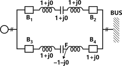
Pre-fault condition:

During fault condition:
When remain closed:


After open:

Calculate the critical angel before which breakers

and must open so that synchronism is not lost.
Explanation Locked!
Unlock this branch to view the explanation, track, bookmark and more.
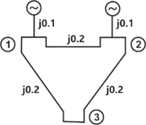
Sign in to UnlockA sample power system network is shown in figure. The reactance’s marked are in p.u. The p.u value of of the Bus Admittance Matrix is:


Explanation Locked!
Unlock this branch to view the explanation, track, bookmark and more.
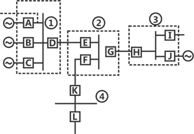
Sign in to UnlockIn a 4 bus system the circuit breakers and the various zones of protection are shown in figure. If the circuit breakers E, F and G trip, the location of the fault is on ___________
Explanation Locked!
Unlock this branch to view the explanation, track, bookmark and more.
Sign in to UnlockThe operating state that distinguishes a silicon controlled rectifier (SCR) from a diode is
Explanation Locked!
Unlock this branch to view the explanation, track, bookmark and more.
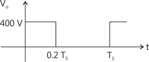
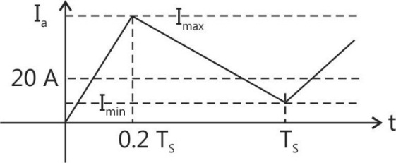
Sign in to UnlockFigure shows the circuit schematic of a chopper driven, separately excited d.c. motor. The single-pole double-throw switch operates with a switching period is 0.2. The motor may be assumed lossless, with an armature inductance of 10 mH. The motor draws an average current of 20A at a constant back emf of 80V, under steady state.

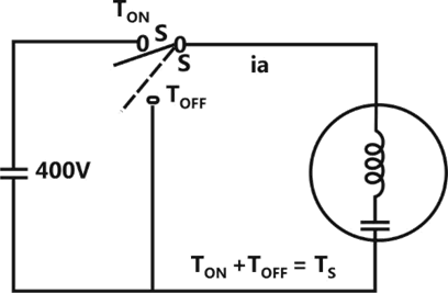
(a) Sketch and label the voltage waveform of the chopper for one switching period

(b) Sketch and label the motor current for one switching period.

(c) Evaluate the peak-to-peak current ripple of the motor.


Explanation Locked!
Unlock this branch to view the explanation, track, bookmark and more.
Sign in to UnlockTwo identical watt-meters are connected to measure power in a 3-phase 3-wire balanced load. What is the load power factor if
(a)

(b) Either is zero ____________

Explanation Locked!
Unlock this branch to view the explanation, track, bookmark and more.
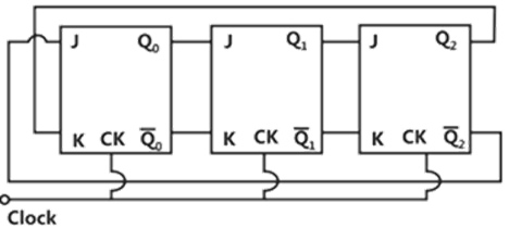
Sign in to UnlockThe three stage Johnson ring counter shown in figure is clock at a constant frequency of from the starting stage of . The frequency of outputs will be


Explanation Locked!
Unlock this branch to view the explanation, track, bookmark and more.
Sign in to UnlockThe ratio and phase angle errors in a well designed current transformer (CT) are kept within specified limits by using
Explanation Locked!
Unlock this branch to view the explanation, track, bookmark and more.
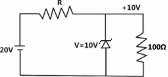
Sign in to UnlockFigure shows an electric voltage regulator. The zener diode may be assumed to require a minimum current of 25 mA for satisfactory operations. The value of R required for satisfactory voltage regulation of the circuit is
Explanation Locked!
Unlock this branch to view the explanation, track, bookmark and more.
Sign in to UnlockFigure below shows a common emitter amplifier. The quiescent collector voltage of the circuit is approximately
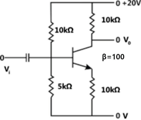

10 V
14 V
20 V
Explanation Locked!
Unlock this branch to view the explanation, track, bookmark and more.
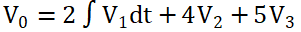
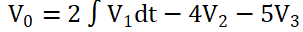
Sign in to UnlockWith ideal operational amplifiers, the circuit in figure simulates the output equation
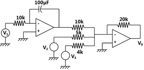
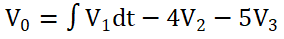
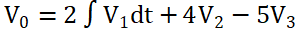
Explanation Locked!
Unlock this branch to view the explanation, track, bookmark and more.
Sign in to UnlockThe signal flow graph of figure has ____________ forward paths/and ____________ feedback loops.
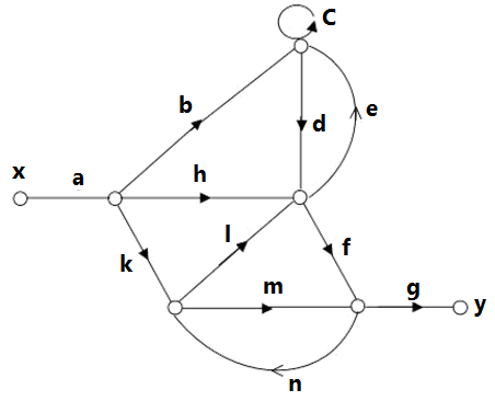
Explanation Locked!
Unlock this branch to view the explanation, track, bookmark and more.
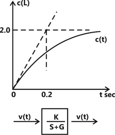
Sign in to UnlockA first order system and its response to a unit step input are shown in figure. The system parameters are
a= _______________
K= _______________
Explanation Locked!
Unlock this branch to view the explanation, track, bookmark and more.
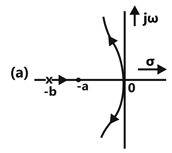
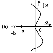
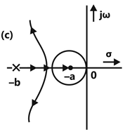
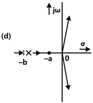
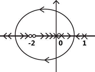
Sign in to UnlockA unity feedback system has an open-loop transfer function of the form

Which of the loci shown in figure can be valid root-loci for the system?
Explanation Locked!
Unlock this branch to view the explanation, track, bookmark and more.
Sign in to UnlockWhich of the following is the transfer function of a system having the Nyquist plot in figure?
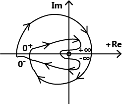


Explanation Locked!
Unlock this branch to view the explanation, track, bookmark and more.
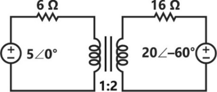
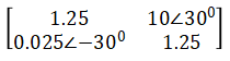
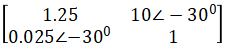
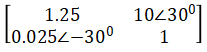
Sign in to UnlockThe terminal voltage and currents of a two-port network are indicated on the figure. If the two-port is reciprocal, then
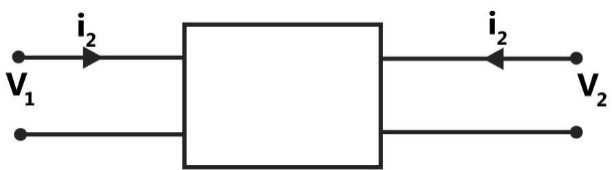


Explanation Locked!
Unlock this branch to view the explanation, track, bookmark and more.
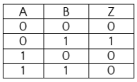
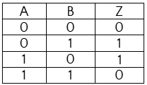
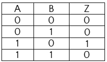
Sign in to UnlockComplete the truth table for the combinational circuit shown in figure.
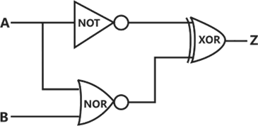

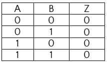
Explanation Locked!
Unlock this branch to view the explanation, track, bookmark and more.
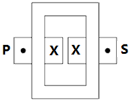
Sign in to UnlockThe relative current directions through the Primary (P) and Secondary (S) of a single phase transformer connected to a resistive load on the secondary side, are indicated in the various cross-sectional views given in figure. Which of these are correct representations


Explanation Locked!
Unlock this branch to view the explanation, track, bookmark and more.
Sign in to UnlockDamper winding is provided in a poly-phase synchronous motor in order to
Explanation Locked!
Unlock this branch to view the explanation, track, bookmark and more.
Sign in to UnlockThe resolution of an 8-bit A/D converter is ________________%
Explanation Locked!
Unlock this branch to view the explanation, track, bookmark and more.
Sign in to UnlockThe V-I characteristic as seen from the terminal pair (A,B) of the network of figure (a) is shown figure (b), if a variable resistance is connected across the terminal pair (A,B), the maximum power that can be supplied to would be

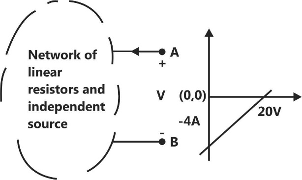
Explanation Locked!
Unlock this branch to view the explanation, track, bookmark and more.
Sign in to UnlockTwo coils having equal resistance but different inductances are connected in series.
The time-constant of the series combination is:
Explanation Locked!
Unlock this branch to view the explanation, track, bookmark and more.
Sign in to UnlockIn the figure shown, are ideal ammeters. If read 5 and 13A respectively, reading of will be


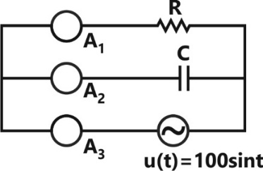
8A
12A
18A
Indeterminate unless the actual values of R, C and are specified

Explanation Locked!
Unlock this branch to view the explanation, track, bookmark and more.
Sign in to UnlockLevel compounded D.C generator is used for which of the following applications?
Explanation Locked!
Unlock this branch to view the explanation, track, bookmark and more.
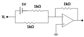
Sign in to UnlockIn figure shown, assume the Zener diode and the operational amplifier to be ideal.
( gain )

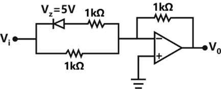
Gain characteristics

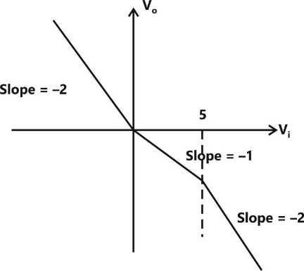
The equivalent circuit and the gain for
Gain = -2

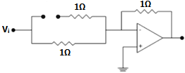
The equivalent circuit and the gain for
Gain = -1

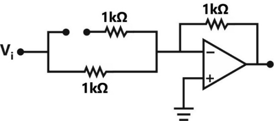
The equivalent circuit for

Explanation Locked!
Unlock this branch to view the explanation, track, bookmark and more.
Sign in to UnlockFigure shows a bridge for measuring the resistance and inductance of a choke.
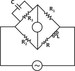
If the resistors can have a variation of and C a variation of from their nominal values, estimate the percentage error in the evaluation of R and L.


Percentage error in R =

Percentage error in L =


Explanation Locked!
Unlock this branch to view the explanation, track, bookmark and more.
Sign in to UnlockPrecautions are essential for ensuring that the secondary of a CT is not open circuited when the primary circuit carries a current because
Explanation Locked!
Unlock this branch to view the explanation, track, bookmark and more.
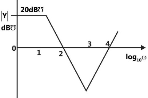
Sign in to UnlockA one port active network has an input admittance Y, the magnitude of which is shown in figure as a function of frequency. The circuit is resistive or capacitive in different frequency ranges.
Complete the following table:
Frequency Range | Type of Impedance | Value (Ω/H/F) |
10000 rad/sec < ω | A | P |
10 rad/sec < ω < 1000 rad/sec | B | Q |
Explanation Locked!
Unlock this branch to view the explanation, track, bookmark and more.
Sign in to UnlockFigure shows a common emitter amplifier
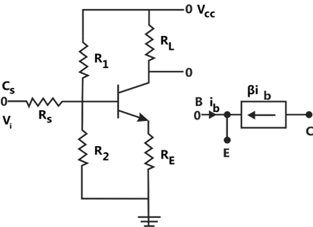
(a) Simplify the circuit by applying Thevenin’s theorem to the biasing network at the base of the transistor

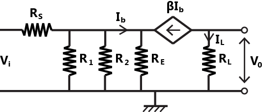
(b) Assuming to be a short for the frequency range considered. Draw the small signal a.c. model of the circuit obtained in (a) by using the simple model for the transistor shown in figure.

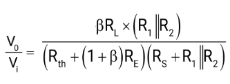
(c) Evaluate the small signal gain of the amplifier.

Small signal a.c. model


Explanation Locked!
Unlock this branch to view the explanation, track, bookmark and more.
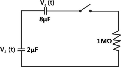
Sign in to UnlockThe switch S in figure is closed at t=0. If and respectively, voltages across the capacitors in steady state will be :


Explanation Locked!
Unlock this branch to view the explanation, track, bookmark and more.
Sign in to UnlockA 500 MVA, 11 KV synchronous generator has 0.2 p.u. synchronous reactance. The p.u. synchronous reactance on the base values of 100 MVA and 22 KV is:
Explanation Locked!
Unlock this branch to view the explanation, track, bookmark and more.
Sign in to Unlock(a) Find the transfer function
for the network shown in figure.

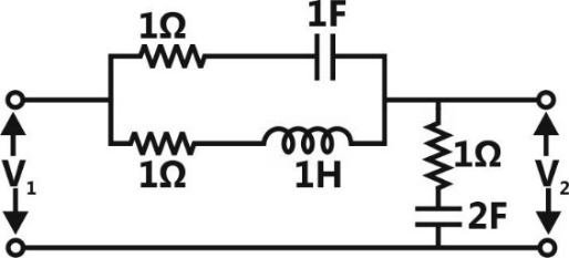
(b) What is the order of the system?
(c) Now if the inductance value is changed to 2H, what will be the order of the modified network?
order of the system = 1

order of the system = 2
order of the modified network = 3
Explanation Locked!
Unlock this branch to view the explanation, track, bookmark and more.
Sign in to UnlockA unity feedback system has the forward loop transfer function

(c) Without calculating the real-axis breakaway
points. Sketch the form of root loci for the system
Range of K for stable operation: K>2
Imaginary axis crossover points
and


Root loci for the system
Range of K for stable operation: K<2
Explanation Locked!
Unlock this branch to view the explanation, track, bookmark and more.
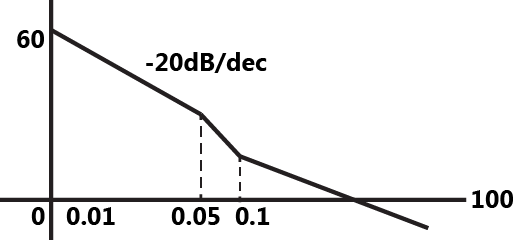
Sign in to UnlockThe system having the Bode magnitude plot shown in figure has the transfer function


Explanation Locked!
Unlock this branch to view the explanation, track, bookmark and more.
Sign in to UnlockThe hysteresis and eddy current losses of a single phase transformer working on 200V, 50 Hz supply are respectively. The percentage decrease in these, when operated on a 160V, 40 Hz supply are :

Explanation Locked!
Unlock this branch to view the explanation, track, bookmark and more.
Sign in to UnlockA prime mover drives a 6 pole, 3-phase induction frequency converter. The converter is connected to 60 Hz, 3-phase supply on the primary. If the prime mover speed is 3000 rpm, the frequencies of the possible outputs from the converter are
Explanation Locked!
Unlock this branch to view the explanation, track, bookmark and more.
Sign in to UnlockRing main distribution system is preferred to a radial system, because
Explanation Locked!
Unlock this branch to view the explanation, track, bookmark and more.
Sign in to UnlockA 100 MVA generator with 10% reactance and a 200 MVA generator with 8% reactance (reactances on their own bases) are connected as shown in figure. The fault level on bus 1 is to be restricted to 1500 MVA. Calculate, on 100 MVA base.
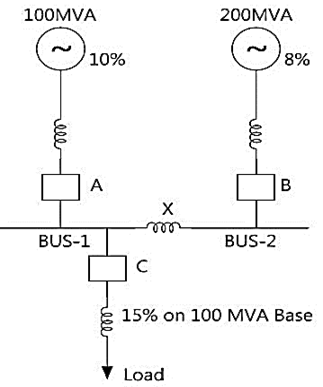
(i) The reactance of bus bar reactor X
(ii) Fault level of bus 2
(iii) MVA rating of circuit breaker C
Explanation Locked!
Unlock this branch to view the explanation, track, bookmark and more.
Sign in to UnlockA separately excited d.c. motor has to be run at 125% of rated speed when delivering 50% torque. The excitation will be _______________.
Explanation Locked!
Unlock this branch to view the explanation, track, bookmark and more.
Sign in to UnlockA 50 MVA, 132/66 kV, , three phase power transformer is protected by percentage differential relays. If the current transformers (CTs) located on the delta and wye sides of the power transformer are 300/5A and 1200/5A respectively.

Explanation Locked!
Unlock this branch to view the explanation, track, bookmark and more.
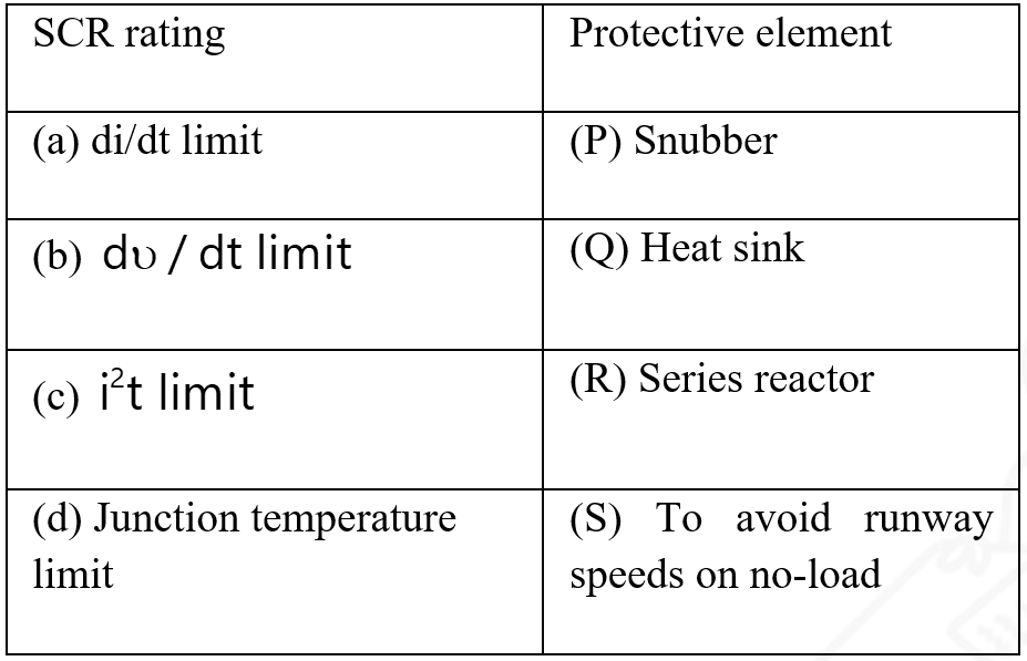
Sign in to UnlockMatch the functions of the following protective elements in SCR applications:
Explanation Locked!
Unlock this branch to view the explanation, track, bookmark and more.
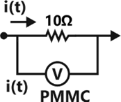
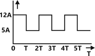
Sign in to UnlockThe current passing through a 10 Ohm resistor of figure (a) has the waveform in figure (b). The reading of the PMMC voltmeter connected across the resistor
Explanation Locked!
Unlock this branch to view the explanation, track, bookmark and more.
Sign in to UnlockA toroidal iron ring has a uniform cross-sectional area of 50, and a mean magnetic path length of 100mm. the ring has an air-gap of 1mm, the ring is excited with a dc current of 1 A through a coil of 100 turns wound uniformly along its length. The iron may be assumed to be perfect magnetic material. The effect of fringing at the gap may be assumed to increase the effective area of magnetic flux at the gap by 10%.

Evaluate
(a) The exciting mmf of the coil
(b) The effective reluctance of magnetic circuit
(c) The inductance of the coil
(d) The energy stored in the magnetic field under the above excitation.
Explanation Locked!
Unlock this branch to view the explanation, track, bookmark and more.
Sign in to UnlockMatch the windings of a large D.C series motor and their functions:
Windings | Function |
(A) series field winding | (P) to avoid field distortion under the pole |
(B) shunt field winding | (Q) to avoid sparking |
(C) commutating pole winding | (R) to generate working flux |
(D) compensating winding | (S) to avoid runway speeds on no-load |
Explanation Locked!
Unlock this branch to view the explanation, track, bookmark and more.
Sign in to UnlockThe mica layer in a parallel plate capacitor with an effective area of 120 has a damaged section equivalent to a hole of 0.5 mm diameter. Which of the following would be significantly affected by the damage?


Capacitance
Charge
Dielectric breakdown strength

Explanation Locked!
Unlock this branch to view the explanation, track, bookmark and more.
Sign in to UnlockIn figure calculate
(a) The power delivered by each source
(b) The power dissipated in each resistor
Explanation Locked!
Unlock this branch to view the explanation, track, bookmark and more.
Sign in to UnlockA 5 kW, 400 V, 50 Hz, 4 pole, delta connected three-phase induction motor is supplied by a cable of negligible inductance. On starting the motor using a star-delta starter, it is found that the starting torque is the same on star as well as delta connection, due to the voltage drop in the feeder resistance. The equivalent circuit parameters of the motor are as follows:

Determine the feeder resistance.
Explanation Locked!
Unlock this branch to view the explanation, track, bookmark and more.
Sign in to UnlockA 10 kVA, 380V, 4-pole, 50 Hz, star-connected cyclindrical rotor alternator has a stator resistance and synchronous reactance of 1 ohm and 15 ohms respectively. It supplies a load of 8 kW at rated voltage and 0.8 power factor lagging.
Explanation Locked!
Unlock this branch to view the explanation, track, bookmark and more.
Sign in to UnlockAn underdamped second-order system having a transfer function of the form has a frequency response plot shown in the figure. Then the system gain K is _______________ and the damping factor is approximately ___________________.

System gain K = 2
Damping factor

System gain K = 1
Damping factor

Explanation Locked!
Unlock this branch to view the explanation, track, bookmark and more.
Sign in to UnlockA 10 kW, 6 pole, D.C generator develops an EMF of 200V at 1500 rpm. The armature has a lap connected winding. The average flux density over a pole pitch is 0.9 Tesla. The length and diameter of the armature are 0.25m and 0.2m respectively. Calculate
(a) The flux per pole
(b) The total number of active conductors in the armature
(c) The torque developed by the machine when the armature supplies a current of 50A.
Explanation Locked!
Unlock this branch to view the explanation, track, bookmark and more.
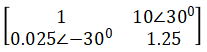
Sign in to UnlockTwo transmission lines are connected in cascade, whose ABCD parameters are

Respectively. Find the resultant ABCD parameters.
Explanation Locked!
Unlock this branch to view the explanation, track, bookmark and more.
Sign in to Unlock