
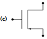
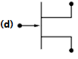
An enhancement type n-channel MOSFET is represented by the symbol


Explanation Locked!
Unlock this branch to view the explanation, track, bookmark and more.
Sign in to UnlockA rectangular current pulse of duration T and magnitude I has the Laplace transform


Explanation Locked!
Unlock this branch to view the explanation, track, bookmark and more.
Sign in to UnlockThe logic function is the same as


None of (a), (b) (c)
Explanation Locked!
Unlock this branch to view the explanation, track, bookmark and more.
Sign in to UnlockThe mobility of an electron in a conductor is expressed in terms of


Explanation Locked!
Unlock this branch to view the explanation, track, bookmark and more.
Sign in to UnlockAn industrial consumer has a daily load pattern of
2000 kW, 0.8 lag for 12 hours, and 1000 kW UPF for 12 hours. The load factor is:
Explanation Locked!
Unlock this branch to view the explanation, track, bookmark and more.
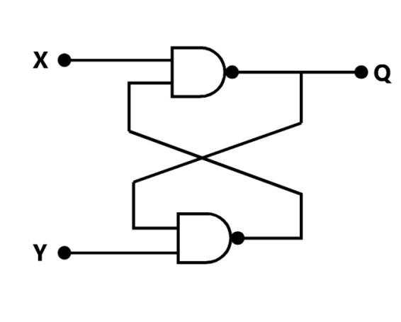
Sign in to UnlockFor a flip-flop formed from two NAND gates as shown, the unusable state corresponds to
Explanation Locked!
Unlock this branch to view the explanation, track, bookmark and more.
Sign in to UnlockThe RMS value of a half-wave rectified symmetrical square wave current of 2A is:

1A


Explanation Locked!
Unlock this branch to view the explanation, track, bookmark and more.
Sign in to UnlockAs the temperature is increased, the voltage across a diode carrying a diode carrying a constant current
Explanation Locked!
Unlock this branch to view the explanation, track, bookmark and more.
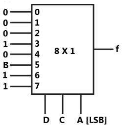
Sign in to UnlockThe logic function is to be realized using an 8 to 1 multiplexer shown in figure, using A, C and D as control inputs.

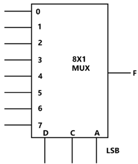
(a) Indicate the inputs to be applied at the terminals 0 to 7
(b) Can the function be realize using a 4 to 1 multiplexer? State YES or NO
(a)
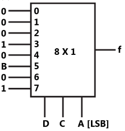
(b) No
(a)
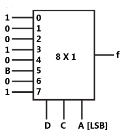
(b) No
(a)
(b) Yes
(a)
(b) No
Explanation Locked!
Unlock this branch to view the explanation, track, bookmark and more.
Sign in to UnlockA PWM switching scheme is used with a three phase inverter to
Explanation Locked!
Unlock this branch to view the explanation, track, bookmark and more.
Sign in to UnlockThe ratio error of a given A current transformer is zero when feeding 5 VA, pf burden at rated current. Estimate the iron loss of the current transformer at this operating condition if the secondary has 198 turns and a winding resistance of . Neglect leakage reactance.


Explanation Locked!
Unlock this branch to view the explanation, track, bookmark and more.
Sign in to UnlockA single channel digital storage oscilloscope uses a 10 bit, samples per second Analog-to-Digital converter. For a 100 KHz sine wave input, the number of samples taken per cycle of the input will be


Explanation Locked!
Unlock this branch to view the explanation, track, bookmark and more.
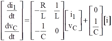
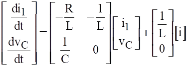
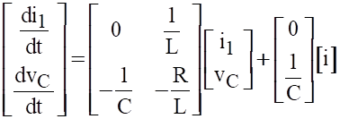
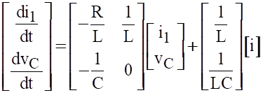
Sign in to UnlockFor the network of Figure, obtain the state equation in terms of capacitor voltage,and inductor current .


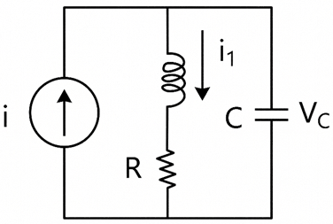
Explanation Locked!
Unlock this branch to view the explanation, track, bookmark and more.
Sign in to UnlockFor a dual ADC type digit DVM, the reference voltage is 100mV and the first integration time is set to 300ms. For some input voltage, the “de-integration” period is 370.2ms. The DVM will indicate

Explanation Locked!
Unlock this branch to view the explanation, track, bookmark and more.
Sign in to UnlockA rectangular voltage pulse of magnitude V and duration T is applied to a series combination of resistance R and capacitance C. The maximum voltage developed across the capacitor is:


v

Explanation Locked!
Unlock this branch to view the explanation, track, bookmark and more.
Sign in to UnlockFor the small signal BJT amplifier shown in fig, Assume β = 100 and Frequency =1 kHz
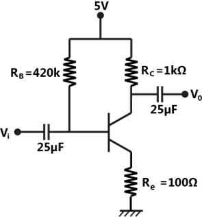
Explanation Locked!
Unlock this branch to view the explanation, track, bookmark and more.
Sign in to UnlockWhen a periodic triangular voltage peak amplitude 1V and frequency 0.5Hz is applied to a parallel combination of 1Ω resistance and 1F capacitance, the current through the voltage source has wave-form
Explanation Locked!
Unlock this branch to view the explanation, track, bookmark and more.
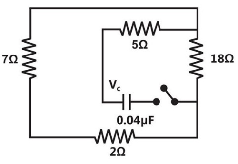
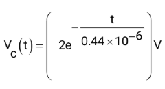
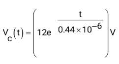
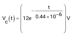
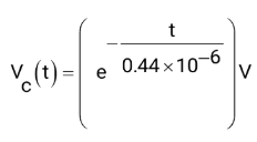
Sign in to UnlockIn the circuit shown in figure, capacitor is initially charged to 12V. Find the mathematical expression for the voltage across the capacitor after closing the switch at t=0

Explanation Locked!
Unlock this branch to view the explanation, track, bookmark and more.
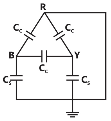
Sign in to UnlockFor the circuit shown in fig. the capacitance measured between terminals B and Y will be


Explanation Locked!
Unlock this branch to view the explanation, track, bookmark and more.
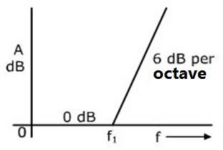
Sign in to UnlockThe function corresponding to the Bode plot of the figure is


Explanation Locked!
Unlock this branch to view the explanation, track, bookmark and more.
Sign in to UnlockThe color code of a 1kΩ resistance is:
Explanation Locked!
Unlock this branch to view the explanation, track, bookmark and more.
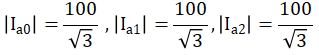
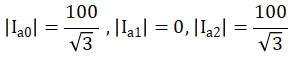
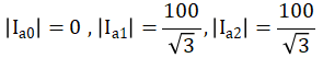
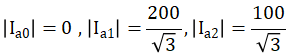
Sign in to UnlockDetermine the magnitudes of the symmetrical components of the currents in a three phase (RYB) three wire system, when a short circuit occurs between R and Y phase wires, the fault current being 100A.

Explanation Locked!
Unlock this branch to view the explanation, track, bookmark and more.
Sign in to UnlockSteady state stability of a power system is the ability of the power system to
Explanation Locked!
Unlock this branch to view the explanation, track, bookmark and more.
Sign in to UnlockWhen a resistor R is connected to a current source, it consumes a power of 18W. When the same R is connected to a voltage source having the same magnitude as the current source, the power absorbed by R is 4.5W. The magnitude of the current source and the value of R are
and


3A and

1A and 18Ω
6A and 0.5Ω
Explanation Locked!
Unlock this branch to view the explanation, track, bookmark and more.
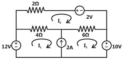
Sign in to UnlockSolve the circuit shown in figure using the mesh method of analysis and determine the mesh currents and . Evaluate the power developed in the 10V voltage source.


Explanation Locked!
Unlock this branch to view the explanation, track, bookmark and more.
Sign in to UnlockTwo parallel wires separated by a distance d are carrying a current I in the same direction. The magnetic field along a line running parallel to these wires and midway between them
Explanation Locked!
Unlock this branch to view the explanation, track, bookmark and more.
Sign in to UnlockA series R-L-C circuit when excited by a 10V sinusoidal voltage source of variable frequency, exhibits resonance at 100Hz and has a 3 dB bandwidth of 5Hz. The voltage across the inductor L at resonance is:
10V


200V
Explanation Locked!
Unlock this branch to view the explanation, track, bookmark and more.
Sign in to UnlockThree sections of a feeder are provided with circuit breakers CB1, CB2, CB3, CB4, CB5 and CB6. For a fault F as indicated in fig.

Explanation Locked!
Unlock this branch to view the explanation, track, bookmark and more.
Sign in to UnlockResonant converters are basically used to
Explanation Locked!
Unlock this branch to view the explanation, track, bookmark and more.
Sign in to UnlockAn electromagnetic field is radiated from
Explanation Locked!
Unlock this branch to view the explanation, track, bookmark and more.
Sign in to UnlockWhen the plate area of a parallel plate capacitor is increased by keeping the capacitor voltage constant, the force between the plates
Explanation Locked!
Unlock this branch to view the explanation, track, bookmark and more.
Sign in to UnlockThe current in the circuit shown in figure is:
Explanation Locked!
Unlock this branch to view the explanation, track, bookmark and more.
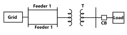
Sign in to UnlockDetermine the required MVA rating of the circuit breaker CB for the system shown in fig. Consider the grid as infinite bus. Choose 6 MVA as base.
Transformer: 3-phase, 33/11 kV, 6 MVA, 0.01+j0.08p.u. Impedance
Load: 3-phase, 11 kV, 5800 MVA, 0.8 lag, j0.2p.u. Impedance
Impedance of each feeder 9+j18 Ω
Explanation Locked!
Unlock this branch to view the explanation, track, bookmark and more.
Sign in to UnlockA three phase diode bridge is used to provide rectified output from a 400V, 50Hz, 3-phase supply to a R-L load with 10 Ω resistance and 300mH inductance.
Explanation Locked!
Unlock this branch to view the explanation, track, bookmark and more.
Sign in to UnlockCurrents , and meet at a junction (node) in a circuit. All currents are marked as entering the node.


If and , then will be


Explanation Locked!
Unlock this branch to view the explanation, track, bookmark and more.
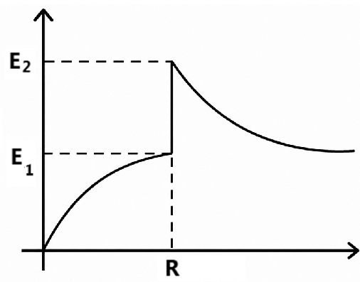
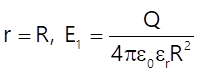
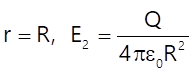
Sign in to UnlockA charge +Q uniformly distributed throughout the volume of a dielectric sphere of radius R and dielectric constant based on Gauss law, determine the expressions for the electric field E as a function of distance r from the centre of the sphere, within the ranges 0<r<R and . Indicate expression(s) for the critical point(s) on the sketch.


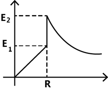
Explanation Locked!
Unlock this branch to view the explanation, track, bookmark and more.
Sign in to UnlockA fixed capacitor of reactance –j0.02 kΩ is connected in parallel across a series combination of a fixed inductor of reactance j0.01 kΩ and a variable resistance R. As R is varied from zero to infinity, the locus diagram of the admittance of this L-C-R circuit will be
Explanation Locked!
Unlock this branch to view the explanation, track, bookmark and more.
Sign in to UnlockThe voltage phasor of a circuit is and the current phasor is A. The active and the reactive powers in the circuit are:


10W and 17.32 VAr
5W and 8.66 VAr
20W and 60 VAr
and


Explanation Locked!
Unlock this branch to view the explanation, track, bookmark and more.
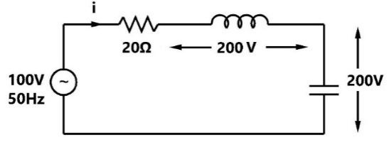
Sign in to UnlockA constant voltage frequency sinusoidal voltage source of magnitude is connected to a series circuit made of a resistance of 15Ω, a coil of winding resistance R and inductance L and a 50μF capacitor. The voltage across the 15Ω resistors is 30V, across the coil is 50V, across the capacitor is 40V, The voltage across the combination of the 15Ω resistor and the coil together is 72.11V. Determine the values of the inductance L, winding resistance R and the source voltage V.

Explanation Locked!
Unlock this branch to view the explanation, track, bookmark and more.
Sign in to UnlockHigher synchronous reactance is preferred in the present day alternators, because one can have
Explanation Locked!
Unlock this branch to view the explanation, track, bookmark and more.
Sign in to UnlockA three phase alternator is wound with a 60 degree phase-spread armature windings and develops 300 kVA. If the armature is reconnected utilizing all the coils for single phase operation with a phase spread of 180 degrees, the new rating of the machine is
Explanation Locked!
Unlock this branch to view the explanation, track, bookmark and more.
Sign in to UnlockA 5 MVA, 11 kV, 3-phase star connected alternator is synchronized to the bus bars and is operating with an induced EMF of 125% of the rated voltage. If the load current is 500A, what is the power factor of operation? The machine has a synchronous reactance of 5Ω and negligible resistance per phase.
Explanation Locked!
Unlock this branch to view the explanation, track, bookmark and more.
Sign in to UnlockA 4-pole lap-wound DC generator has a developed power of P watts and voltage of E volts. Two adjacent brushes of the machine are removed as they are worn out. If the machine operates with the remaining brushes, the developed voltage and power that can be obtained from the machine are
E, P


Explanation Locked!
Unlock this branch to view the explanation, track, bookmark and more.
Sign in to UnlockA DC shunt motor is running at 1200 rpm, when excited with 220V DC. Neglecting the losses and saturation, the speed of the motor when connected to a 175V DC supply is:
Explanation Locked!
Unlock this branch to view the explanation, track, bookmark and more.
Sign in to UnlockElectrodynamic type watt-meters have large errors while measuring power in ac circuits at low power factor conditions, since the voltage across and the current through the
Explanation Locked!
Unlock this branch to view the explanation, track, bookmark and more.
Sign in to UnlockThe input voltage in the circuit shown in fig is a 1 kHz sine wave of 1V amplitude. Assume ideal operational amplifiers with supply. Sketch on a single diagram the waveforms of the voltages and shown, indicating the peak value of and the average value


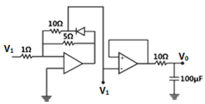
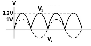
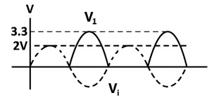
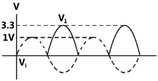
None
Explanation Locked!
Unlock this branch to view the explanation, track, bookmark and more.
Sign in to UnlockA separately excited DC shunt motor is driving a fan load whose torque is proportional to the square of the speed. When 100V are applied to the motor, the current taken by the motor is 8A, with the speed being 500 rpm. At what applied voltage does the speed reach 750 rpm and then what is the current drawn by the armature? Assume the armature circuit resistance to be 1Ω. Neglect brush and mechanical losses
Explanation Locked!
Unlock this branch to view the explanation, track, bookmark and more.
Sign in to UnlockA current of
is measured with a thermocouple type, 5A full-scale, class 1 meter. The meter reading would lie in the range


Explanation Locked!
Unlock this branch to view the explanation, track, bookmark and more.
Sign in to UnlockTwo 100μA full-scale PMMC meters are employed to construct a 10V and a 100V full scale voltmeter. These meters will have figures of merit (sensitivities) as
Explanation Locked!
Unlock this branch to view the explanation, track, bookmark and more.
Sign in to UnlockFor the circuit shown in figure, the internal resistance of the armatures as well as that of the current coil of the wattmeter are zero and the voltmeters have a very large figure of merit. is a 6A full scale moving iron type meter. is a commercial full wave rectifier type meter of full scale 5A. is a 500V meter of the peak response type. is a 300V PMMC type meter and W is an electrodynamometer type, 5A, 230V wattmeter. Determine the readings of and W.


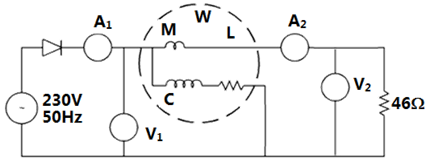
W = 563.20 W
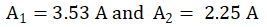
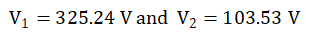
W = 573.20 W
Explanation Locked!
Unlock this branch to view the explanation, track, bookmark and more.
Sign in to UnlockThe winding of a Q kVA, volt, three-phase, Delta connected, core type transformer are reconnected to work as a single phase transformer. The maximum voltage and the power ratings of the new configuration are


Explanation Locked!
Unlock this branch to view the explanation, track, bookmark and more.
Sign in to UnlockA 10kVA, 400 V/200V single-phase transformers with 10% impedance draws a steady short circuit line current of
Explanation Locked!
Unlock this branch to view the explanation, track, bookmark and more.
Sign in to UnlockStarting torque can be obtained in the case of a single phase induction motor with identical main and auxiliary windings by connecting
Explanation Locked!
Unlock this branch to view the explanation, track, bookmark and more.
Sign in to UnlockThe percentage resistance and percentage reactance of a 10kVA, 400V/200V, 3-phase transformer are 2% and 10% respectively. If the constant losses in the machine are 1%, the maximum possible percentage efficiency of the transformer is:
Explanation Locked!
Unlock this branch to view the explanation, track, bookmark and more.
Sign in to UnlockThe following starting method for an induction motor is inferior view of the poor starting torque per ampere of the line current drawn:
Explanation Locked!
Unlock this branch to view the explanation, track, bookmark and more.
Sign in to UnlockA 400V/100V, 10 kVA two-winding transformer is reconnected as an auto-transformer across a suitable voltage source. The maximum rating of such an arrangement could be
Explanation Locked!
Unlock this branch to view the explanation, track, bookmark and more.
Sign in to UnlockA 3 kW, 400V/200V, Delta/Star, 50Hz, three phase, 6-pole induction motor is found to draw a line current of 25A at a power factor of 0.4, when a blocked rotor test is conducted at the rated voltage. The stator and rotor winding resistances in ohms per phase are A and B, if the torque developed by the motor under the above conditions is 25 N-m. Find A+B=
Explanation Locked!
Unlock this branch to view the explanation, track, bookmark and more.
Sign in to UnlockA 10 kVA, 400V/200V, single transformer with a percentage resistance of 3% and percentage reactance of 6% is supplying a current of 50A to a resistive load. The value of the load voltage is:
Explanation Locked!
Unlock this branch to view the explanation, track, bookmark and more.
Sign in to UnlockTwo single-phase transformers A and B have the following parameters:
Transformer A: 10V/200V, percentage resistance and percentage reactance 3% and 4% respectively.
Transformer B: 5 kVA, 400V/200V, percentage resistance and percentage reactance are 4% and 3% respectively.
These two transformers are connected in parallel and they share a common load of 12 kW at a power factor of 0.8 lagging. Determine the active and reactive power delivered by the transformer A.


Explanation Locked!
Unlock this branch to view the explanation, track, bookmark and more.
Sign in to UnlockAn overhead line having a surge impedance of 400Ω is connected in series with an underground cable having a surge impedance of 100Ω. If a surge of 50kV travels from the line end towards the line-cable junctions, the value of the transmitted voltage wave at the junction is:
Explanation Locked!
Unlock this branch to view the explanation, track, bookmark and more.
Sign in to UnlockThe load carrying capability of a long AC transmission line is:
Explanation Locked!
Unlock this branch to view the explanation, track, bookmark and more.
Sign in to UnlockCorona losses are minimized when
Explanation Locked!
Unlock this branch to view the explanation, track, bookmark and more.
Sign in to UnlockIn a DC transmission line
Explanation Locked!
Unlock this branch to view the explanation, track, bookmark and more.
Sign in to UnlockFor a single phase overhead line having solid copper conductors of diameter 1cm, spaced 60cm between centers, the inductance in mH/km is:


Explanation Locked!
Unlock this branch to view the explanation, track, bookmark and more.
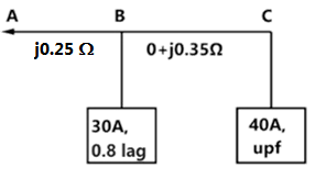
Sign in to UnlockA single phase AC distributor supplies two single phase loads as shown in fig. The voltage drop from A to C is:
Explanation Locked!
Unlock this branch to view the explanation, track, bookmark and more.
Sign in to UnlockA 220kV, 20 km long , 3-phase transmission line has the following A, B, C, D constants. , ,


11A
220A

Explanation Locked!
Unlock this branch to view the explanation, track, bookmark and more.
Sign in to UnlockA 3-phase, 11kV, 50 Hz, 200 kW load has a power factor of 0.8lag. A delta connected 3-phase capacitor is used to improve the power factor to unity. The capacitance power phase of the capacitor in microfarads is
Explanation Locked!
Unlock this branch to view the explanation, track, bookmark and more.
Sign in to UnlockA 6.6kV, 50Hz, single core lead-sheathed cable has the following data:
Conductor diameter: 1.5cm, length: 4km
Internal diameter of the sheath: 3cm
Resistivity of insulation:

Relative permittivity of insulation: 3.5
Calculate:
(a) The insulation resistance
(b) The capacitance and
(c) The maximum electric stress in the insulation
Explanation Locked!
Unlock this branch to view the explanation, track, bookmark and more.
Sign in to UnlockA 66 kV, 3-phase, 50Hz, 150km long overhead transmission line is open circuited at the receiving end. Each conductor has a resistance of 0.25 Ω/km, an inductive reactance of 0.5 Ω/km and a capacitive admittance to neutral of

Draw the nominal π-equivalent circuit and Calculate the receiving end voltage (kV) if the sending end voltage is 66kV
Explanation Locked!
Unlock this branch to view the explanation, track, bookmark and more.
Sign in to UnlockIn a transmission line each conductor is at 20 kV and is supported by a string of 3 suspension insulators. The air capacitance between each cap-pin junction and tower is one-fifth of the capacitance C of each insulator unit. A guard ring, effective only over the line-end insulator unit is fitted so that the voltages on the two units nearest the line-end are equal
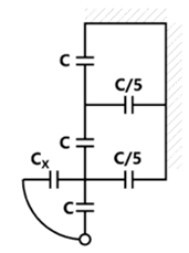
(a) Calculate the voltage on the line-end unit
(b) Calculate the value of capacitance required

Explanation Locked!
Unlock this branch to view the explanation, track, bookmark and more.
Sign in to Unlock