
The octal equivalent of the HEX number AB.CD is
Explanation Locked!
Unlock this branch to view the explanation, track, bookmark and more.
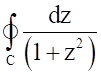
Sign in to UnlockThe value of where C is the contour is


Explanation Locked!
Unlock this branch to view the explanation, track, bookmark and more.
Sign in to UnlockLet a signal be applied to a stable linear lime-invariant system. Let the corresponding steady state output be represented as. Then which of the following statements is true?


F is not necessarily a "sine" or "cosine" function but must be periodic with.

F must be a "sine" or "cosine" function with

F must be a "sine" function with and

F must be a "sine" or “cosine” function with
Explanation Locked!
Unlock this branch to view the explanation, track, bookmark and more.
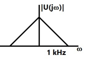
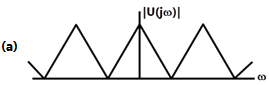
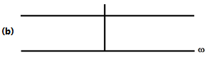
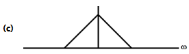
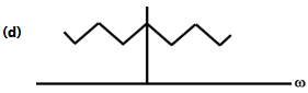
Sign in to UnlockThe frequency spectrum of a signal is shown in the figure. If this signal is ideally sampled at intervals of 1ms. Then the frequency spectrum of the sampled signal will be
Explanation Locked!
Unlock this branch to view the explanation, track, bookmark and more.
Sign in to UnlockA voltage source inverter is used to control the speed of a three-phase, 50 Hz, squirrel cage induction motor. Its slip for rated torque is 4%. The flux is maintained at rated value. If the stator resistance and rotational losses are neglected, then the frequency of the impressed voltage to obtain the rated torque at starting should be
Explanation Locked!
Unlock this branch to view the explanation, track, bookmark and more.
Sign in to UnlockConsider the discrete-time system shown in the figure where the impulse response of G(z) is g(0) = 0, g(1) = g(2) = 1, g(3) = g(4) = ……. = 0
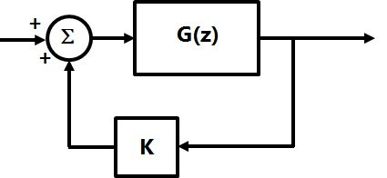
This system is stable for range of values of K


Explanation Locked!
Unlock this branch to view the explanation, track, bookmark and more.
Sign in to UnlockThe matrix A given below is the node incidence matrix of a network. The columns correspond to branches of the network while the rows correspond to nodes. Let denote the vector of branch voltages while that of branch currents. The vector denotes the vector of node voltages relative to a common ground.


Which of the following statements is true?
The equations ,


are KVL equations for the network for some loops.
The equations ,


are KVL equations for the network for some loops.
E = AV
AV = 0 are KVL equations for the network.
Explanation Locked!
Unlock this branch to view the explanation, track, bookmark and more.
Sign in to UnlockThe differential equation is discretized using Euler's numerical integration method with a time step ΔT > 0. What is the maximum permissible value of ΔT to ensure stability of the solution of the corresponding discrete time equation?

1


Explanation Locked!
Unlock this branch to view the explanation, track, bookmark and more.
Sign in to UnlockA loaded dice has following probability distribution of occurrences
Dice value | 1 | 2 | 3 | 4 | 5 | 6 |
Probability |


If three identical dice as the above are thrown, the probability of occurrence of values
1, 5 and 6 on the three dice is
Same as that of occurrence of 3, 4, 5
Same as that of occurrence of 1, 2, 5


Explanation Locked!
Unlock this branch to view the explanation, track, bookmark and more.
Sign in to Unlock, are Z-transforms of two signals x[n], y[n] respectively. A linear time invariant system has the impulse response h[n] defined by these two signals as , where * denotes discrete time convolution. Then the output of the system for the input


Has Z-transform


Has Z-transform

Does not satisfy any of the above three.
Explanation Locked!
Unlock this branch to view the explanation, track, bookmark and more.
Sign in to UnlockThe system is to be compensated such that its gain-crossover frequency becomes same as its uncompensated phase-crossover frequency and provides a 45° phase margin. To achieve this, one may use

A lag compensator that provides an attenuation of 20 dB and a phase lag of 45° at the frequency of rad/s

A lead compensator that provides an amplification of 20 dB and a phase lead of 45° at the frequency of 3 rad/s
A lag-lead compensator that provides an amplification of 20 dB and a phase lag of 45° at the frequency of rad/s

A lag-lead compensator that provides an attenuation of 20 dB and a phase lag of 45° at the frequency of 3 rad/s
Explanation Locked!
Unlock this branch to view the explanation, track, bookmark and more.
Sign in to UnlockA signal is processed by a causal filter with transfer function G(s). For a distortion free output signal waveform, G(s) must
Explanation Locked!
Unlock this branch to view the explanation, track, bookmark and more.
Sign in to UnlockIf u(t), r(t) denote the unit step and unit ramp functions respectively and u(t)*r(t) their convolution. Then the function u(t+1)*r(t−2) is given by


None of the above.
Explanation Locked!
Unlock this branch to view the explanation, track, bookmark and more.
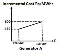
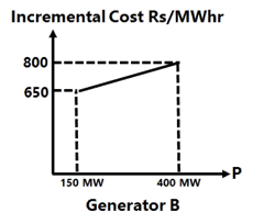
Sign in to UnlockThe incremental cost curves in Rs/MWhr for two generators supplying a common load of 700 MW are shown in the figures. The maximum and minimum generation limits are also indicated. The optimum generation schedule is:
Explanation Locked!
Unlock this branch to view the explanation, track, bookmark and more.
Sign in to UnlockDivergence of the vector field
is


None of these
Explanation Locked!
Unlock this branch to view the explanation, track, bookmark and more.
Sign in to Unlockis a low-pass digital filter with a phase characteristics same as that of the above question if


Explanation Locked!
Unlock this branch to view the explanation, track, bookmark and more.
Sign in to UnlockA bridge circuit is shown in the figure below. Which one of the sequences given below is most suitable for balancing the bridge?
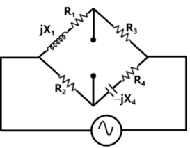
First adjust , and then adjust


First adjust , and then adjust


First adjust , and then adjust
First adjust , and then adjust
Explanation Locked!
Unlock this branch to view the explanation, track, bookmark and more.
Sign in to UnlockThe integral equals


0


Explanation Locked!
Unlock this branch to view the explanation, track, bookmark and more.
Sign in to UnlockA signal x(t) is given by

Which among the following gives the fundamental Fourier term of x(t)?


Explanation Locked!
Unlock this branch to view the explanation, track, bookmark and more.
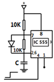
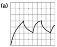
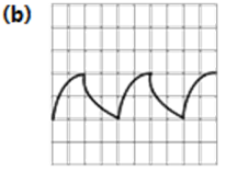
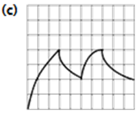
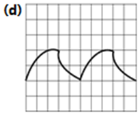
Sign in to UnlockIC 555 in the adjacent figure is configured as an Astable multi-vibrator. It is enabled to oscillate at t=0 by applying a high input to pin 4. The pin description is: 1 and 8 − supply: 2-trigger; 4-reset; 6-threshold; 7-discharge. The waveform appearing across the capacitor starting from t=0, as observed on a storage CRO is
Explanation Locked!
Unlock this branch to view the explanation, track, bookmark and more.
Sign in to UnlockA three-phase, three-stack, variable reluctance step motor has 20 poles on each rotor and stator stack. The step angle of this step motor is
Explanation Locked!
Unlock this branch to view the explanation, track, bookmark and more.
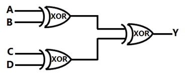
Sign in to UnlockA, B, C and D are input bits, and Y is the output bit in the XOR gate circuit of the figure below. Which of the following statements about the sum S of A. B, C, D and Y is correct?
Explanation Locked!
Unlock this branch to view the explanation, track, bookmark and more.
Sign in to UnlockThe probes of a non-isolated, two-channel oscilloscope are clipped to points A. B and C in the circuit of the adjacent figure Vin is a square wave of a suitable low frequency. The display on Ch1 and Ch2 are as shown on the right. Then the “Signal” and “Ground” probes S1, G1 and S2, G2 of Ch1 and Ch2 respectively are connected to points
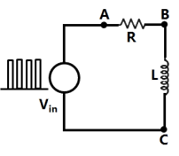
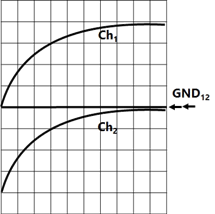
Explanation Locked!
Unlock this branch to view the explanation, track, bookmark and more.
Sign in to Unlock"Six MOSFETs connected in a bridge configuration (having no other power device) MUST be operated as a Voltage Source Inverter (VSI)'". This statement is
Explanation Locked!
Unlock this branch to view the explanation, track, bookmark and more.
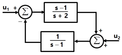
Sign in to UnlockThe system shown in figure below,
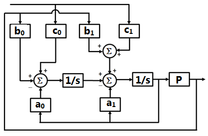
Can be reduced to the form
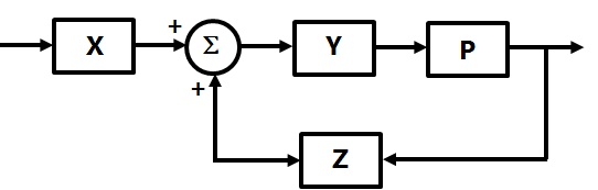
With


Explanation Locked!
Unlock this branch to view the explanation, track, bookmark and more.
Sign in to UnlockA single-phase voltage source inverter is controlled in a single pulse-width modulated mode with a pulse width of 150° in each half cycle. Total harmonic distortion is defined as , where is the RMS value of the fundamental component of the output voltage. The THD of output AC voltage waveform is


Explanation Locked!
Unlock this branch to view the explanation, track, bookmark and more.
Sign in to UnlockThe system shown in the figure is
Stable
Unstable
Conditionally stable
Stable for input , but unstable for input


Explanation Locked!
Unlock this branch to view the explanation, track, bookmark and more.
Sign in to UnlockThe figure below shows a three phase self-commutated voltage source converter connected to a power system. The converter's dc bus capacitor is marked as C in the figure. The circuit is initially operating in steady state with δ = 0 and the capacitor dc voltage is equal to . You may neglect all losses and harmonics. What action should be taken to increase the capacitor dc voltage slowly to a new steady slate value?


Explanation Locked!
Unlock this branch to view the explanation, track, bookmark and more.
Sign in to UnlockIf the loop gain K of a negative feedback system having a loop transfer function is to be adjusted to induce a sustained oscillation then

The frequency of this oscillation must be rad/s

The frequency of this oscillation must be 4 rad/s
The frequency of this oscillation must be 4 or rad/s
Such a K does not exist
Explanation Locked!
Unlock this branch to view the explanation, track, bookmark and more.
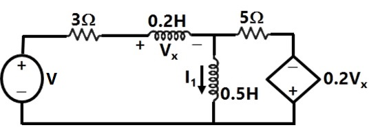
Sign in to UnlockThe state equation for the current , shown in the network shown below in terms of the voltage , and the independent source V, is given by


Explanation Locked!
Unlock this branch to view the explanation, track, bookmark and more.
Sign in to Unlockis an n-tuple nonzero vector. The n × n matrix


Explanation Locked!
Unlock this branch to view the explanation, track, bookmark and more.
Sign in to UnlockLet x and y be two vectors in a 3 dimensional space and <x, y> denote their dot product. Then the determinant

Explanation Locked!
Unlock this branch to view the explanation, track, bookmark and more.
Sign in to UnlockWhich one of the following statements regarding the INT (interrupt) and the BRQ (bus request) pins in a CPU is true?
Explanation Locked!
Unlock this branch to view the explanation, track, bookmark and more.
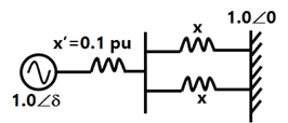
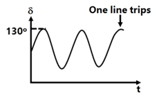
Sign in to UnlockConsider a synchronous generator connected to an infinite bus by two identical parallel transmission lines. The transient reactance x' of the generator is 0.1pu and the mechanical power input to it is constant at 1.0pu. Due to some previous disturbance, the rotor angle (δ) is undergoing an un-damped oscillation, with the maximum value of equal to . One of the parallel lines trips due to relay mal-operation at an instant when · as shown in the figure. The maximum value of the per unit line reactance, x, such that the system does not lose synchronism subsequent to this tripping is


Explanation Locked!
Unlock this branch to view the explanation, track, bookmark and more.
Sign in to UnlockThe linear operation L(x) is defined by the cross product , where and are three dimensional vectors. The 3×3 matrix M of this operation satisfies


Then the Eigen values of M are
Explanation Locked!
Unlock this branch to view the explanation, track, bookmark and more.
Sign in to UnlockThe associated figure shows the two types of rotate right instructions R1, R2 available in a microprocessor where Reg is a 8-bit register and C is the carry bit. The rotate left instructions L1 and L2 are similar except that C now links the most significant bit of Reg instead of the least significant one.

Suppose Reg contains the 2's complement number 11010110. If this number is divided by 2 the answer should be
Explanation Locked!
Unlock this branch to view the explanation, track, bookmark and more.
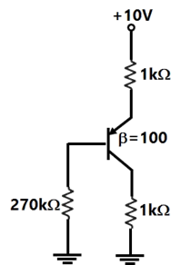
Sign in to UnlockThe common emitter forward current gain of the transistor shown is .

The transistor is operating in
Explanation Locked!
Unlock this branch to view the explanation, track, bookmark and more.
Sign in to UnlockCayley-Hamilton Theorem states that a square matrix satisfies its own characteristic equation.
Consider a matrix

A satisfies the relation


Explanation Locked!
Unlock this branch to view the explanation, track, bookmark and more.
Sign in to UnlockThe associated figure shows the two types of rotate right instructions R1, R2 available in a microprocessor where Reg is a 8-bit register and C is the carry bit. The rotate left instructions L1 and L2 are similar except that C now links the most significant bit of Reg instead of the least significant one.
Such a division can be correctly performed by the following set of operations
Explanation Locked!
Unlock this branch to view the explanation, track, bookmark and more.
Sign in to UnlockA 3 V dc supply with an internal resistance of 2Ω supplies a passive non-linear resistance characterized by the relation. The power dissipated in the non linear resistance is

Explanation Locked!
Unlock this branch to view the explanation, track, bookmark and more.
Sign in to UnlockCayley-Hamilton Theorem states that a square matrix satisfies its own characteristic equation.
Consider a matrix
equals


Explanation Locked!
Unlock this branch to view the explanation, track, bookmark and more.
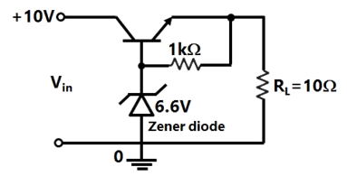
Sign in to UnlockThe three-terminal linear voltage regulator is connected to a load resistor as shown in the figure. If is 10 V, what is the power dissipated in the transistor?


Explanation Locked!
Unlock this branch to view the explanation, track, bookmark and more.
Sign in to UnlockA solid sphere made of insulating material has a radius R and has a total charge Q distributed uniformly in its volume. What is the magnitude of the electric field intensity, E, at a distance r (0<r<R) inside the sphere?


Explanation Locked!
Unlock this branch to view the explanation, track, bookmark and more.
Sign in to UnlockAn inductor designed with 400 turns coil wound on an iron core of cross sectional area and with a cut of an air gap length of 1mm. The coil is connected to a 230 V, 50 Hz AC supply. Neglect coil resistance, core loss, iron reluctance and leakage inductance


The current in the inductor is
Explanation Locked!
Unlock this branch to view the explanation, track, bookmark and more.
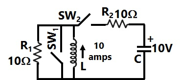
Sign in to UnlockIn the circuit shown in figure switch \(SW_1\), is initially CLOSED and \(SW_2\) is OPEN. The inductor L carries a current of 10A and the capacitor is charged to 10 V with polarities as indicated. \(SW_2\), is initially CLOSED at and \(SW_1\), is OPENED at t=0. The current through C and the voltage across L at is

Explanation Locked!
Unlock this branch to view the explanation, track, bookmark and more.
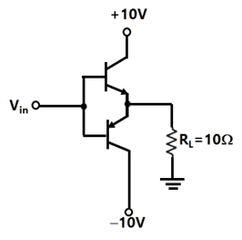
Sign in to UnlockThe input signal shown in the figure is a 1 kHz square wave voltage that alternates between +7V and −7V with a 50% duty cycle. Both transistors have the same current gain, which is large. The circuit delivers power to the load resistor . What is the efficiency of this circuit for the given input? Choose the closest answer.


Explanation Locked!
Unlock this branch to view the explanation, track, bookmark and more.
Sign in to UnlockAn inductor designed with 400 turns coil wound on an iron core of cross sectional area and with a cut of an air gap length of 1mm. The coil is connected to a 230 V, 50 Hz AC supply. Neglect coil resistance, core loss, iron reluctance and leakage inductance


The average force on the core to reduce the air gap will be
Explanation Locked!
Unlock this branch to view the explanation, track, bookmark and more.
Sign in to UnlockIf and then for , the Nyquist plot for becomes asymptotic to the line


x = 0


Explanation Locked!
Unlock this branch to view the explanation, track, bookmark and more.
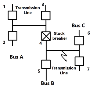
Sign in to UnlockConsider the protection system shown in the figure below. The circuit breakers, numbered from 1 to 7 are of identical type. A single line 10 ground fault with zero fault impedance occurs at the midpoint of the line (at point F), but circuit breaker 4 fails to operate ("stuck breaker"). If the relays are coordinated correctly, a valid sequence of circuit breaker operations is
Explanation Locked!
Unlock this branch to view the explanation, track, bookmark and more.
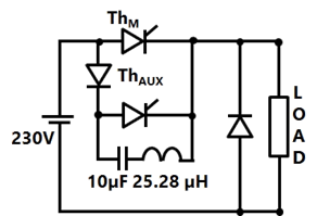
Sign in to UnlockThe circuit in the figure is a current commutated dc-dc chopper where. is the main SCR and is the auxiliary SCR. The load current is constant at 10A. is ON. is triggered at t = 0. is turned OFF between


Explanation Locked!
Unlock this branch to view the explanation, track, bookmark and more.
Sign in to UnlockA 1:1 Pulse Transformer (PT) is used to trigger the SCR in the adjacent figure. The SCR is rated at 1.5 kV,250A with 250mA, 150mA, and 150mA, 100mA. The SCR is connected to an inductive load, where L = 150mH in series with a small resistance and the supply voltage is 200V dc. The forward drops of all transistors/diodes and gate-cathode junction during ON state are 1.0 V


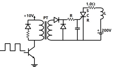
The resistance R should be
Explanation Locked!
Unlock this branch to view the explanation, track, bookmark and more.
Sign in to UnlockA 1:1 Pulse Transformer (PT) is used to trigger the SCR in the adjacent figure. The SCR is rated at 1.5 kV,250A with 250mA, 150mA, and 150mA, 100mA. The SCR is connected to an inductive load, where L = 150mH in series with a small resistance and the supply voltage is 200V dc. The forward drops of all transistors/diodes and gate-cathode junction during ON state are 1.0 V
The minimum approximate volt-second rating of the pulse transformer suitable for triggering the SCR should be: (volt-second rating is the maximum of product of the voltage and the width of the pulse that may be applied)
Explanation Locked!
Unlock this branch to view the explanation, track, bookmark and more.
Sign in to UnlockConsider the feedback control system shown below which is subjected to a unit step input. The system is stable and has the following parameters and


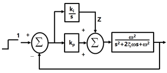
The steady state value of z is
Explanation Locked!
Unlock this branch to view the explanation, track, bookmark and more.
Sign in to UnlockConsider the R-L-C circuit shown in figure.
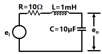
For a step-input, the overshoot in the output will be


Explanation Locked!
Unlock this branch to view the explanation, track, bookmark and more.
Sign in to UnlockConsider the R-L-C circuit shown in figure.
If the above step response is to be observed on a non-storage CRO, then it would be best to have the , as a

Explanation Locked!
Unlock this branch to view the explanation, track, bookmark and more.
Sign in to UnlockA three phase balanced star connected voltage source with frequency to rad/s is connected to a star connected balanced load which is purely inductive. The instantaneous line currents and phase to neutral voltages are denoted by and respectively, and their RMS values are denoted by V and I.


If,

then the magnitude of R is
Explanation Locked!
Unlock this branch to view the explanation, track, bookmark and more.
Sign in to UnlockA single-phase fully controlled thyristor bridge ac-dc converter is operating at a firing angle of 25° and an overlap angle of 10° with constant dc output current of 20 A. The fundamental power factor (displacement factor) al input ac mains is
Explanation Locked!
Unlock this branch to view the explanation, track, bookmark and more.
Sign in to UnlockA three-phase, fully-controlled thyristor bridge converter is used as line commutated inverter to feed 50 kW power at 420 V dc to a three-phase, 415V (line), 50 Hz ac mains. Consider dc link current to be constant. The RMS Current of the thyristor is
Explanation Locked!
Unlock this branch to view the explanation, track, bookmark and more.
Sign in to UnlockSuppose we define a sequence transformation between "a-b-c" and "p-n-o" variables as follows:
where and k is a constant. Now, if it is given that:


then,


Explanation Locked!
Unlock this branch to view the explanation, track, bookmark and more.
Sign in to UnlockA single phase full-wave half-controlled bridge convener feeds an inductive load. The two SCRs in the converter are connected to a common DC bus. The converter has to have a freewheeling diode
Explanation Locked!
Unlock this branch to view the explanation, track, bookmark and more.
Sign in to UnlockA three-phase, 440 V, 50 Hz ac mains fed thyristor bridge is feeding a 440 V dc, 15 kW, 1500 rpm separately excited dc motor with a ripple free continuous current in the dc link under all operating conditions. Neglecting the losses, the power factor of the ac mains at half the rated speed, is
Explanation Locked!
Unlock this branch to view the explanation, track, bookmark and more.
Sign in to UnlockA single-phase, 230V, 50 Hz ac mains fed step down transformer (4:1) is supplying power to a half-wave uncontrolled ac-dc converter used for charging a battery (12 V dc) with the series current limiting resistor being 19.04 Ω. The charging current is
Explanation Locked!
Unlock this branch to view the explanation, track, bookmark and more.
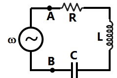
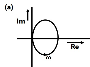
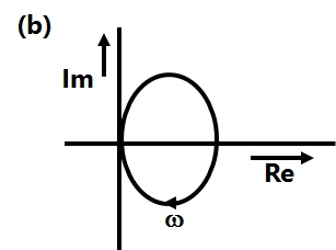
Sign in to UnlockThe R-L-C series circuit shown is supplied from a variable frequency voltage source. The admittance-locus of the R-L-C network at terminals AB for increasing frequency ω is
Explanation Locked!
Unlock this branch to view the explanation, track, bookmark and more.
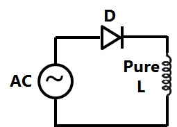
Sign in to UnlockIn the circuit of adjacent figure the diode connects the ac source to a pure inductance L.
The diode conducts for
Explanation Locked!
Unlock this branch to view the explanation, track, bookmark and more.
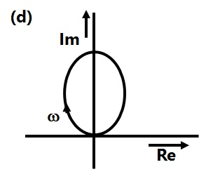
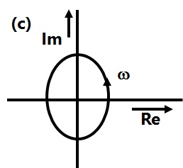
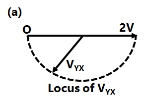
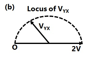
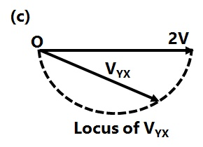
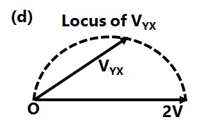
Sign in to UnlockIn the figure given below all phasors are with reference to the potential at point "O". The locus of voltage phasor as R is varied from zero to infinity is shown by

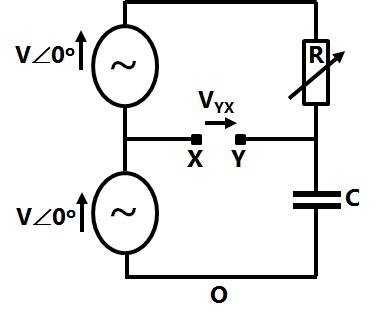
Explanation Locked!
Unlock this branch to view the explanation, track, bookmark and more.
Sign in to UnlockThe circuit shown in the figure is
A voltage source with voltage

A voltage source with voltage

A current source with current

A current source with current

Explanation Locked!
Unlock this branch to view the explanation, track, bookmark and more.
Sign in to UnlockThe switch S in the circuit of the figure is initially closed. It is opened at time t = 0. You may neglect the Zener diode forward voltage drops. What is the behavior of for t > 0?

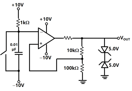
Explanation Locked!
Unlock this branch to view the explanation, track, bookmark and more.
Sign in to UnlockThe dc motor, which can provide zero speed regulation at full load without any controller, is
Explanation Locked!
Unlock this branch to view the explanation, track, bookmark and more.
Sign in to UnlockA three-phase synchronous motor connected to ac mains is running at full load and unity power factor. If its shaft load is reduced by half, with field current held constant, its new power factor will be
Explanation Locked!
Unlock this branch to view the explanation, track, bookmark and more.
Sign in to UnlockA 100 kVA, 415V (line), star-connected synchronous machine generates rated open circuit voltage of 415 V at a field current of 15 A. The short circuit armature current at a field current of 10A is equal to the rated armature current. The per unit saturated synchronous reactance is
Explanation Locked!
Unlock this branch to view the explanation, track, bookmark and more.
Sign in to UnlockAn isolated 50 Hz synchronous generator is rated at 15 MW which is also the maximum continuous power limit of its prime mover. It is equipped with a speed governor with 5% droop. Initially, the generator is feeding three loads of 4 MW each at 50 Hz. One of these loads is programmed to trip permanently if the frequency falls below 48 Hz. If an additional load of 3.5 MW is connected then the frequency will settle down to
Explanation Locked!
Unlock this branch to view the explanation, track, bookmark and more.
Sign in to UnlockIn a transformer zero voltage regulation at full load is
Explanation Locked!
Unlock this branch to view the explanation, track, bookmark and more.
Sign in to UnlockA single-phase 50kVA, 250V/500V two winding transformer has an efficiency of 95% at full load, unity power factor. If it is reconfigured as a 500V/750V autotransformer, its efficiency at its new rated load at unity power factor will be
Explanation Locked!
Unlock this branch to view the explanation, track, bookmark and more.
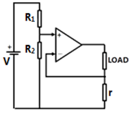
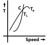
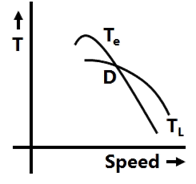
Sign in to UnlockThe electromagnetic torque of a drive, and its connected load torque are as shown below. Out of the operating points A, B, C and D, the stable ones are


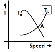
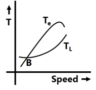
Explanation Locked!
Unlock this branch to view the explanation, track, bookmark and more.
Sign in to UnlockA three-phase squirrel cage induction motor has a starting torque of 150% and a maximum torque of 300% with respect to rated torque at rated voltage and rated frequency. Neglect the stator resistance and rotational losses. The value of slip for maximum torque
Explanation Locked!
Unlock this branch to view the explanation, track, bookmark and more.
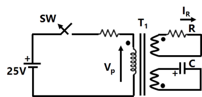
Sign in to UnlockIn the figure, transformer , has two secondary, all three windings having the same number of tums and with polarities as indicated. One secondary is shorted by a 10 Ω resistor R, and the other by a 15 µF capacitor. The switch SW is opened (t = 0) when the capacitor is charged to 5V with the left plate as positive. At t=0+ the voltage and current are


Explanation Locked!
Unlock this branch to view the explanation, track, bookmark and more.
Sign in to UnlockA three phase squirrel cage induction motor has a starting current of seven times the full load current and full load slip of 5%.
If an autotransformer is used for reduced voltage starting to provide 1.5 per unit starting torque, the autotransformer ratio (%) should be
Explanation Locked!
Unlock this branch to view the explanation, track, bookmark and more.
Sign in to UnlockA three phase squirrel cage induction motor has a starting current of seven times the full load current and full load slip of 5%.
If a star-delta starter is used to start this induction motor, the per unit starting torque will be
Explanation Locked!
Unlock this branch to view the explanation, track, bookmark and more.
Sign in to UnlockA three phase squirrel cage induction motor has a starting current of seven times the full load current and full load slip of 5%.
If a starting torque of 0.5 per unit is required then the per unit starting current should be
Explanation Locked!
Unlock this branch to view the explanation, track, bookmark and more.
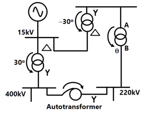
Sign in to UnlockConsider the transformer connections in a part of a power system shown in the figure. The nature of transformer connections and phase shifts are indicated for all but one transformer. Which of the following connections, and the corresponding phase shift , should be used for the transformer between A and B?


Explanation Locked!
Unlock this branch to view the explanation, track, bookmark and more.
Sign in to UnlockTwo regional systems, each having several synchronous generators and loads are interconnected by an ac line and a HVDC link as shown in the figure. Which of the following statements is true in the steady state:
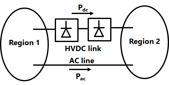
Both regions need not have the same frequency.
The total power now between the regions can be changed by controlling the HVDC converters alone.

The power sharing between the ac line and the HVDC link can be changed by controlling the HVDC converters alone.
The direction of power now in the HVDC link cannot be reversed.

Explanation Locked!
Unlock this branch to view the explanation, track, bookmark and more.
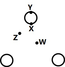
Sign in to UnlockConsider a bundled conductor of an overhead line, consisting of three identical sub-conductors placed at the corners of an equilateral triangle as shown in the figure. If we neglect the charges on the other phase conductors and ground, and assume that spacing between sub-conductors is much larger than their radius, the maximum electric field intensity is experienced at
Explanation Locked!
Unlock this branch to view the explanation, track, bookmark and more.
Sign in to UnlockThe total reactance and total susceptance of a lossless overhead EHV line, operating at 50 Hz. are given by 0.045pu and 1.2pu respectively. If the velocity of wave propagation is , then the approximate length of the line is

Explanation Locked!
Unlock this branch to view the explanation, track, bookmark and more.
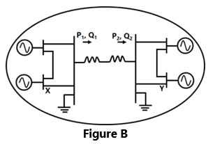
Sign in to UnlockConsider the two power systems shown in figure A below, which are initially not interconnected, and are operating in steady state at the same frequency. Separate load flow solutions are computed individually for the two systems, corresponding to this scenario. The bus voltage phasors so obtained are indicated on figure A. These two isolated systems are now interconnected by a short transmission line as shown in figure B, and it is found that.

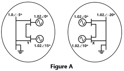
The bus voltage phase angular difference between generator bus X and generator bus Y after the interconnection is


Explanation Locked!
Unlock this branch to view the explanation, track, bookmark and more.
Sign in to UnlockA 230 V (Phase). 50 Hz, three-phase, 4-wire system has a phase sequence ABC. A unity power-factor load of 4 kW is connected between phase A and neutral N. It is desired to achieve zero neutral current through the use of a pure inductor and a pure capacitor in the other two phases. The value of inductor and capacitor is
Explanation Locked!
Unlock this branch to view the explanation, track, bookmark and more.
Sign in to Unlock