
An average-reading digital multi meter reads 10V when fed with a triangular wave, symmetric about the time-axis. For the same input an rms-reading meter will read


Explanation Locked!
Unlock this branch to view the explanation, track, bookmark and more.
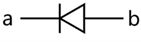
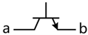
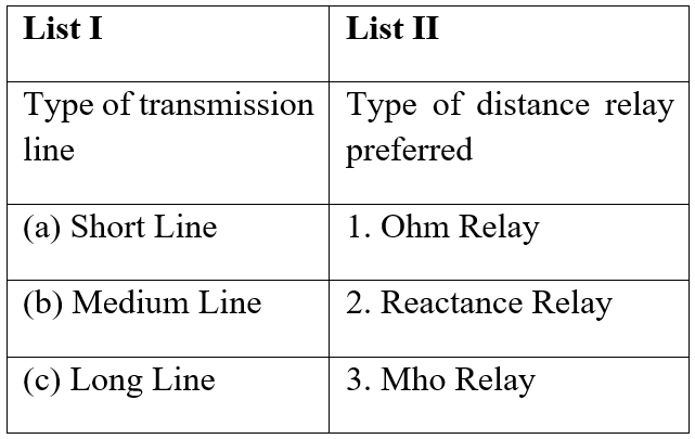
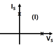
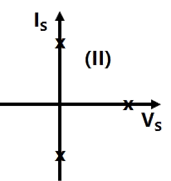
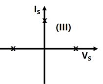
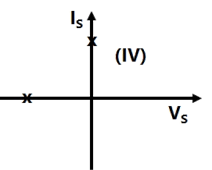
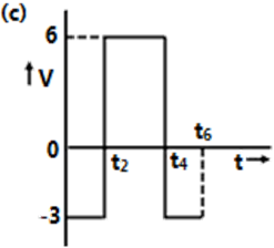
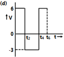
Sign in to UnlockThe following circuit has a source voltage Vs as shown in the graph. The current through the circuit is also shown.
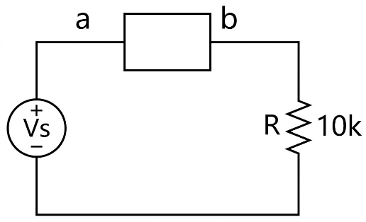
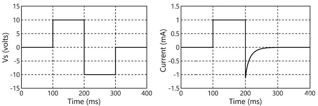
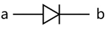
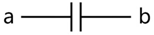
The element connected between a and b could be
Explanation Locked!
Unlock this branch to view the explanation, track, bookmark and more.
Sign in to UnlockThe increasing order of speed of data access for the following devices is
(i) Cache Memory
(ii) CDROM
(iii) Dynamic RAM
(iv) Processor Registers
(v) Magnetic Tape
Explanation Locked!
Unlock this branch to view the explanation, track, bookmark and more.
Sign in to UnlockAssume for simplicity that N people, all born in April (a month of 30 days), are collected in a room. Consider the event of at least two people in the room being born on the same date of the month, even if in different years. e.g. 1980 and 1985. What is the smallest N so that the probability of this event exceeds 0.5 ?
Explanation Locked!
Unlock this branch to view the explanation, track, bookmark and more.
Sign in to UnlockLet . The iterative steps for the solution using Newton-Raphson's method is given by


Explanation Locked!
Unlock this branch to view the explanation, track, bookmark and more.
Sign in to UnlockThe measurement system shown in the figure uses three sub-systems in cascade whose gains are specified as and . The relative small errors associated with each respective subsystem as and are and . The error associated with the output is:


Explanation Locked!
Unlock this branch to view the explanation, track, bookmark and more.
Sign in to UnlockOut of the following plant categories
(i) Nuclear
(ii) Run-of-river
(iii) Pump Storage
(iv) Diesel
The base load power plants are
Explanation Locked!
Unlock this branch to view the explanation, track, bookmark and more.
Sign in to UnlockThe complete set of only those Logic Gates designated as Universal Gates is
Explanation Locked!
Unlock this branch to view the explanation, track, bookmark and more.
Sign in to Unlockf (x, y) is a continuous function defined over. Given the two constraintsand , the volume under f(x, y) is


Explanation Locked!
Unlock this branch to view the explanation, track, bookmark and more.
Sign in to UnlockA Linear Time Invariant system with an impulse response h(t) produces output y(t) when input x(t) is applied. When the input is applied to a system with impulse response , the output will be


Explanation Locked!
Unlock this branch to view the explanation, track, bookmark and more.
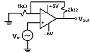
Sign in to UnlockThe nature of feedback in the op-amp circuit shown is
Explanation Locked!
Unlock this branch to view the explanation, track, bookmark and more.
Sign in to UnlockThe z-transform of a signal x[n] is given by. It is applied to a system, with a transfer function. Let the output be y(n). Which of the following is true?


y(n) is non casual with finite support
y(n) is casual with infinite support

;;


Explanation Locked!
Unlock this branch to view the explanation, track, bookmark and more.
Sign in to UnlockA cubic polynomial with real coefficients
Explanation Locked!
Unlock this branch to view the explanation, track, bookmark and more.
Sign in to UnlockThe Fourier Series coefficients, of a periodic signal x(t), expressed as are given by ; ; ; ; ; and for . Which of the following is true?


Explanation Locked!
Unlock this branch to view the explanation, track, bookmark and more.
Sign in to UnlockA cascade of 3 Linear Time Invariant systems is causal and unstable. From this, we conclude that
Explanation Locked!
Unlock this branch to view the explanation, track, bookmark and more.
Sign in to UnlockFor the circuit shown, find out the current flowing through the 2Ω resistance. Also identify the changes to be made to double the current through the 2Ω resistance.
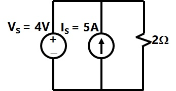
(5A; Put = 20V)

(2A; Put = 8V)
(5A; Put = 10V)
(7A; Put = 12V)
Explanation Locked!
Unlock this branch to view the explanation, track, bookmark and more.
Sign in to UnlockIt's line integral over the straight line from evaluates to


Explanation Locked!
Unlock this branch to view the explanation, track, bookmark and more.
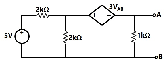
Sign in to UnlockFor the circuit given, the Thevenin's resistance across the terminals A and B is
Explanation Locked!
Unlock this branch to view the explanation, track, bookmark and more.
Sign in to UnlockFor the circuit given, the Thevenin's voltage across the terminals A and B is
Explanation Locked!
Unlock this branch to view the explanation, track, bookmark and more.
Sign in to UnlockThe two inputs of a CRO are fed with two stationary periodic signals. In the X-Y mode, the screen shows a figure which changes from ellipse to circle and back to ellipse with its major axis changing orientation slowly and repeatedly. The following inference can be made from this.
Explanation Locked!
Unlock this branch to view the explanation, track, bookmark and more.
Sign in to UnlockFor the Y-bus matrix of a 4-bus system given in per unit, the buses having shunt elements are

Explanation Locked!
Unlock this branch to view the explanation, track, bookmark and more.
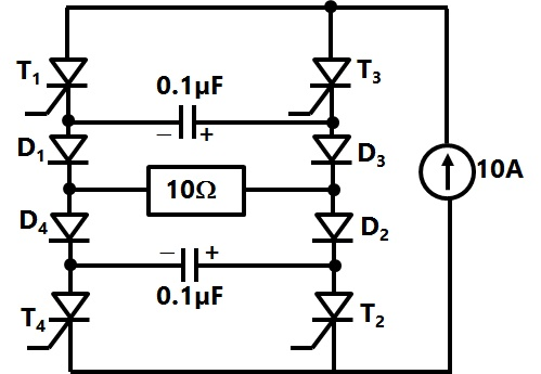
Sign in to UnlockThe Current Source Inverter shown in figure is operated by alternately turning on thyristor pairs and . If the load is purely resistive, the theoretical maximum output frequency obtainable will be


Explanation Locked!
Unlock this branch to view the explanation, track, bookmark and more.
Sign in to UnlockThe first two rows of Routh's tabulation of a third order equation are as follows.
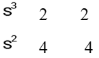
The means there are
Explanation Locked!
Unlock this branch to view the explanation, track, bookmark and more.
Sign in to UnlockA system is described by the following state and output equations


Where u(t) is the input and y(t) is the output.
The system transfer function is


Explanation Locked!
Unlock this branch to view the explanation, track, bookmark and more.
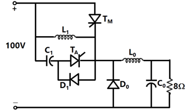
Sign in to UnlockIn the chopper circuit shown, the main thyristor is operated at a duty ratio of 0.8 which is much larger the commutation interval. If the maximum allowable reapplied dv/dt on is , what should be the theoretical minimum value of ? Assume current ripple through to be negligible.


Explanation Locked!
Unlock this branch to view the explanation, track, bookmark and more.
Sign in to UnlockA 500 MW, 21 kV, 50 Hz, 3-phase, 2-pole synchronous generator having a rated p.f = 0.9, has a moment of inertia of . The inertia constant (H) will be

Explanation Locked!
Unlock this branch to view the explanation, track, bookmark and more.
Sign in to UnlockA system is described by the following state and output equations
Where u(t) is the input and y(t) is the output.
The state-transition matrix of the above system is


Explanation Locked!
Unlock this branch to view the explanation, track, bookmark and more.
Sign in to UnlockIn an 8085 microprocessor, the contents of the Accumulator, after the following instructions are executed will become
XRA A
MVI B F0H
SUB B
Explanation Locked!
Unlock this branch to view the explanation, track, bookmark and more.
Sign in to UnlockThe polar plot of an open loop stable system is shown below. The closed loop system is
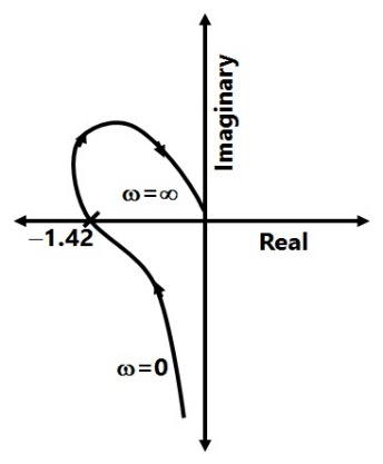
Explanation Locked!
Unlock this branch to view the explanation, track, bookmark and more.
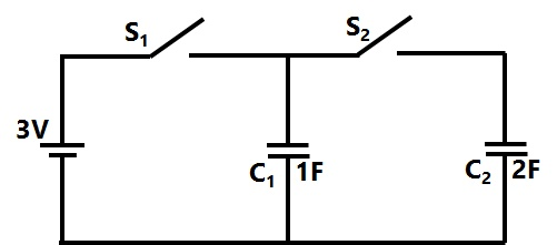
Sign in to UnlockIn the figure shown, all elements used are ideal. For time t < 0, \(S_1\) remained closed and \(S_2\) open. At
t = 0, \(S_1\) is opened and \(S_2\) is closed. If the voltage \(Vc_2\) across the capacitor \(C_2\) at t = 0 is zero, the voltage across the capacitor combination at will be

Explanation Locked!
Unlock this branch to view the explanation, track, bookmark and more.
Sign in to UnlockTransformer and emitter follower can both be used for impedance matching at the output of an audio amplifier. The basic relationship between the input power and output power in both the cases is


for both transformer and emitter follower

for both transformer and emitter follower

for transformer and for emitter follower

for transformer for emitter follower
Explanation Locked!
Unlock this branch to view the explanation, track, bookmark and more.
Sign in to UnlockThe asymptotic approximation of the log-magnitude v/s frequency plot of a system containing only real poles and zeros is shown. Its transfer function is
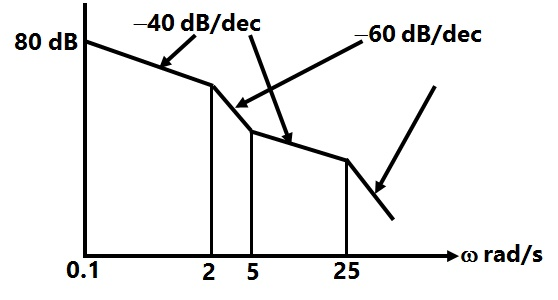


Explanation Locked!
Unlock this branch to view the explanation, track, bookmark and more.
Sign in to UnlockThe open loop transfer function of a unity feedback system is given by . The gain margin of this system is

Explanation Locked!
Unlock this branch to view the explanation, track, bookmark and more.
Sign in to UnlockThe trace and determinant of a 2 × 2 matrix are known to be -2 and -35 respectively. Its Eigen values are
Explanation Locked!
Unlock this branch to view the explanation, track, bookmark and more.
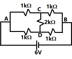
Sign in to UnlockThe current through the 2kΩ resistance in the circuit shown is
Explanation Locked!
Unlock this branch to view the explanation, track, bookmark and more.
Sign in to UnlockHow many 200W/220V incandescent lamps connected in series would consume the same total power as a single 100W/220V incandescent lamp?
Explanation Locked!
Unlock this branch to view the explanation, track, bookmark and more.
Sign in to UnlockMatch the items in List-I with the items in List-II and select the correct answer using the codes given below the lists
Explanation Locked!
Unlock this branch to view the explanation, track, bookmark and more.
Sign in to UnlockAn SCR is considered to be a semi-controlled device because
Explanation Locked!
Unlock this branch to view the explanation, track, bookmark and more.
Sign in to UnlockMatch the switch arrangements on the top row to the steady-state V-I characteristics on the lower row. The steady state operating points are shown by large black dots.


Explanation Locked!
Unlock this branch to view the explanation, track, bookmark and more.
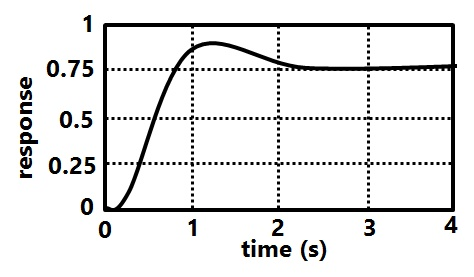
Sign in to UnlockThe unit-step response of a unity feedback system with open loop transfer function is shown in the figure. The value of K is

Explanation Locked!
Unlock this branch to view the explanation, track, bookmark and more.
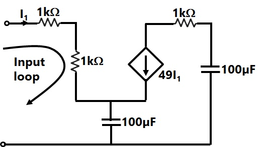
Sign in to UnlockThe equivalent capacitance of the input loop of the circuit shown is
Explanation Locked!
Unlock this branch to view the explanation, track, bookmark and more.
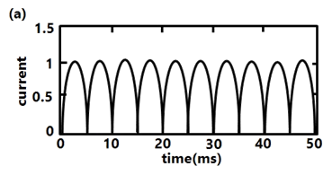
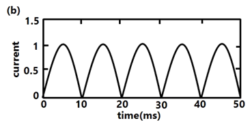
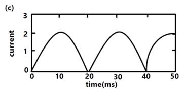
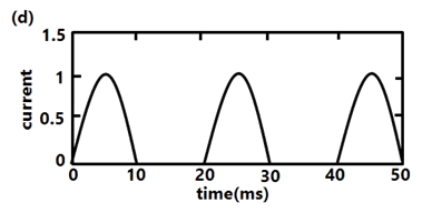
Sign in to UnlockThe circuit shows an ideal diode connected to a pure inductor and is connected to a purely sinusoidal 50Hz voltage source. Under Ideal conditions the current waveform through the inductor will look like

Explanation Locked!
Unlock this branch to view the explanation, track, bookmark and more.
Sign in to UnlockThe pressure coil of a dynamometer type wattmeter is
Explanation Locked!
Unlock this branch to view the explanation, track, bookmark and more.
Sign in to UnlockThe following circuit has R = 10kΩ, C = 10µF. The input voltage is a sinusoid at 50Hz with an RMS value of 10V. Under ideal conditions, the current from the source is

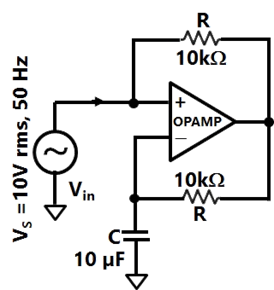
leading by 90°

leading by 90°

10mA leading by 90°
leading by 90°
Explanation Locked!
Unlock this branch to view the explanation, track, bookmark and more.
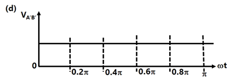
Sign in to UnlockFigure shows the extended view of a 2 pole dc machine with 10 armature conductors. Normal brush positions are shown by A and B, placed at the inter-polar axis. If the brushes are now shifted, in the direction of rotation, to A' and B' as shown, the voltage waveform will resemble

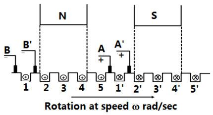
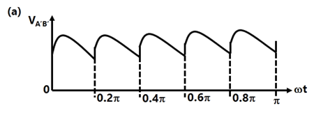
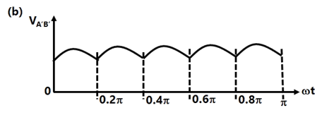
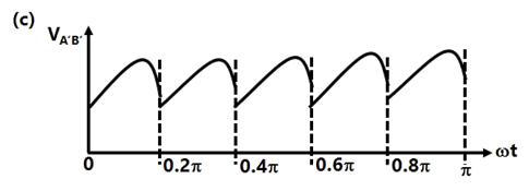
Explanation Locked!
Unlock this branch to view the explanation, track, bookmark and more.
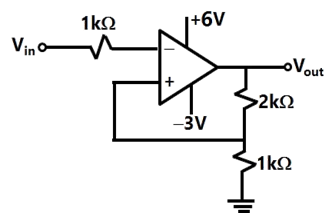
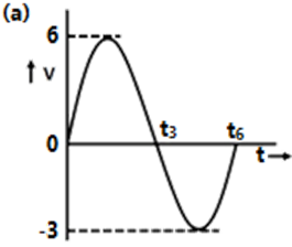
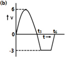
Sign in to UnlockAn ideal op-amp circuit and its input waveform are shown in the figures. The output waveform of this circuit will be
Explanation Locked!
Unlock this branch to view the explanation, track, bookmark and more.
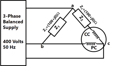
Sign in to UnlockThe figure shows a three-phase delta connected load supplied from a 400V, 50 Hz, 3-phase balanced source. The pressure coil (PC) and current coil (CC) of a wattmeter are connected to the load as shown, with the coil polarities suitably selected to ensure a positive deflection. The wattmeter reading will be
Explanation Locked!
Unlock this branch to view the explanation, track, bookmark and more.
Sign in to UnlockA field excitation of 20 A in a certain alternator results in an armature current of 400 A in short Circuit and a terminal voltage of 2000 V on open circuit. The magnitude of the internal voltage drop within the machine at a load current of 200 A is
Explanation Locked!
Unlock this branch to view the explanation, track, bookmark and more.
Sign in to UnlockThe single phase, 50Hz, iron core transformer in the circuit has both the vertical arms of cross sectional area and both the horizontal arms of cross sectional area . If the two windings shown were wound instead on opposite horizontal arms, the mutual inductances will


Explanation Locked!
Unlock this branch to view the explanation, track, bookmark and more.
Sign in to Unlock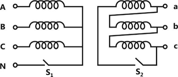
With both S1 and S2 open, the core flux waveform will be
Explanation Locked!
Unlock this branch to view the explanation, track, bookmark and more.
Sign in to UnlockWith S2 closed and S1 open, the current waveform in the delta winding will be
Explanation Locked!
Unlock this branch to view the explanation, track, bookmark and more.
Sign in to Unlock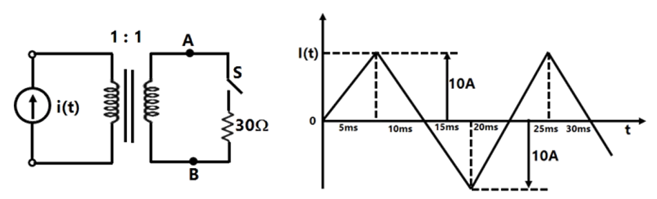
The circuit diagram shows a two-winding, loss less transformer with no leakage flux, excited from a current source, i(t), whose waveform is also shown. The transformer has a magnetizing inductance of 400/π mH.
The peak voltage across A and B, with S open is
Explanation Locked!
Unlock this branch to view the explanation, track, bookmark and more.
Sign in to UnlockThe circuit diagram shows a two-winding, loss less transformer with no leakage flux, excited from a current source, i(t), whose waveform is also shown. The transformer has a magnetizing inductance of 400/π mH.
If the waveform of i(t) is changed to , the peak voltage across A and B with S closed is

Explanation Locked!
Unlock this branch to view the explanation, track, bookmark and more.
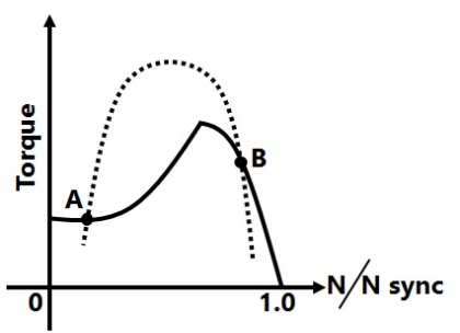
Sign in to UnlockA 3-phase squirrel cage induction motor supplied from a balanced 3-phase source drives a mechanical load. The torque-speed characteristics of the motor (solid curve) and of the load (dotted curve) are shown. Of the two equilibrium points A and B. which of the following options correctly describes the stability of A and B?
Explanation Locked!
Unlock this branch to view the explanation, track, bookmark and more.
Sign in to UnlockThe figure below shows coils 1 and 2, with dot markings as shown, having 4000 and 6000 turns respectively. Both the coils have a rated current of 25 A. Coil 1 is excited with single phase, 400 V, 50 Hz supply.
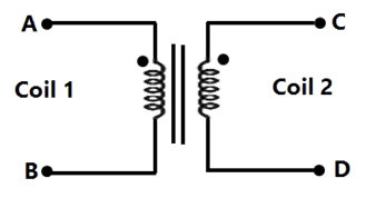
The coils are to be connected to obtain a single phase, 400/1000 V, auto-transformer to drive a load of 10kVA. Which of the options given should be exercised to realize the required auto-transformer?
Explanation Locked!
Unlock this branch to view the explanation, track, bookmark and more.
Sign in to UnlockThe figure below shows coils 1 and 2, with dot markings as shown, having 4000 and 6000 turns respectively. Both the coils have a rated current of 25 A. Coil 1 is excited with single phase, 400 V, 50 Hz supply.
In the autotransformer obtained in Question 57, the current in each coil is
Explanation Locked!
Unlock this branch to view the explanation, track, bookmark and more.
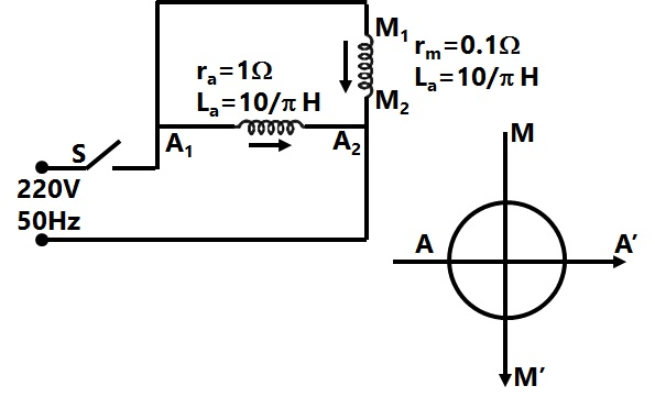
Sign in to UnlockA 220V, 50 Hz, single-phase induction motor has the following connection diagram and winding orientations shown. MM’ is the axis of the main stator winding and AA' is that of the auxiliary winding . Directions of the winding axes indicate direction of .flux when currents in the windings are in the directions shown. Parameters of each winding are indicated. When switch S is closed, the motor.


Explanation Locked!
Unlock this branch to view the explanation, track, bookmark and more.
Sign in to UnlockFor a fixed value of complex power flow in a transmission line having a sending end voltage V, the real power loss will be proportional to
V


Explanation Locked!
Unlock this branch to view the explanation, track, bookmark and more.
Sign in to UnlockMatch the items in List-I with the items in List-II and select the correct answer using the codes given below the lists.
List I | List II |
To | Use |
a. Improve power factor | 1. shunt reactor |
b. Reduce the current ripples | 2. shunt capacitor |
c. Increase the power flow in line | 3. series capacitor |
d. Reduce the Ferranti effect | 4. series reactor |
Explanation Locked!
Unlock this branch to view the explanation, track, bookmark and more.
Sign in to UnlockThree generators are feeding a load of 100 MW. The details of the generators are
Rating (MW) | Efficiency (%) | Regulation (p.u.) on 100 MAVA base | |
Generator-1 | 100 | 20 | 0.02 |
Generator-2 | 100 | 30 | 0.04 |
Generator-3 | 100 | 40 | 0.03 |
In the event of increased load power demand, which of the following will happen?
Explanation Locked!
Unlock this branch to view the explanation, track, bookmark and more.
Sign in to Unlock