
Base load power plants are
P : wind farms
Q : run-of-river plants
R : nuclear power plants
S : diesel power plants
Explanation Locked!
Unlock this branch to view the explanation, track, bookmark and more.
Sign in to UnlockA solution of the ordinary differential equation is such that y(0) = 2 and . The value of is ________.


Explanation Locked!
Unlock this branch to view the explanation, track, bookmark and more.
Sign in to UnlockConsider the economic dispatch problem for power plant having two generating units. The fuel costs in Rs/MWh along with the generation limits for the two units are given below.


The incremental cost (in Rs/MWh) of the power plant when it supplies 200 MW is ___________.
Explanation Locked!
Unlock this branch to view the explanation, track, bookmark and more.
Sign in to UnlockIn a linear two-port network, when 10V is applied to port 1, a current of 4A flows through port 2 when it is short – circuited. When 5V is applied to port 1, a current of 1.25A flows through a resistance connected across port 2. When 3 V is applied to port 1, the current (in Ampere) through a resistance connected across port 2 is_______________.


Explanation Locked!
Unlock this branch to view the explanation, track, bookmark and more.
Sign in to UnlockThe open loop poles of a third order unity feedback system are at 0, -1, -2. Let the frequency corresponding to the point where the root locus of the system transit to unstable region be K. Now suppose we introduce a zero in the open loop transfer function at -3, while keeping all the earlier open loop poles intact. Which one of the following is TRUE about the point where the root locus of the modified system transits to unstable region?
Explanation Locked!
Unlock this branch to view the explanation, track, bookmark and more.
Sign in to UnlockConsider a discrete time signal given by

The region of convergence of its Z – transform would be
Explanation Locked!
Unlock this branch to view the explanation, track, bookmark and more.
Sign in to UnlockA random variable X has probability density function f(x) as given below:

If the expected value , then Pr[X < 0.5] is___________.

Explanation Locked!
Unlock this branch to view the explanation, track, bookmark and more.
Sign in to UnlockA moving average function is given by . If the input u is a sinusoidal signal of frequency, then in steady state, the output y will lag u (in degree) by___________.


Explanation Locked!
Unlock this branch to view the explanation, track, bookmark and more.
Sign in to UnlockTwo players, A and B, alternately keep rolling a fair dice. The person to get a six first wins the game. Given that player A starts the game, the probability that A wins the game is
Explanation Locked!
Unlock this branch to view the explanation, track, bookmark and more.
Sign in to UnlockThe signum function is given by

The Fourier series expansion of sgn has

Explanation Locked!
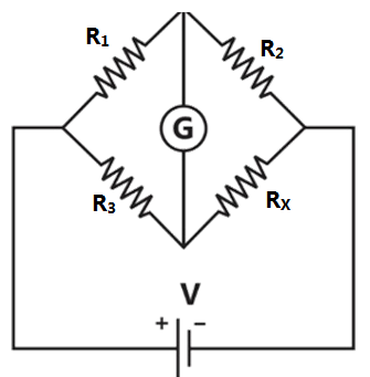
Unlock this branch to view the explanation, track, bookmark and more.
Sign in to UnlockWhen the Wheatstone bridge shown in the figure is used to find the value of resistor , the galvanometer G indicates zero current when and . If is known with ± 5% tolerance on its nominal value of 100 Ω, what is the range of in ohms ?


Explanation Locked!
Unlock this branch to view the explanation, track, bookmark and more.
Sign in to UnlockAn unbalanced DC Wheatstone bridge is shown in the figure. At what value of p will the magnitude of be maximum?

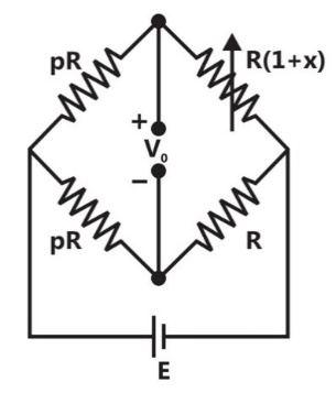

(1 + x)


Explanation Locked!
Unlock this branch to view the explanation, track, bookmark and more.
Sign in to UnlockAn 8-bit, unipolar successive approximation register type ADC is used to convert 3.5V to digital equivalent output. The reference voltage is +5V. The output of the ADC, at the end of 3rd clock pulse after the start of conversion, is
Explanation Locked!
Unlock this branch to view the explanation, track, bookmark and more.
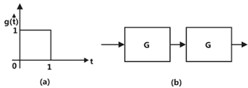
Sign in to UnlockThe impulse response g(t) of a system, G, is as shown in figure (a). What is the maximum value attained by the impulse response of two cascaded blocks of G as shown in figure (b)?


1
Explanation Locked!
Unlock this branch to view the explanation, track, bookmark and more.
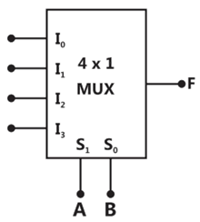
Sign in to UnlockIn the 4 x 1 multiplexer, the output F is given by. Find the required input .


Explanation Locked!
Unlock this branch to view the explanation, track, bookmark and more.
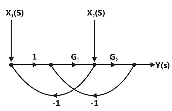
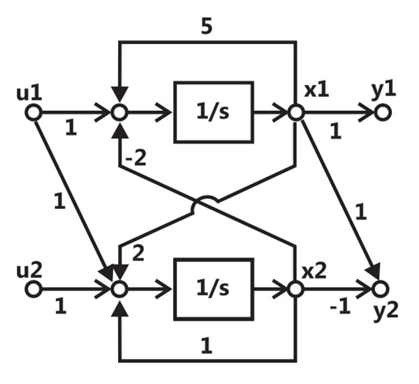
Sign in to UnlockFor the signal – flow graph shown in the figure, which one of the following expressions is equal to the transfer function


Explanation Locked!
Unlock this branch to view the explanation, track, bookmark and more.
Sign in to Unlock(0,1,3,4,5,7,9,11,12,13,14,15) is a maxterm representation of a Boolean function f(A,B,C,D) where A is the MSB and D is the LSB. The equivalent minimized representation of this function is


Explanation Locked!
Unlock this branch to view the explanation, track, bookmark and more.
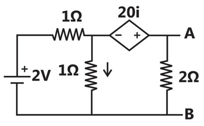
Sign in to UnlockFor the given circuit, the Thevenin equivalent is to be determined. The Thevenin voltage,

(in Volt), seen from terminal AB is _____________.
Explanation Locked!
Unlock this branch to view the explanation, track, bookmark and more.
Sign in to UnlockFind the transfer function of the system given below.


Explanation Locked!
Unlock this branch to view the explanation, track, bookmark and more.
Sign in to UnlockDetermine the correctness or otherwise of the followings Assertion [a] and Reason [r]
Assertion: Fast decoupled load flow method. Gives approximate load flow solution because it uses several assumptions.
Reason: Accuracy depends on the power mismatch vector tolerance.
Explanation Locked!
Unlock this branch to view the explanation, track, bookmark and more.
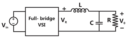
Sign in to UnlockThe single-phase full-bridge voltage inverter (VSI), shown in figure, has an output frequency of 50 Hz. It uses unipolar pulse width modulation with switching frequency of 50 kHz and modulation index of 0.7. For , L = 9.55 mH, C = 63.66 , R = 5Ω, the amplitude of the fundamental component in the output voltage (in Volt) under steady-state is __________________.


Explanation Locked!
Unlock this branch to view the explanation, track, bookmark and more.
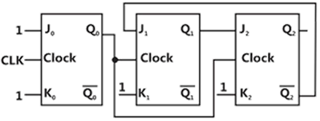
Sign in to UnlockThe figure shows a digital circuit constructed using negative edge triggered J – K flip flops. Assume a starting state of . This state will repeat after __________ number cycles of the clock CLK.

Explanation Locked!
Unlock this branch to view the explanation, track, bookmark and more.
Sign in to UnlockConsider a one – turn rectangular loop of wire placed in a uniform magnetic field as shown in the figure. The plane of the loop is perpendicular to the field lines. The resistance of the loop is and its inductance is negligible. The magnetic flux density (in Tesla) is a function of time, and is given by B(t) =0.25sin , where radian/second. The power absorbed (in Watt) by the loop from the magnetic field is


Explanation Locked!
Unlock this branch to view the explanation, track, bookmark and more.
Sign in to UnlockA 50 Hz generating unit has H-constant of 2 MJ/MVA. The machine is initially operating in steady state at synchronous speed, and producing 1 pu of real power. The initial value of the rotor angle is 5º, when a bolted there phase to ground short circuit fault occurs terminal of the generator. Assuming the input mechanical power to remain at 1 pu, the value of in degrees, 0.02 second after the fault is ____________.

Explanation Locked!
Unlock this branch to view the explanation, track, bookmark and more.
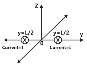
Sign in to UnlockA steady current I is flowing in the –x direction through each two infinitely long wires at as shown in the figure. The permeability of the medium is. The -field at (0, L, 0) is


0

Explanation Locked!
Unlock this branch to view the explanation, track, bookmark and more.
Sign in to UnlockIf a continuous function f(x) does not have a root in the interval [a, b], then which one of the following statement is TRUE?
f(a) . f(b) = 0
f(a) . f(b) < 0
f(a) . f(b) > 0
f(a)/f(b)

Explanation Locked!
Unlock this branch to view the explanation, track, bookmark and more.
Sign in to UnlockConsider a function , where r is the distance from the origin and is the unit vector is the radial direction, the divergence of this function over a sphere of radius R, which includes the origin, is


0


Explanation Locked!
Unlock this branch to view the explanation, track, bookmark and more.
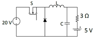
Sign in to UnlockIn the following chopper, the duty ratio of switch S is 0.4. If the inductor and capacitor are sufficiently large to ensure continuous inductor current and ripple free capacitor voltage, the charging current (in Ampere) of the 5 V battery, under steady-state, is _____________.
Explanation Locked!
Unlock this branch to view the explanation, track, bookmark and more.
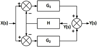
Sign in to UnlockIn the signal flow diagram given in the figure, are possible inputs whereas are possible outputs. When would the SISO system derived from this diagram be controllable and observable?


When is the only input and is the only output.


When is the only input and is the only output.

When is the only input and is the only output.

When is the only input and is the only output.
Explanation Locked!
Unlock this branch to view the explanation, track, bookmark and more.
Sign in to UnlockThe circuit shown is meant to supply a resistive load from separate DC voltage sources. The switches S1 and S2 are controlled so that only one of them is ON at any instant. S1 is turned on for 0.2 ms and S2 is turned on for 0.3 ms in a 0.5 ms switching cycle time period. Assuming continuous conduction of the inductor current and negligible ripple on the capacitor voltage, the outputs voltage (in Volt) across is _____.


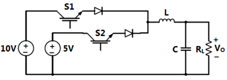
Explanation Locked!
Unlock this branch to view the explanation, track, bookmark and more.
Sign in to UnlockIn the given circuit, the silicon transistor has and a collector voltage . Then the ratio of and is ____________.


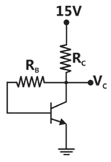
Explanation Locked!
Unlock this branch to view the explanation, track, bookmark and more.
Sign in to UnlockA self-commutating switch SW, operated at duty cycle is used to control the load voltage as shown in the figure. Under steady state operating conditions, the average voltage across the inductor and the capacitor respectively, are

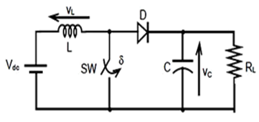
and


and

and

and
Explanation Locked!
Unlock this branch to view the explanation, track, bookmark and more.
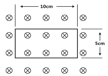
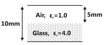
Sign in to UnlockA parallel plate capacitor is partially filled with glass of dielectric constant 4.0 as shown below. The dielectric strength of air and glass are 30kV/cm and 300kV/cm, respectively. The maximum voltage (in kilovolts) which can be applied across the capacitor without any breakdown is _____________.
Explanation Locked!
Unlock this branch to view the explanation, track, bookmark and more.
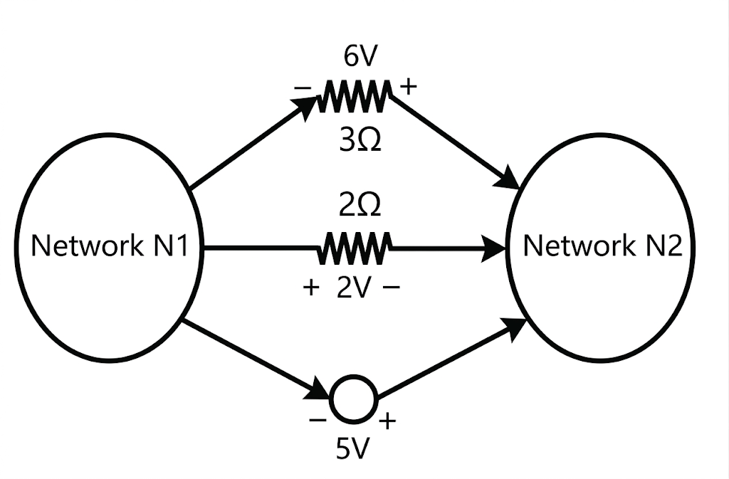
Sign in to UnlockThe voltages developed across the and resistors shown in the figure are 6V and 2V respectively, with the polarity as marked. What is the power (in Watt) delivered by the 5V voltage source?


Explanation Locked!
Unlock this branch to view the explanation, track, bookmark and more.
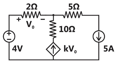
Sign in to UnlockIn the given circuit, the parameter k is positive, and the power dissipated in the 2 resistor is 12.5W. The value of k is ____________.

Explanation Locked!
Unlock this branch to view the explanation, track, bookmark and more.
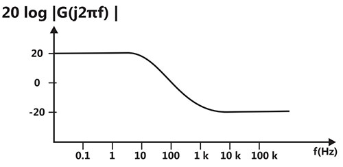
Sign in to UnlockA Bode magnitude plot for the transfer function G(s) of a plant is shown in the figure. Which one of the following transfer functions best describes the plant?


Explanation Locked!
Unlock this branch to view the explanation, track, bookmark and more.
Sign in to UnlockIf the sum of the diagonal elements of a 2 x 2 matrix is -6, then the maximum possible value of determinant of the matrix is ____________.
Explanation Locked!
Unlock this branch to view the explanation, track, bookmark and more.
Sign in to UnlockThe transfer function of a second order real system with a perfectly flat magnitude response of unity has a pole at
(2 – j3). List all the poles and zeroes.
Explanation Locked!
Unlock this branch to view the explanation, track, bookmark and more.
Sign in to UnlockThe maximum value of ‘a’ such that the matrix has three linearly independent real eigenvectors is


Explanation Locked!
Unlock this branch to view the explanation, track, bookmark and more.
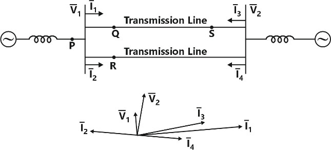
Sign in to UnlockA sustained three-phase fault occurs in the power system shown in the figure. The current and voltage phasors during the fault (on a common reference), after the natural transients have died down are also shown. Where is the fault located?
Explanation Locked!
Unlock this branch to view the explanation, track, bookmark and more.
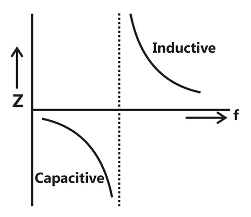
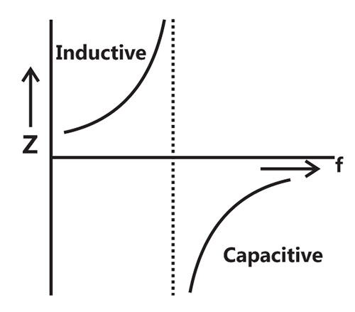
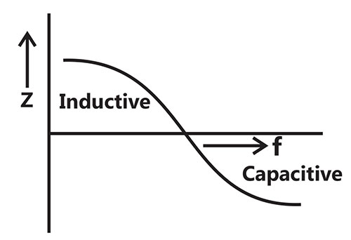
Sign in to UnlockAn inductor is connected in parallel with a capacitor as shown in the figure.
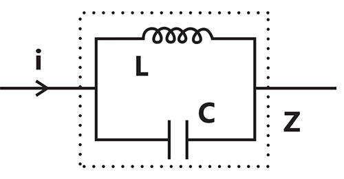
As the frequency of current i is increased, the impedance (Z) of the network varies as
Explanation Locked!
Unlock this branch to view the explanation, track, bookmark and more.
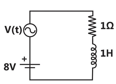
Sign in to UnlockThe circuit shown in the figure has two sources connected in series. The instantaneous voltage of the AC source (in Volt) is given by . If the circuit is in steady state, then the RMS value of the current (in Ampere) flowing in the circuit is

Explanation Locked!
Unlock this branch to view the explanation, track, bookmark and more.
Sign in to UnlockA separately excited DC generator has an armature resistance of 0.1Ω and negligible armature inductance. At rated field current and rated rotor speed, its open–circuit voltage is 200 V. When this generator is operated at half the rated speed, with half the rated field current, an un-charged 1000 μF capacitor is suddenly connected across the armature terminals. Assume that the speed remains unchanged during the transient. At what time (in microsecond) after the capacitor is connected will the voltages across it reach 25 V?
Explanation Locked!
Unlock this branch to view the explanation, track, bookmark and more.
Sign in to UnlockOf the four characteristics given below, which are the major requirements for an instrumentation amplifier?
P. High common mode rejection ratio
Q. High input impedance.
R. High linearity.
S. High output impedance.
Explanation Locked!
Unlock this branch to view the explanation, track, bookmark and more.
Sign in to UnlockA separately excited DC motor runs at 1000 rpm on no load when its armature terminals are connected to a 200V DC source and the rated voltage is applied to the field winding. The armature resistance of this motor is 1Ω. The no-load armature current is negligible. With the motor developing its full load torque, the armature voltage is set so that the rotor speed is 500 rpm. When the load torque is reduced to 50% of the full load value under the same armature voltage conditions, the speed rises to 520 rpm. Neglecting the rotational losses, the full load armature current (in Ampere) is ________________.
Explanation Locked!
Unlock this branch to view the explanation, track, bookmark and more.
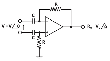
Sign in to UnlockConsider the circuit shown in the figure. In this circuit and . The input voltage is sinusoidal with a frequency of 50Hz, represented as a phasor with magnitude and phase angle 0 radian as shown in the figure. The output voltage is represented as a phasor with magnitude and phase angle radian. What is the value of the output phase angle (in radian) relative to the phase angle of the input voltage?


0


Explanation Locked!
Unlock this branch to view the explanation, track, bookmark and more.
Sign in to UnlockA DC motor has the following specifications: 10 hp, 37.5A, 230 V; flux/pole = 0.01 Wb, number of poles = 4, number of conductors = 666, number of parallel paths = 2. Armature resistance = 0.267 Ω. The armature reaction is negligible and rotational losses are 600 W. the motor operates from a 230 V DC supply. If the motor runs at 1000 rpm, the output torque produced (in Nm) is ____________.
Explanation Locked!
Unlock this branch to view the explanation, track, bookmark and more.
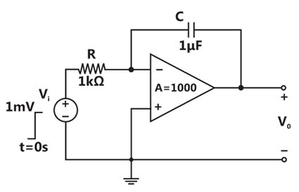
Sign in to UnlockThe op – amp shown in the figure has a finite gain A = 1000 and an infinite input resistance. A step voltage is applied at the input at time t=0 as shown. Assuming that the operational amplifier is not saturated, the time constant (in millisecond) of the output voltage is

Explanation Locked!
Unlock this branch to view the explanation, track, bookmark and more.
Sign in to UnlockA (0-50A) moving coil ammeter has a voltage drop of 0.1 V across its terminals at full scale deflection. The external shunt resistance (in milliohms) needed to extend its range to (0 – 500A) is ____________.
Explanation Locked!
Unlock this branch to view the explanation, track, bookmark and more.
Sign in to UnlockThe self-inductance of the primary winding of a single phase, 50 Hz, transformer is 800 mH, and that of the secondary winding is 600 mH. The mutual inductance between these two windings is 480 mH. The secondary winding of this transformer is short circuited and the primary winding is connected to a 50 Hz, single phase, sinusoidal voltage source. The current flowing in both the windings is less than their respective rated currents. The resistance of both windings can be neglected. In this condition, what is the effective inductance (in mH) seen by the source?
Explanation Locked!
Unlock this branch to view the explanation, track, bookmark and more.
Sign in to UnlockThe primary mmf is least affected by the secondary terminal conditions in a
Explanation Locked!
Unlock this branch to view the explanation, track, bookmark and more.
Sign in to UnlockA 3 – phase 50 Hz square wave (6-step) VSI feeds a 3 – phase, 4 pole induction motor. The VSI line voltage has a dominant harmonic component. If the operating slip of the motor with respect to fundamental component voltages is 0.04, the slip of the motor with respect to harmonic component of voltage is __________________.

Explanation Locked!
Unlock this branch to view the explanation, track, bookmark and more.
Sign in to UnlockA 200/400V, 50 Hz, two-winding transformer is rated at 20 kVA. Its windings are connected as an auto-transformer of rating 200/600 V. A resistive load of 12 Ω is connected to the high voltage (600V) side of the auto-transformer. The value of equivalent load resistance (in Ohm) as seen from low voltage side is _____________.
Explanation Locked!
Unlock this branch to view the explanation, track, bookmark and more.
Sign in to UnlockTwo single-phase transformers and each rated at 500 kVA are operated in parallel. Percentage impedances of and are (1 + j6) and (0.8 + j4.8), respectively. To share a load of 1000 kVA at 0.8 lagging power factor, the contribution of (in kVA) is ______________


Explanation Locked!
Unlock this branch to view the explanation, track, bookmark and more.
Sign in to UnlockConsider a HVDC link which uses thyristor based line- commutated converter as shown in the figure. For a power flow of 750 MW from system 1 to system 2, the voltages at the two ends, and the current are given by: =500 kV, and I=1.5 kA. If the direction of power flow is to be reversed (that is from system 2 to system 1) without changing the electrical connections, then which one of the following combinations is feasible?


and I = 1.5 kA

and I =1.5 kA

and I = – 1.5kA

and I = – 1.5 kA
Explanation Locked!
Unlock this branch to view the explanation, track, bookmark and more.
Sign in to Unlock