
Login to track your progress, bookmark questions, and view history.
Q#1
Chopper
GATE EE 2015
NAT
+2 marks
-0 marks
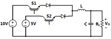
The circuit shown is meant to supply a resistive load from separate DC voltage sources. The switches S1 and S2 are controlled so that only one of them is ON at any instant. S1 is turned on for 0.2 ms and S2 is turned on for 0.3 ms in a 0.5 ms switching cycle time period. Assuming continuous conduction of the inductor current and negligible ripple on the capacitor voltage, the outputs voltage (in Volt) across is _____.


Sign in to see the solution
Log in to view the explanation, track your attempts, and keep your progress.
Sign in to Unlock
Login to keep track of your progress with the tool with daily goals, questions preparation and more.
Browse Practice Questions by Chapters / Topics in Browse Practice Questions by Chapters / Topics in GATE Electrical Engineering
Total Questions
Attempted
% Attempted
Correct
% Correct
Login to keep track of your progress with the tool with daily goals, questions preparation and more.
| Topic | Questions | Attempted | Correct | |
|---|---|---|---|---|
| Network Analysis | 268 | 0 | 0 | |
| Signals and Systems | 168 | 0 | 0 | |
| Control Systems | 262 | 0 | 0 | |
| Analog Electronics | 186 | 0 | 0 | |
| Digital Electronics | 150 | 0 | 0 | |
| Electrical Machines | 399 | 0 | 0 | |
| Power Electronics | 243 | 0 | 0 | |
| Power Systems | 350 | 0 | 0 | |
| EMFT EE | 111 | 0 | 0 | |
| Measurement | 160 | 0 | 0 | |
| Engineering Mathematics | 236 | 0 | 0 | |
| General Aptitude | 221 | 0 | 0 |
Transformers
112 Qs
0 Att
0 Cor
Construction of Transformer
Induced EMF - Transformer
Equivalent Circuit - Transformer
Testing of a Transformer
Losses and Efficiency - Transformer
Voltage Regulation - Transformer
Three Phase Transformer
Auto Transformer
Parallel Operation - Transformer
Harmonics in Transformer
DC Machines
81 Qs
0 Att
0 Cor
Construction of DC Machines
EMF and Torque Equation
Equivalent Circuit - DC Machines
Losses and Efficiency - DC Machines
Speed Control of DC Motor
Starting, Braking and Testing of DC Motor
Characteristics of DC machines
Electromechanical Energy Conversion
Synchronous Machines
84 Qs
0 Att
0 Cor
Induced EMF - Synchronous Machines
Voltage Regulation Methods
Equivalent Circuit - Synchronous Machines
Synchronous Impedance
Power Angle Equation
Parallel Operation - Synchronous Machines
Losses and Efficiency - Synchronous Machines
Voltage Regulation - Synchronous Machines
Droop Characteristics
Salient Pole Machines
Synchronous Motor
Cascading of Machines
Contruction and Physical Phenomenon
Induction Machines
113 Qs
0 Att
0 Cor
Construction and Rotating Magnetic Field
Equivalent Circuit - Induction Machines
Torque Slip Characteristics
Power and Efficiency
Tests on an Induction Motor
Starting of Induction Motor
Speed Control
Stability of Induction Motor
Singe Phase Induction Motor
Stepper Motor
Transmission and Distribution
140 Qs
0 Att
0 Cor
Transmission Line Parameters (L and C)
Short and Medium Transmission Line
Wave Nature of Long Transmission Line
Surges in Transmission Line
Power and ABCD Parameters
Voltage and Frequency Control
Power Factor Correction
UG Cables
Overhead Insulators
Corona
Distribution Systems
HVDC