
The graph of a network has 8 nodes and 5 independent loops. The number of branches of the graph is
Explanation Locked!
Unlock this branch to view the explanation, track, bookmark and more.
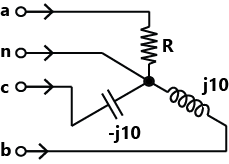
Sign in to UnlockA three-phase load is connected to a three-phase balanced supply as shown in the figure. If , and (angles are considered positive in the anti-clockwise direction), the value of R for zero current in the neutral wire is _______ (up to 2 decimal places).


Explanation Locked!
Unlock this branch to view the explanation, track, bookmark and more.
Sign in to UnlockThe per-unit power output of a salient-pole generator which is connected to an infinite bus, is given by the expression, where d is the load angle. Newton-Raphson method is used to calculate the value of for. If the initial guess is 30°, then its value (in degree) at the end of the first iteration is


28.47°

Explanation Locked!
Unlock this branch to view the explanation, track, bookmark and more.
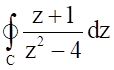
Sign in to UnlockThe value of the integral in counter clockwise direction around a circle C of radius 1 with centre at the point Z= -2 is


Explanation Locked!
Unlock this branch to view the explanation, track, bookmark and more.
Sign in to UnlockIn the logic circuit shown in the figure. Y is given by


Explanation Locked!
Unlock this branch to view the explanation, track, bookmark and more.
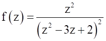
Sign in to UnlockIf C is a circle and , then is


Explanation Locked!
Unlock this branch to view the explanation, track, bookmark and more.
Sign in to UnlockDigital input signals A, B, C with A as the MSB and C as the LSB are used to realize the Boolean function
, Where to denote the minterm. In addition, F has a don't care for. The simplified expression for F is given by


Explanation Locked!
Unlock this branch to view the explanation, track, bookmark and more.
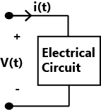
Sign in to UnlockIn the two-port network shown, the parameter (where, , when) in ohms is_______


(up to 2 decimal places)

Explanation Locked!
Unlock this branch to view the explanation, track, bookmark and more.
Sign in to UnlockConsider the two continuous-time signals defined below:


These signals are sampled with a sampling period of T=0.25 seconds to obtain discrete-time signalsand , respectively. Which one of the following statements is true?


The energy of is greater than the energy of.
The energy of is greater than the energy of.
and have equal energies.
Neither nor is a finite-energy signal.
Explanation Locked!
Unlock this branch to view the explanation, track, bookmark and more.
Sign in to UnlockThe signal energy of the continuous-time signal


Explanation Locked!
Unlock this branch to view the explanation, track, bookmark and more.
Sign in to UnlockThe Fourier transform of a continuous-time signal x(t) is given by ;, where and denotes frequency. Then the value of at t=1 is ______ (up to 1 decimal place). (In denotes the logarithm to base e)


Explanation Locked!
Unlock this branch to view the explanation, track, bookmark and more.
Sign in to UnlockA continuous-time input signal x(t) is an Eigen function of an LTI system, if the output is
, where k is an Eigen value

, where k is an Eigen function and is a complex exponential signal


due, where is a complex exponential signal

, where k is an Eigen function and is a frequency response of the system


Explanation Locked!
Unlock this branch to view the explanation, track, bookmark and more.
Sign in to UnlockThe number of roots of the polynomial, , in the open left half of the complex plane is

Explanation Locked!
Unlock this branch to view the explanation, track, bookmark and more.
Sign in to UnlockWhich one of the following statements is true about the digital circuit shown in the figure?

Explanation Locked!
Unlock this branch to view the explanation, track, bookmark and more.
Sign in to UnlockA bus admittance matrix for an electric power system has 8000 non-zero elements. The minimum number of branches (transmission lines and transformers) in this system is _____ (up to 2 decimal places).

Explanation Locked!
Unlock this branch to view the explanation, track, bookmark and more.
Sign in to UnlockA transformer with toroidal core of permeability is shown in the figure. Assuming uniform flux density across the circular core cross-section of radius, and neglecting any leakage flux, the best estimate for the mean radius R is


Explanation Locked!
Unlock this branch to view the explanation, track, bookmark and more.
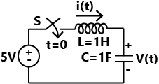
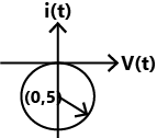
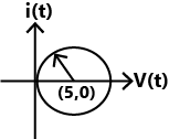
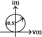
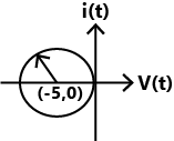
Sign in to UnlockA DC voltage source is connected to a series L-C circuit by taming on the switch S at time t-0 as shown in the figure. Assume. Which one of the following circular loci represents the plot of i(t) versus v(t)?

Explanation Locked!
Unlock this branch to view the explanation, track, bookmark and more.
Sign in to UnlockIn the circuit shown in the figure, the bipolar junction transistor (BJT) has a current gain. The base-emitter voltage drop is a constant. The value of the Thevenin equivalent resistance (in ) as shown in the figure is ________(up to 2 decimal places).


Explanation Locked!
Unlock this branch to view the explanation, track, bookmark and more.
Sign in to UnlockConsider a system governed by the following equations


The initial conditions are such that. Let and. Which one of the following is true?


Explanation Locked!
Unlock this branch to view the explanation, track, bookmark and more.
Sign in to UnlockLet f be a real-valued function of a real variable defined as, where denotes the largest integer less than or equal to x. The value ofis _______ (up 0.25 to 2 decimal places).


Explanation Locked!
Unlock this branch to view the explanation, track, bookmark and more.
Sign in to UnlockThe figure shows two buck converters connected in parallel. The common input DC voltage for the converters has a value of 100V. The converters have inductors of identical value. The load resistance is . The capacitor voltage has negligible ripple. Both converters operate in the continuous conduction mode. The switching frequency is 1 kHz, and the switch control signals are as shown. The circuit operates in the steady state. Assuming that the converters share the load equally, the average value of, the current of switch S1 (in Ampere), is ______ (up to 2 decimal places).


Explanation Locked!
Unlock this branch to view the explanation, track, bookmark and more.
Sign in to UnlockLet f be a real-valued function of a real variable defined as for, andfor x < 0. Which one of the following statements is true?


Explanation Locked!
Unlock this branch to view the explanation, track, bookmark and more.
Sign in to UnlockA DC to dc converter shown in the figure is charging a battery bank, B2 whose voltage is constant at 150V. B1 is another battery bank whose voltage is constant at 50V. The value of the inductor, L is 5mH and the ideal switch, S is operated with a switching frequency of 5 kHz with a duty ratio of 0.4. Once the circuit has attained steady state and assuming the diode D to be ideal, the power transferred from B1 to B2 (in Watt) is _____ (up to 2 decimal places).

Explanation Locked!
Unlock this branch to view the explanation, track, bookmark and more.
Sign in to UnlockFour power semiconductor devices are shown in the figure along with their relevant terminals. The device(s) that can carry dc current continuously in the direction shown when gated appropriately is (are)

Explanation Locked!
Unlock this branch to view the explanation, track, bookmark and more.
Sign in to UnlockThe value of the directional derivative of the functionat the point in the direction of the vectoris


Explanation Locked!
Unlock this branch to view the explanation, track, bookmark and more.
Sign in to UnlockLet. The maximum value of f(x) over the interval [0, 2] is _____ (up to 1 decimal place).

Explanation Locked!
Unlock this branch to view the explanation, track, bookmark and more.
Sign in to UnlockAs shown in the figure, C is the arc from the point (3, 0) to the point (0, 3) on the circle. The value of the integral is ________ (up to 2 decimal places).


Explanation Locked!
Unlock this branch to view the explanation, track, bookmark and more.
Sign in to UnlockConsider a unity feedback system with forward transfer function given by

The steady-state error in the output of the system for a unit-step input is______(up to 2 decimal places).
Explanation Locked!
Unlock this branch to view the explanation, track, bookmark and more.
Sign in to UnlockMatch the transfer functions of the second-order systems with the nature of the systems given below.
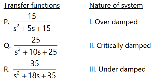
Explanation Locked!
Unlock this branch to view the explanation, track, bookmark and more.
Sign in to UnlockThe unit step response y(t) of a unity feedback system with open loop transfer function is shown in the figure.

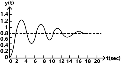
The value of K is ________ (up to decimal places).
Explanation Locked!
Unlock this branch to view the explanation, track, bookmark and more.
Sign in to UnlockConsider a non-singular square matrix A If and, the determinant of the matrix A is ________ (up to 1 decimal place).


Explanation Locked!
Unlock this branch to view the explanation, track, bookmark and more.
Sign in to UnlockA positive charge of 1nC is placed at (0, 0, 0.2) where all dimensions are in metres. Consider the x - y plane to be a conducting ground plane. Take . The Z component of the E field at (0, 0, 0.1) is closest to


Explanation Locked!
Unlock this branch to view the explanation, track, bookmark and more.
Sign in to UnlockLet and, where I is identity matrix. The determinant of B is ______ (up to 1 decimal place).


Explanation Locked!
Unlock this branch to view the explanation, track, bookmark and more.
Sign in to UnlockThe capacitance of an air-filled parallel-plate capacitor is 60pF. When a dielectric slab whose thickness is half the distance between the plates, is placed on one of the plates covering it entirely, the capacitance becomes 86pF. Neglecting the fringing effects, the relative permittivity of the dielectric is _______ (up to 2 decimal places).
Explanation Locked!
Unlock this branch to view the explanation, track, bookmark and more.
Sign in to UnlockThe series impedance matrix of a short three-phase transmission line in phase coordinates is

If the positive sequence impedance is and the zero sequence is , then the imaginary part of (in ) is _________(up to 2 decimal places).


Explanation Locked!
Unlock this branch to view the explanation, track, bookmark and more.
Sign in to UnlockThe positive, negative and zero sequence impedances of a 125 MVA, three-phase, 15.5 kV, star-grounded. 50 Hz generators are j0.1pu, j0.05pu and 10.01pu respectively on the machine rating base. The machine is unloaded and working at the rated terminal voltage. If the grounding impedance of the generator is j0.01pu, then the magnitude of fault current for a b-phase to ground fault (in kA) is _______ (up to 2 decimal places).
Explanation Locked!
Unlock this branch to view the explanation, track, bookmark and more.
Sign in to UnlockThe positive, negative and zero sequence impedances of a three phase generator are and respectively. For a line-to-line fault with fault impedance, the fault current is, where is the fault current with zero fault impedance. The relation between and k is


Explanation Locked!
Unlock this branch to view the explanation, track, bookmark and more.
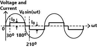
Sign in to UnlockThe waveform of the current drawn by a semi-converter from a sinusoidal AC voltage I source is shown in the figure. If , the RMS value of fundamental component of the current is _______ A (up to 2 decimal places).

Explanation Locked!
Unlock this branch to view the explanation, track, bookmark and more.
Sign in to UnlockIn the figure, the voltages are , and


. The circuit is in sinusoidal steady state, and, and are the average power outputs. Which one of the following statements is true?


Explanation Locked!
Unlock this branch to view the explanation, track, bookmark and more.
Sign in to UnlockA single phase fully controlled rectifier is supplying a load with an anti-parallel diode as shown in the figure. All switches and diodes are ideal. Which one of the following is true for instantaneous load voltage and current?

&


&

&

&
Explanation Locked!
Unlock this branch to view the explanation, track, bookmark and more.
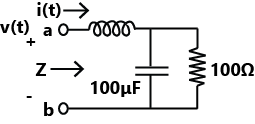
Sign in to UnlockThe voltage v(t) across the terminals a and b as shown in the figure, is a sinusoidal voltage having a frequency . When the inductor current i(t) is in phase with the voltage v(t), the magnitude of the impedance Z (in ) seen between the terminals a and is _______ (up to 2 decimal places).


Explanation Locked!
Unlock this branch to view the explanation, track, bookmark and more.
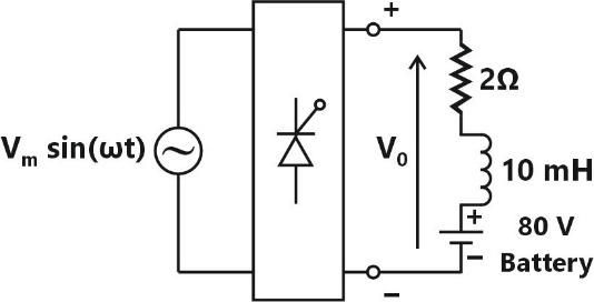
Sign in to UnlockA phase controlled signal phase reflector, supplied by an AC source, feeds power to an R-L-E load as shown in the figure. The reflector output voltage has an average value given by , where and is the firing angle. If the power delivered to the loss less battery is 1600W, in degree is ______ (up to 2 decimal places)


Explanation Locked!
Unlock this branch to view the explanation, track, bookmark and more.
Sign in to UnlockThe voltage across the circuit in the figure, and the current through it are given by the following expressions:


Where , If the average power delivered to the circuit is zero then the value of X (in Ampere) is ________ (up to 2 decimal places).

Explanation Locked!
Unlock this branch to view the explanation, track, bookmark and more.
Sign in to UnlockThe op-amp shown in the figure is ideal. The input impedance is given by


Z

Explanation Locked!
Unlock this branch to view the explanation, track, bookmark and more.
Sign in to UnlockIn a salient pole synchronous motor, the developed reluctance torque attains the maximum value when the load angle in electrical degrees is
Explanation Locked!
Unlock this branch to view the explanation, track, bookmark and more.
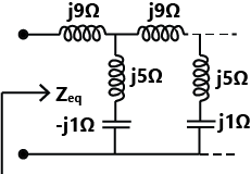
Sign in to UnlockThe equivalent impedance for the infinite ladder circuit shown in the figure is


Explanation Locked!
Unlock this branch to view the explanation, track, bookmark and more.
Sign in to UnlockA separately excited dc motor has an armature resistance. The field excitation is kept constant. At an armature voltage of 100V, the motor produces a torque of 500 Nm at zero speed. Neglecting all mechanical losses, the no-load speed of the motor (in radian/s) for an armature voltage of 150 V is _______ (up to 2 decimal places).

Explanation Locked!
Unlock this branch to view the explanation, track, bookmark and more.
Sign in to UnlockTwo wattmeter method is used for measurement of power in a balanced three-phase load supplied from a balanced three-phase system. If one of the watt-meters reads half of the other (both positive), then the power factor of the load is
Explanation Locked!
Unlock this branch to view the explanation, track, bookmark and more.
Sign in to UnlockA 200V DC series motor, when operating from rated voltage while driving a certain load, draws 10 A current and runs at 1000r.p.m. The total series resistance is . The magnetic circuit is assumed to be linear. At the same supply voltage, the load torque is increased by 44%. The speed of the motor in r.p.m. (rounded to the nearest integer) is ________

Explanation Locked!
Unlock this branch to view the explanation, track, bookmark and more.
Sign in to UnlockA 0-1 Ampere moving iron ammeter has an internal resistance of and inductance of 0.1mH. A shunt coil is connected to extend its range to 0-10 Ampere for all operating frequencies. The time constant in milliseconds and resistance in of the shunt coil respectively are


Explanation Locked!
Unlock this branch to view the explanation, track, bookmark and more.
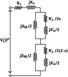
Sign in to UnlockThe equivalent circuit of a single phase induction motor is shown in the figure, where the parameters are and S is the slip. At no-load, the motor speed can be approximated to be the synchronous speed. The no-load lagging power factor of the motor is ________ (up to 3 decimal places).


Explanation Locked!
Unlock this branch to view the explanation, track, bookmark and more.
Sign in to UnlockA single-phase 100kVA, 1000V/100 V. 50 Hz transformer has a voltage drop of 5% across its series impedance at full load. Of this, 3% is due to resistance. The percentage regulation of the transformer at full load with 0.8 lagging power factor is
Explanation Locked!
Unlock this branch to view the explanation, track, bookmark and more.
Sign in to UnlockA 3-phase 900kVA, , 50Hz transformer has primary (high voltage side) resistance per phase of and secondary (low voltage side) resistance per phase of . Iron loss of the transformer is 10kW. The full load % efficiency of the transformer operated at unity power factor is ______ (up to 2 decimal places).


Explanation Locked!
Unlock this branch to view the explanation, track, bookmark and more.
Sign in to UnlockConsider a lossy transmission line with and as the sending and receiving end voltages, respectively. Z and X are the series impedance and reactance of the line, respectively. The steady-state stability limit for the transmission line will be


Greater than

Less than
equal to
equal to
Explanation Locked!
Unlock this branch to view the explanation, track, bookmark and more.
Sign in to UnlockConsider the two bus power system network with given loads as shown in the figure. All the values shown in the figure are in per unit. The reactive power supplied by generator and are and respectively. The per unit values of and line reactive power loss respectively are


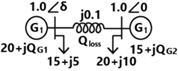
Explanation Locked!
Unlock this branch to view the explanation, track, bookmark and more.
Sign in to Unlock