
A current of is passed through three meters. They are a centre zero PMMC meter, a true rms meter and a moving iron instrument. The respective reading (in A) will be
Explanation Locked!
Unlock this branch to view the explanation, track, bookmark and more.
Sign in to UnlockThe discrete time signal , where ↔ denotes a transform-pair relationship, is orthogonal to the signal.


Explanation Locked!
Unlock this branch to view the explanation, track, bookmark and more.
Sign in to Unlocky[n] denotes the output and x[n] denotes the input of a discrete-time system given by the difference equation y[n] – 0.8y[n – 1] = x[n] + 1.25x[n + 1]. Its right-sided impulse response is
Explanation Locked!
Unlock this branch to view the explanation, track, bookmark and more.
Sign in to UnlockTwo fair dice are rolled and the sum r of the numbers turned is considered.


Explanation Locked!
Unlock this branch to view the explanation, track, bookmark and more.
Sign in to Unlockx[n] = 0; n <-1&n>0, x[-1]=-1, x[0]=2 is the input and y[n]=0; n<-1&n>2, y[-1]=–1=y[1], y[0]=3, y[2]=-2 is the output of a discrete time LTI system. The system impulse response h[n] will be
Explanation Locked!
Unlock this branch to view the explanation, track, bookmark and more.
Sign in to UnlockA discrete real all pass system has a pole at : it, therefore
also has a pole at

has a constant phase response over the -plane:


is stable only if it is anti-causal
has a constant phase response over the unit circle:

Explanation Locked!
Unlock this branch to view the explanation, track, bookmark and more.
Sign in to UnlockThe expression for the volume of a cone is equal to


Explanation Locked!
Unlock this branch to view the explanation, track, bookmark and more.
Sign in to UnlockAn energy meter connected to an immersion heater (resistive) operating on an AC 230 V, 50 Hz, AC single phase source reads 2.3 units (kWh) in 1 hour. The heater is removed from the supply and now connected to a 400 V peak square wave source of 150 Hz. The power in kW dissipated by the heater will be
Explanation Locked!
Unlock this branch to view the explanation, track, bookmark and more.
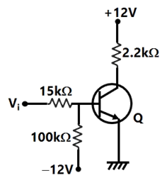
Sign in to UnlockA TTL NOT gate circuit is shown in figure. Assuming VBE = 0.7V of both the transistors, if Vi = 3.0 V, then the states of the two transistors will be
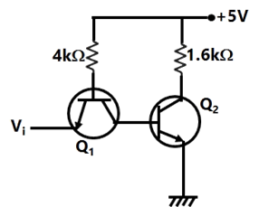
ON and OFF


reverse ON and OFF
reverse ON and ON
OFF and reverse ON
Explanation Locked!
Unlock this branch to view the explanation, track, bookmark and more.
Sign in to UnlockA continuous time system is described by , where y(t) is the output and x(t) is the input. y(t) is bounded

Only when x(t) is bounded
Only when x(t) is non-negative
Only for if x(t) is bounded for

Even when x(t) is not bounded.
Explanation Locked!
Unlock this branch to view the explanation, track, bookmark and more.
Sign in to UnlockThe running integrator, given by

Explanation Locked!
Unlock this branch to view the explanation, track, bookmark and more.
Sign in to UnlockA surface S(x, y) = 2x + 5y − 3 is integrated once over a path consisting of the points that satisfy. The integral evaluates to


0
Explanation Locked!
Unlock this branch to view the explanation, track, bookmark and more.
Sign in to UnlockA variable w is related to three other variables x, y, z as . The variables are measured with meters of accuracy ±0.5% reading, ±1%of full scale value and ±1.5% reading. The actual readings of the three meters are 80, 20 and 50 with 100 being the full scale value for all three. The maximum uncertainty in the measurement of w will be

Explanation Locked!
Unlock this branch to view the explanation, track, bookmark and more.
Sign in to Unlockand are the opposite arms of a Wheatstone bridge as are and . The source voltage is applied across and . Under balanced conditions which one of the following is true?


Explanation Locked!
Unlock this branch to view the explanation, track, bookmark and more.
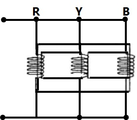
Sign in to UnlockThe three limbed non ideal core shown in the figure has three windings with nominal inductances L each when measured individually with a single phase AC source.
The inductance of the windings as connected will be
Explanation Locked!
Unlock this branch to view the explanation, track, bookmark and more.
Sign in to Unlockx(t) is a real valued function of a real variable with period T. Its trigonometric Fourier Series expansion contains no terms of frequency ω = 2π (2k)/T; k = 1, 2,…… Also, no sine terms are present. Then x(t) satisfies the equation


Explanation Locked!
Unlock this branch to view the explanation, track, bookmark and more.
Sign in to UnlockA 200/1 current transformer (CT) is wound with 200 turns on the secondary on a toroidal core. When it carries a current of 160 A on the primary, the ratio and phase errors of the CT are found to be -0.5% and 30 minutes respectively. If the number of secondary turns is reduced by 1 the new ratio error (%) and phase error (min) will be respectively
Explanation Locked!
Unlock this branch to view the explanation, track, bookmark and more.
Sign in to UnlockA closed loop system has the characteristic function . Its root locus plot against K is

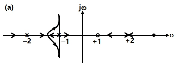
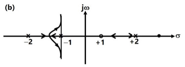
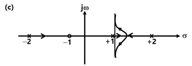
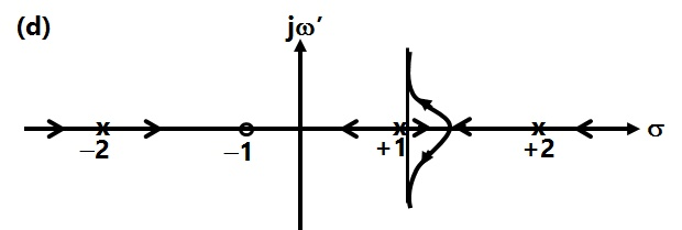
Explanation Locked!
Unlock this branch to view the explanation, track, bookmark and more.
Sign in to UnlockWhich of the following is true
A finite signal is always bounded
A bounded signal always possesses finite energy
A bounded signal is always zero outside the interval for some


None
Explanation Locked!
Unlock this branch to view the explanation, track, bookmark and more.
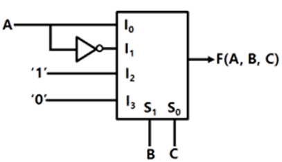
Sign in to UnlockA 4 × 1 MUX is used to implement a 3-input Boolean function as shown in figure. The Boolean function F(A, B, C) implemented is


Explanation Locked!
Unlock this branch to view the explanation, track, bookmark and more.
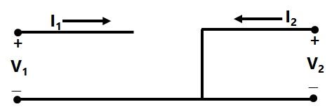
Sign in to UnlockThe parameter type and the matrix representation of the relevant two port parameters that describe the circuit shown are
z parameters,

h parameters,

h parameters,
z parameters,
Explanation Locked!
Unlock this branch to view the explanation, track, bookmark and more.
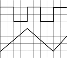
Sign in to UnlockThe time/div and voltage/div axes of an oscilloscope have been erased. A student connects a 1 kHz, 5V p-p square wave calibration pulse to channel 1 of the scope and observes the screen to be as shown in the upper trace of the figure. An unknown signal is connected to channel 2 (lower trace) of the scope. If the time/div and V/div on both channels are the same, the amplitude (p-p) and period of the unknown signal are respectively
Explanation Locked!
Unlock this branch to view the explanation, track, bookmark and more.
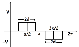
Sign in to UnlockA single phase inverter is operated in PWM mode generating a single-pulse of width 2d in the center of each half cycle as shown in figure. It is found that the output voltage is free from 5th harmonic for pulse width 144°. What will be percentage of 3rd harmonic present in the output voltage?

Explanation Locked!
Unlock this branch to view the explanation, track, bookmark and more.
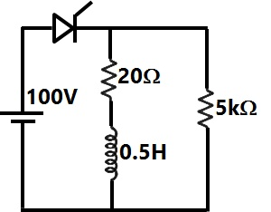
Sign in to UnlockWhat are the states of the three ideal diodes of the circuit shown in figure?
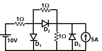
ON, OFF, OFF


OFF, ON, OFF
ON, OFF, ON
OFF, ON, ON
Explanation Locked!
Unlock this branch to view the explanation, track, bookmark and more.
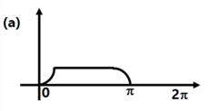
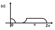
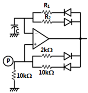
Sign in to UnlockAssuming the diodes and of the circuit shown in figure to be ideal ones, the transfer characteristics of the circuit will be


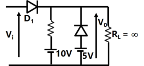
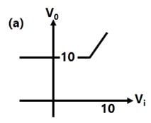
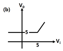
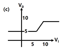
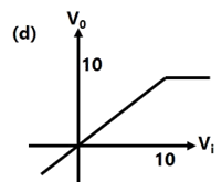
Explanation Locked!
Unlock this branch to view the explanation, track, bookmark and more.
Sign in to UnlockThe algebraic equation is given F(s) = 0 has

Explanation Locked!
Unlock this branch to view the explanation, track, bookmark and more.
Sign in to UnlockThe Gauss Seidel load flow has following disadvantages. Tick the incorrect statement.
Explanation Locked!
Unlock this branch to view the explanation, track, bookmark and more.
Sign in to UnlockA student has made a 3-bit binary down counter and connected to the R- 2R ladder type DAC [Gain = (-1 kΩ/2R)] as shown in figure to generate a staircase waveform. The output achieved is different as shown in figure. What could be the possible cause of this error?
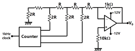

Explanation Locked!
Unlock this branch to view the explanation, track, bookmark and more.
Sign in to UnlockIt is required to design an anti-aliasing filter for an 8 bit ADC. The filter is a first order RC filter with R = 1Ω and C = 1F. The ADC is designed to span a sinusoidal signal with peak to peak amplitude equal to the full range of the ADC.

The transfer function of the filter and its roll off respectively are
dB/decade

dB/decade

dB/decade

dB/decade

Explanation Locked!
Unlock this branch to view the explanation, track, bookmark and more.
Sign in to UnlockIt is required to design an anti-aliasing filter for an 8 bit ADC. The filter is a first order RC filter with R = 1W and C = 1F. The ADC is designed to span a sinusoidal signal with peak to peak amplitude equal to the full range of the ADC.

What is the SNR (in dB) of the ADC? Also find the frequency (in decades) at the filter output at which the filter attenuation just exceeds the SNR of the ADC.
Explanation Locked!
Unlock this branch to view the explanation, track, bookmark and more.
Sign in to Unlockare three vectors

An orthogonal set of vectors having a span that contains p, q, r is


Explanation Locked!
Unlock this branch to view the explanation, track, bookmark and more.
Sign in to UnlockFor a system with the transfer function, the matrix A in the state space from is equal to


Explanation Locked!
Unlock this branch to view the explanation, track, bookmark and more.
Sign in to Unlockare three vectors
The following vector is linearly dependent upon the solution to the previous problem


Explanation Locked!
Unlock this branch to view the explanation, track, bookmark and more.
Sign in to UnlockA voltage commutated chopper operating at 1 kHz is used to control the speed of dc motor as shown in figure. The load current is assumed to be constant at 10 A.

The minimum time in µsec for which the SCR M should be ON is
Explanation Locked!
Unlock this branch to view the explanation, track, bookmark and more.
Sign in to UnlockA software delay subroutine is written as given below:
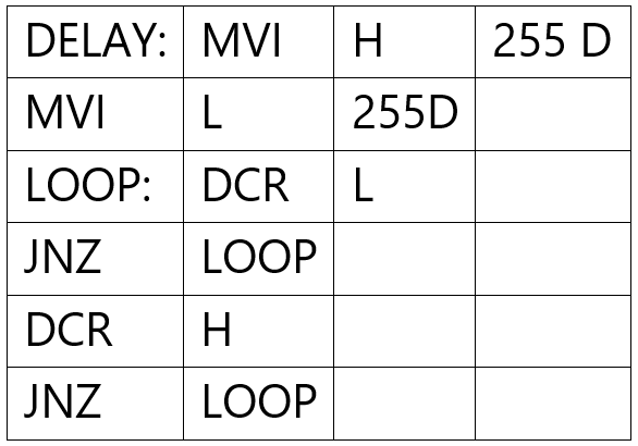
How many times DCR L instruction will be executed?
Explanation Locked!
Unlock this branch to view the explanation, track, bookmark and more.
Sign in to UnlockA generator feeds power to an infinite bus through a double circuit transmission line. A 3 phase fault occurs at the middle point of one of the lines. The infinite bus voltage is 1 pu., the transient internal voltage of the generator is 1.1 pu. & the equivalent transfer admittance during fault is 0.8 pu. The 100 MVA generator has an inertia constant of 5 MJ/MVA & it was delivering 1 pu power prior to the fault with rotor power angle of 30°. The system frequency is 50 Hz.
The initial accelerating power (in pu) will be
Explanation Locked!
Unlock this branch to view the explanation, track, bookmark and more.
Sign in to UnlockA voltage commutated chopper operating at 1 kHz is used to control the speed of dc motor as shown in figure. The load current is assumed to be constant at 10 A.
The average output voltage of the chopper will be
Explanation Locked!
Unlock this branch to view the explanation, track, bookmark and more.
Sign in to UnlockIn an 8085 microprocessor based system, it is desired to increment the contents of memory location whose address is available in (D, E) register pair and store the result in same location. The sequence of instructions is
Explanation Locked!
Unlock this branch to view the explanation, track, bookmark and more.
Sign in to UnlockA generator feeds power to an infinite bus through a double circuit transmission line. A 3 phase fault occurs at the middle point of one of the lines. The infinite bus voltage is 1 pu., the transient internal voltage of the generator is 1.1 pu. & the equivalent transfer admittance during fault is 0.8 pu. The 100 MVA generator has an inertia constant of 5 MJ/MVA & it was delivering 1 pu power prior to the fault with rotor power angle of 30°. The system frequency is 50 Hz.
If the initial accelerating power is X pu, the initial acceleration in , and the inertia constant in MJ-sec/select deg respectively will be

Explanation Locked!
Unlock this branch to view the explanation, track, bookmark and more.
Sign in to UnlockWhich of the following statements holds for the divergence of electric and magnetic flux densities
Explanation Locked!
Unlock this branch to view the explanation, track, bookmark and more.
Sign in to UnlockConsider the circuit shown in figure. If the β of the transistor is 39 and is 20nA and the input voltage is +5V, then transistor would be operating in

Explanation Locked!
Unlock this branch to view the explanation, track, bookmark and more.
Sign in to UnlockConsider the following statements with reference to the equation

(1) This is a point format the continuity equation
(2) Divergence of current density is equal to the decrease of charge per unit volume per unit at every point
(3) This is Maxwell’s divergence equation
(4) This represents the conservation of charge
Select the correct answer
Explanation Locked!
Unlock this branch to view the explanation, track, bookmark and more.
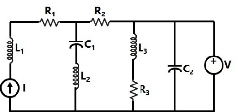
Sign in to UnlockIn the circuit shown in the figure, the current source I = 1A, voltage source V = 5V, , ,


In steady state, the currents (in A) through R3 and the voltage source V respectively will be
Explanation Locked!
Unlock this branch to view the explanation, track, bookmark and more.
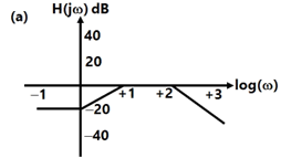
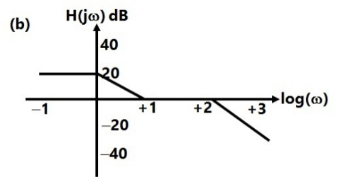
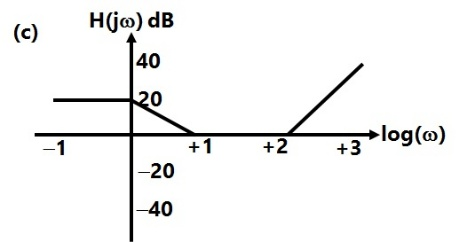
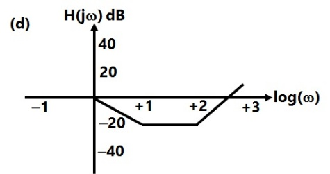
Sign in to UnlockThe Bode magnitude plot of is

Explanation Locked!
Unlock this branch to view the explanation, track, bookmark and more.
Sign in to UnlockKeeping in view the cost and overall effectiveness, the following circuit breaker is best suited for capacitor bank switching.
Explanation Locked!
Unlock this branch to view the explanation, track, bookmark and more.
Sign in to UnlockAn ideal capacitor is charged to a voltage V0 and connected at t = 0 across an ideal inductor L. (The circuit now consists of a capacitor and inductor alone). If we let , the voltage across the capacitor at time t > 0 is given by

V0


Explanation Locked!
Unlock this branch to view the explanation, track, bookmark and more.
Sign in to UnlockA voltage commutation circuit is shown in figure. If the turn off time of the SCRs is 50µ sec and a safety margin of 2 is considered, then what will be the approximate minimum value of capacitor required for proper commutation?

Explanation Locked!
Unlock this branch to view the explanation, track, bookmark and more.
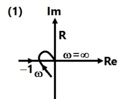
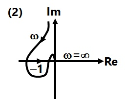
Sign in to UnlockConsider the following Nyquist plots of loop transfer functions over ω = 0 to ω= ∞. Which of these plots represents a stable closed loop system?
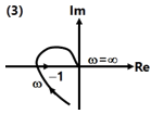
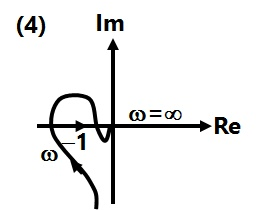
Explanation Locked!
Unlock this branch to view the explanation, track, bookmark and more.
Sign in to UnlockIn a biased differential relay, the bias is defined as a ratio of
Explanation Locked!
Unlock this branch to view the explanation, track, bookmark and more.
Sign in to UnlockAn SCR having a turn ON time of 5µsec, latching current of 50mA and holding current of 40mA is triggered by a short duration pulse and is used in the circuit shown in figure. The minimum pulse width required to turn the SCR ON will be
Explanation Locked!
Unlock this branch to view the explanation, track, bookmark and more.
Sign in to UnlockA single-phase half wave uncontrolled converter circuit is shown in figure. A 2-winding transformer is used at the input for isolation. Assuming the load current to be constant and, the current waveform through diode will be


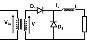


Explanation Locked!
Unlock this branch to view the explanation, track, bookmark and more.
Sign in to UnlockThe identical star connected resistors of 1.0pu are connected to an unbalanced 3 phase supply. The load neutral is isolated. The symmetrical components of the line voltages n pu are: . If all the pu calculations are with the respective base values, the phase to neutral sequence voltages are


Explanation Locked!
Unlock this branch to view the explanation, track, bookmark and more.
Sign in to UnlockA generator is connected through a 20 MVA 13.8/138 kV step-up transformer, to a transmission line. At the receiving end of the line a load is supplied through a step down transformer of 10 MVA, 138/69 kV rating. A 0.72 pu load, evaluated on load side transformer ratings as base values, is supplied from the above system. For system base values of 10 MVA and 69 kV in load circuit, the value of the load (in per unit) in generator circuit will be
Explanation Locked!
Unlock this branch to view the explanation, track, bookmark and more.
Sign in to UnlockA 3-phase fully controlled bridge converter with freewheeling diode is fed from 400 V, 50 Hz AC source and is operating at a firing angle of 60°. The load current is assumed constant at 10A due to high load inductance. The input displacement factor (IDF) and the input power factor (IPF) of the converter will be
Explanation Locked!
Unlock this branch to view the explanation, track, bookmark and more.
Sign in to UnlockA solar cell of 350 V is feeding power to an ac supply of 440V, 50 Hz through a 3-phase fully controlled bridge converter. A large inductance is connected in the dc circuit to maintain the dc current at 20A. If the solar cell resistance is 0.5Ω, then each thyristor will be reverse biased for a period of
Explanation Locked!
Unlock this branch to view the explanation, track, bookmark and more.
Sign in to UnlockFor a power system and admittance and impedance matrices for the fault studies are a follows:


The pre fault voltages are 1.0 p.u at all the buses. The system was unloaded prior to the fault. A solid 3 phase fault takes place at bus 2.
The post fault voltages at buses 1 and 3 in per unit respectively are
Explanation Locked!
Unlock this branch to view the explanation, track, bookmark and more.
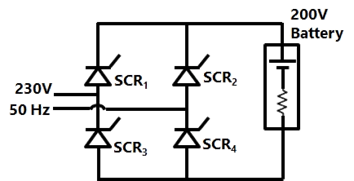
Sign in to UnlockA single-phase bridge converter is used to charge a battery of 200V having an internal resistance of 2Ω as shown in figure. The SCR’s are triggered by a constant dc signal. If SCR 2 gets open circuited, then what will be average charging current?
Explanation Locked!
Unlock this branch to view the explanation, track, bookmark and more.
Sign in to UnlockFor a power system and admittance and impedance matrices for the fault studies are a follows:
The pre fault voltages are 1.0 p.u at all the buses. The system was unloaded prior to the fault. A solid 3 phase fault takes place at bus 2.
The per unit fault feeds from generators connected to buses 1 and 2 respectively are
Explanation Locked!
Unlock this branch to view the explanation, track, bookmark and more.
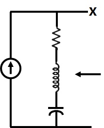
Sign in to UnlockIn the figure the current source is 1∠0 A, R=1Ω, the impedances are , and . The Thevenin equivalent looking into the circuit across X-Y is


Explanation Locked!
Unlock this branch to view the explanation, track, bookmark and more.
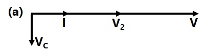
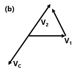
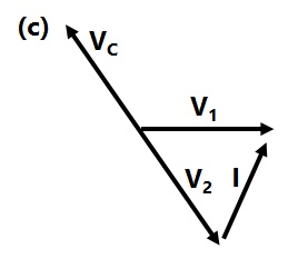
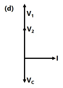
Sign in to UnlockThe circuit shown in the figure is energized by a sinusoidal voltage source at a frequency which causes resonance with a current of I.

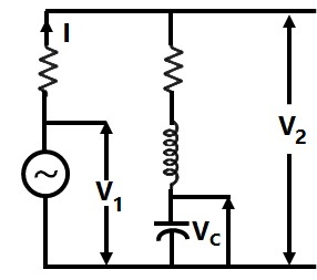
The phasor diagram which is applicable to this circuit is
Explanation Locked!
Unlock this branch to view the explanation, track, bookmark and more.
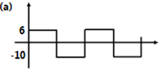
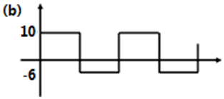
Sign in to UnlockFor a given sinusoidal input voltage, the voltage waveform at point P of the clamper circuit shown in figure will be


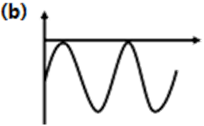
1


Explanation Locked!
Unlock this branch to view the explanation, track, bookmark and more.
Sign in to UnlockThe parameters of the circuit shown in the figure are. If , then output voltage, input impedance and output impedance respectively are


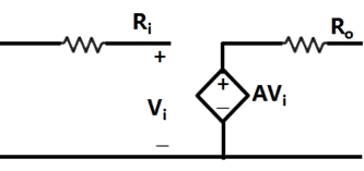


Explanation Locked!
Unlock this branch to view the explanation, track, bookmark and more.
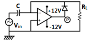
Sign in to UnlockA relaxation oscillator is made using OPAMP as shown in figure. The supply voltages of the OPAMP are ±12V. The voltage waveform at point P will be


Explanation Locked!
Unlock this branch to view the explanation, track, bookmark and more.
Sign in to UnlockA synchronous generator is feeding a zero power factor (lagging) load at rated current. The armature reaction is
Explanation Locked!
Unlock this branch to view the explanation, track, bookmark and more.
Sign in to UnlockA 3 phase, 400 V, 5 kW, star connected synchronous motor having an internal reactance of 10Ω is operating at 50% load, unit pf. Now, the excitation is increased by 1%. What will be the new load in percent, if the power factor is to be kept same? Neglect all losses and consider linear magnetic circuit.
Explanation Locked!
Unlock this branch to view the explanation, track, bookmark and more.
Sign in to UnlockA 4 pole, 50 Hz synchronous generator has 48 slots in which a double layer winding is housed. Each coil has 10 turns and is short pitched by an angle to 36° electrical. The fundamental flux per pole is 0.025Wb.
The line-to-line induced EMF (in volts). For a three phase star connection is approximately
Explanation Locked!
Unlock this branch to view the explanation, track, bookmark and more.
Sign in to UnlockIn a DC machine, which of the following statements is true?
Explanation Locked!
Unlock this branch to view the explanation, track, bookmark and more.
Sign in to UnlockA 4 pole, 50 Hz synchronous generator has 48 slots in which a double layer winding is housed. Each coil has 10 turns and is short pitched by an angle to 36° electrical. The fundamental flux per pole is 0.025Wb.
The line-to-line induced EMF (in volts), for a two phase connection is approximately
Explanation Locked!
Unlock this branch to view the explanation, track, bookmark and more.
Sign in to UnlockA 220 V DC machine supplies 20A at 200 V as a generator. The armature resistance is 0.2 ohm. If the machine is now operated as a motor at same terminal voltage and current but with the flux increased by 10%, then ratio of motor speed to generator speed is
Explanation Locked!
Unlock this branch to view the explanation, track, bookmark and more.
Sign in to UnlockA 4 pole, 50 Hz synchronous generator has 48 slots in which a double layer winding is housed. Each coil has 10 turns and is short pitched by an angle to 36° electrical. The fundamental flux per pole is 0.025Wb.
The fifth harmonic component of phase emf
(in volts), for a three phase star connection is
Explanation Locked!
Unlock this branch to view the explanation, track, bookmark and more.
Sign in to UnlockA sampling wattmeter (that computes power from simultaneously sampled values of voltage and current) is used to measure the average power of a load. The peak to peak voltage of the square wave is 10 V and the current is a triangular wave of 5A p-p as shown in the figure. The period is 20ms. The reading in W will be


Explanation Locked!
Unlock this branch to view the explanation, track, bookmark and more.
Sign in to UnlockIn transformers, which of the following statements is valid?
Explanation Locked!
Unlock this branch to view the explanation, track, bookmark and more.
Sign in to UnlockFor a single phase capacitor start induction motor which of the following statements is valid?
Explanation Locked!
Unlock this branch to view the explanation, track, bookmark and more.
Sign in to UnlockTwo transformers are to be operated in parallel such that they share load in proportion to their kVA ratings. The rating of the first transformer is 500 kVA and its pu leakage impedance is 0.05 pu. If the rating of second transformer is 250 kVA, then its pu leakage impedance is
Explanation Locked!
Unlock this branch to view the explanation, track, bookmark and more.
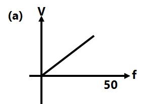
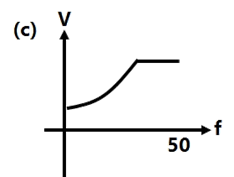
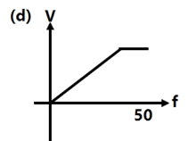
Sign in to UnlockThe speed of a 3-phase, 440 V, 50 Hz induction motor is to be controlled over a wide range from zero speed to 1.5 times the rated speed using a 3-phase voltage source inverter. It is desired to keep the flux in
the machine constant in the constant torque region by controlling the terminal voltage as the frequency changes. The inverter output voltage vs frequency characteristics should be

Explanation Locked!
Unlock this branch to view the explanation, track, bookmark and more.
Sign in to UnlockA 300 kVA transformer has 95% efficiency at full load 0.8 pf lagging and 96% efficiency at half load, unity pf.
The iron loss and copper loss in kW, under full load operation are


= 4.12, = 8.51


= 6.59, = 9.21
= 8.51, = 4.12
= 12.72, = 3.07
Explanation Locked!
Unlock this branch to view the explanation, track, bookmark and more.
Sign in to UnlockThe speed of a 4-pole induction motor is controlled by varying the supply frequency while maintaining the ratio of supply voltage to supply frequency (V/fJ constant. At rated frequency of 50 Hz and rated voltage of 400 V its speed is 1440 rpm. Find the speed at 30 Hz, if the load torque is constant.
Explanation Locked!
Unlock this branch to view the explanation, track, bookmark and more.
Sign in to UnlockA 300 kVA transformer has 95% efficiency at full load 0.8 pf lagging and 96% efficiency at half load, unity pf.
What is the maximum efficiency (in %) at unity pf load?
Explanation Locked!
Unlock this branch to view the explanation, track, bookmark and more.
Sign in to UnlockA 3 phase, 4 poles, 400 V, 50 Hz, star connected induction motor has following circuit parameters. The starting torque when the motor is started direct-on-line is (use approximate equivalent circuit model)

Explanation Locked!
Unlock this branch to view the explanation, track, bookmark and more.
Sign in to UnlockA 3 phase, 10 kW, 400 V, 4 pole, 50 Hz, star connected induction motor draws 20A on full load. It’s no load and blocked rotor test data are given below:
No Load test : 400 V 6A 1002 W
Blocked Rotor test : 90 V 15A 762 W
Neglecting copper loss in no Load test and core loss in Blocked Rotor test, estimate motor’s full load efficiency
Explanation Locked!
Unlock this branch to view the explanation, track, bookmark and more.
Sign in to UnlockThe concept of an electrically short, medium and long line is primarily based on the
Explanation Locked!
Unlock this branch to view the explanation, track, bookmark and more.
Sign in to UnlockAn HVDC link consists of rectifier, inverter transmission line and other equipment’s. Which one of the following is true for this link?
Explanation Locked!
Unlock this branch to view the explanation, track, bookmark and more.
Sign in to UnlockA 400V, 50 Hz, three phase balanced source supplies power to a star connected load whose rating is kVA, 0.8 pf (lag). The rating (in kVAR) of the delta connected (capacitive) reactive power bank necessary to bring the pf to unity is

Explanation Locked!
Unlock this branch to view the explanation, track, bookmark and more.
Sign in to UnlockThe A, B, C, D constants of a 220 kV line are: , , . If the sending end voltage of the line for a given load delivered at nominal voltage is 240 kV, then % voltage regulation of the line is


Explanation Locked!
Unlock this branch to view the explanation, track, bookmark and more.
Sign in to UnlockA single phase transmission line and a telephone line are both symmetrically strung one below the other, in horizontal configurations, on a common tower. The shortest and longest distances between the phase and telephone conductors are 2.5 m and 3 m respectively. The voltage (volt/km) inducted in the telephone circuit, due to 50 Hz current of 100 amps in the power circuit is
Explanation Locked!
Unlock this branch to view the explanation, track, bookmark and more.
Sign in to Unlock