
A digit DMM has the error specification as: 0.2% of reading + 10 counts. If a dc voltage of 100V is read on its 200V full scale, the maximum error that can be expected in the reading is

Explanation Locked!
Unlock this branch to view the explanation, track, bookmark and more.
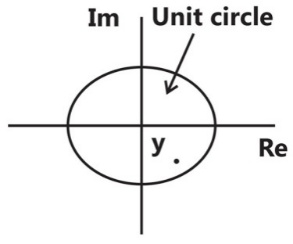
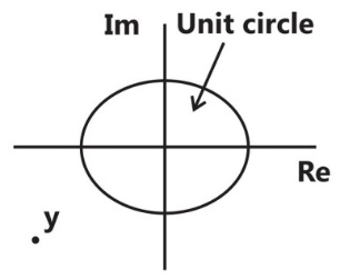
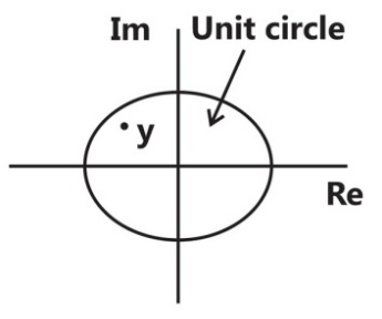
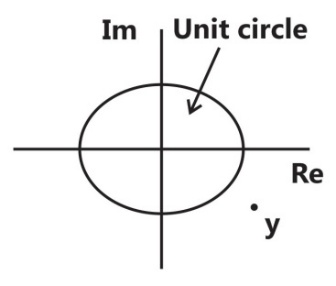
Sign in to UnlockA point z has been plotted in the complex plane, as shown in figure below.
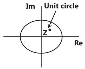
The plot of the complex number is

Explanation Locked!
Unlock this branch to view the explanation, track, bookmark and more.
Sign in to UnlockWith K as a constant, the possible solution for the first order differential equation is


Explanation Locked!
Unlock this branch to view the explanation, track, bookmark and more.
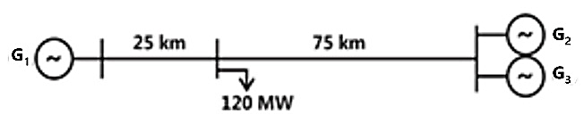
Sign in to UnlockA load center of 120MW derives power from two power stations connected by 220kV transmission lines of 25km and 75km as shown in the figure below. The three generators , and are of 100MW capacity each and have identical fuel cost characteristics. The minimum loss generation schedule for supplying the 120MW load is


= 80MW + losses

= 20MW

= 20 MW

= 60MW
= 30MW +losses
= 30MW
= 40MW
= 40MW
= 40MW + losses
= 30MW + losses
= 45MW
= 45MW
Explanation Locked!
Unlock this branch to view the explanation, track, bookmark and more.
Sign in to UnlockSolution of the variables and for the following equations is to be obtained by employing the Newton-Raphson iterative method.


Equation (i)

Equation (ii)

Assuming the initial values and , the Jacobian matrix is


Explanation Locked!
Unlock this branch to view the explanation, track, bookmark and more.
Sign in to UnlockGiven two continuous time signals and which exist for t > 0, the convolution is


Explanation Locked!
Unlock this branch to view the explanation, track, bookmark and more.
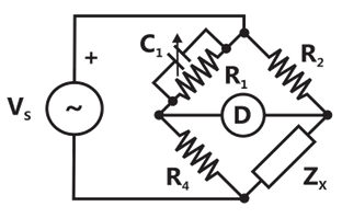
Sign in to UnlockThe bridge circuit shown in the figure below is used for the measurement of an unknown element. The bridge circuit is best suited when is a

Explanation Locked!
Unlock this branch to view the explanation, track, bookmark and more.
Sign in to UnlockLet the Laplace transform of a function f(t) which exists for t > 0 be and the Laplace transform of its delayed version be . Let be the complex conjugate of with the Laplace variable set as .If , then the inverse Laplace transform of G(s) is


An ideal impulse

An ideal delayed impulse

An ideal step function u(t)
An ideal delayed step function

Explanation Locked!
Unlock this branch to view the explanation, track, bookmark and more.
Sign in to UnlockThe output Y of the logic circuit given below is

1
0
X

Explanation Locked!
Unlock this branch to view the explanation, track, bookmark and more.
Sign in to UnlockThe open loop transfer function G(s) of a unity feedback control system is given as,1

From the root locus, it can be inferred that when k tends to positive infinity,
three roots with nearly equal real parts exist on the left half of the s-plane
one real root is found on the right half of the s-plane
the root loci cross the axis for a finite value of k;


three real roots are found on the right half of the s-plane
Explanation Locked!
Unlock this branch to view the explanation, track, bookmark and more.
Sign in to UnlockA lossy capacitor , rated for operation at 5kV, 50Hz is represented by an equivalent circuit with an ideal capacitor in parallel with a resistor . The value of is found to be 0.102µF and the value of .Then the power loss and of the lossy capacitor operating at the rated voltage, respectively, are


Explanation Locked!
Unlock this branch to view the explanation, track, bookmark and more.
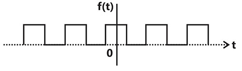
Sign in to UnlockThe Fourier series expansion of the periodic signal shown below will contain the following nonzero terms


Explanation Locked!
Unlock this branch to view the explanation, track, bookmark and more.
Sign in to UnlockA zero mean random signal is uniformly distributed between limits –a and +a and its mean square value is equal to its variance. Then the RMS value of the signal is


Explanation Locked!
Unlock this branch to view the explanation, track, bookmark and more.
Sign in to UnlockThe response h(t) of a linear time invariant system to an impulse , under initially relaxed condition is . The response of this system for a unit step input u(t) is


Explanation Locked!
Unlock this branch to view the explanation, track, bookmark and more.
Sign in to UnlockRoots of the algebraic equation are


Explanation Locked!
Unlock this branch to view the explanation, track, bookmark and more.
Sign in to UnlockIn the circuit given below, the value of R required for the transfer of maximum power to the load having a resistance of is

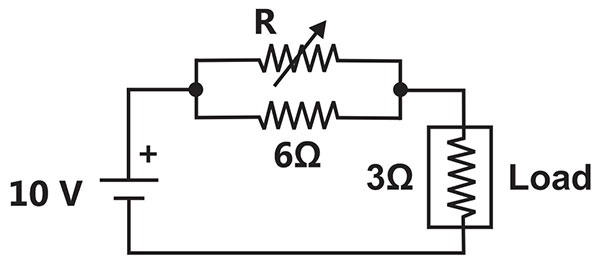
Zero

Infinity
Explanation Locked!
Unlock this branch to view the explanation, track, bookmark and more.
Sign in to UnlockA dual trace oscilloscope is set to operate in the alternate mode. The control input of the multiplexer used in the y-circuit is fed with a signal having a frequency equal to
Explanation Locked!
Unlock this branch to view the explanation, track, bookmark and more.
Sign in to UnlockThe function has

Explanation Locked!
Unlock this branch to view the explanation, track, bookmark and more.
Sign in to UnlockA two-loop position control system is shown below.
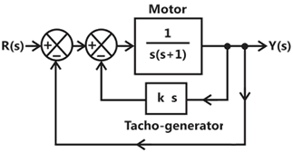
The gain k of the Tacho-generator influences mainly the
Peak overshoot
Natural frequency of oscillations
Phase shift of the closed loop transfer function at very low frequencies

Phase shift of the closed loop transfer function at very high frequencies

Explanation Locked!
Unlock this branch to view the explanation, track, bookmark and more.
Sign in to Unlocktwo-bit counter circuit is shown below.
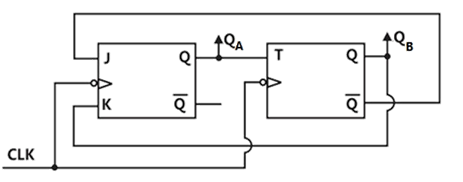
If the state of the counter at the clock time is “10” then the state of the counter at (after three clock cycles) will be


Explanation Locked!
Unlock this branch to view the explanation, track, bookmark and more.
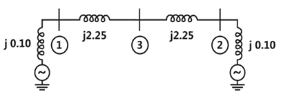
Sign in to UnlockA three-bus network is shown in the figure below indicating the p.u. impedance of each element.
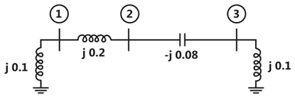
The Bus admittance matrix, Y-bus, of the network is


Explanation Locked!
Unlock this branch to view the explanation, track, bookmark and more.
Sign in to UnlockThe two vectors [1, 1, 1] and , where , are


Explanation Locked!
Unlock this branch to view the explanation, track, bookmark and more.
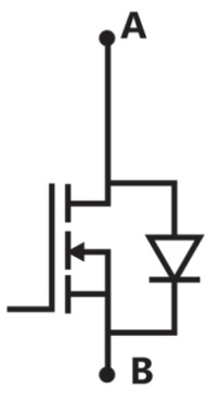
Sign in to UnlockA three-phase current source inverter used for the speed control of an induction motor is to be realized using MOSFET switches as shown below, Switches to are identical switches.


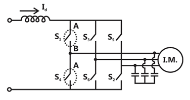
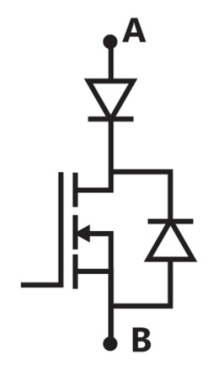
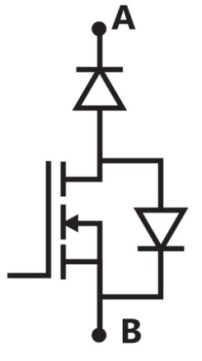
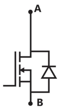
The proper configuration for realizing switches to is
Explanation Locked!
Unlock this branch to view the explanation, track, bookmark and more.
Sign in to UnlockAn open loop system represented by the transfer function is

Explanation Locked!
Unlock this branch to view the explanation, track, bookmark and more.
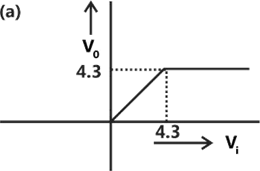
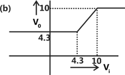
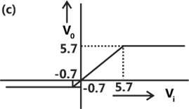
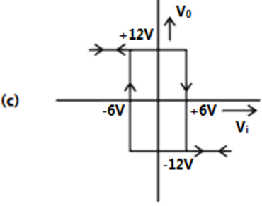
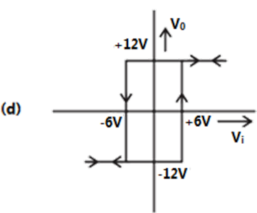
Sign in to UnlockA clipper circuit shown below
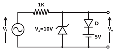
Assuming forward voltage drops of the diodes to be 0.7V, the input-output transfer characteristics of the circuit is
Explanation Locked!
Unlock this branch to view the explanation, track, bookmark and more.
Sign in to UnlockA voltage commutated chopper circuit, operated at 500Hz, is shown below
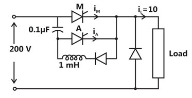
If the maximum value of load current is 10A, then the maximum current through the main (M) and auxiliary (A) thyristor will be


Explanation Locked!
Unlock this branch to view the explanation, track, bookmark and more.
Sign in to UnlockA portion of the main program to call a subroutine SUB in an 8085 environment is given below.
:
:
LXI D, DISP
LP. CALL SUB
:
:
It is desired that control be returned to LP + DISP + 3 when the RET instruction is executed in thee subroutine. The set of instructions that precede the RET instruction in the subroutine are


Explanation Locked!
Unlock this branch to view the explanation, track, bookmark and more.
Sign in to UnlockA capacitor is made with a polymeric dielectric having an of 2.26 and a dielectric breakdown strength of 50kV/cm. The permittivity of free space is 8.85pF/m. If the rectangular plates of the capacitor have a width of 20cm and a length of 40cm, then the maximum electric charge in the capacitor is


Explanation Locked!
Unlock this branch to view the explanation, track, bookmark and more.
Sign in to UnlockThe transistor used in the circuit shown below has a of 30 and is negligible.


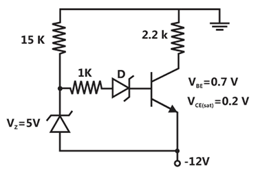
If the forward voltage drop of diode is 0.7V, then the current through collector will be
Explanation Locked!
Unlock this branch to view the explanation, track, bookmark and more.
Sign in to UnlockThe frequency response of a linear system is provided in the tabular form below

1.3 | 1.2 | 1.0 | 0.8 | 0.5 | 0.3 | ||
-130° | -140° | -150° | -160° | -180° | -200° |


The gain margin and phase margin of the system are
6dB and

6dB and

–6dB and
-6dB and
Explanation Locked!
Unlock this branch to view the explanation, track, bookmark and more.
Sign in to UnlockThe matrix is decomposed into a product of a lower triangular matrix [L] and an upper triangular matrix [U]. The properly decomposed [L] and [U] matrices respectively are


Explanation Locked!
Unlock this branch to view the explanation, track, bookmark and more.
Sign in to UnlockA negative sequence relay is commonly used to protect
Explanation Locked!
Unlock this branch to view the explanation, track, bookmark and more.
Sign in to UnlockCircuit turn-off time of an SCR is defined as the time
Explanation Locked!
Unlock this branch to view the explanation, track, bookmark and more.
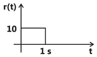
Sign in to UnlockThe steady state error of a unity feedback linear system for a unit step input is 0.1. The steady state error of the same system, for a pulse input r(t) having a magnitude of 10 and a duration of one second, as shown in the figure is
Explanation Locked!
Unlock this branch to view the explanation, track, bookmark and more.
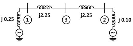
Sign in to UnlockTwo generator units G1 and G2 are connected by 15kV line with a bus at the mid-point as shown below.
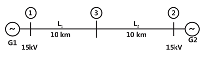
G1 = 250MVA, 15kV, positive sequence reactance X = 25% on its own base G2 = 100MVA, 15kV, positive sequence reactance X for the line = 0.225


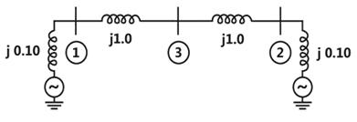
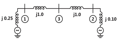
For the above system, the positive sequence diagram with the p.u. values of the 100MVA common base is
Explanation Locked!
Unlock this branch to view the explanation, track, bookmark and more.
Sign in to UnlockTwo generator units G1 and G2 are connected by 15kV line with a bus at the mid-point as shown below.
G1 = 250MVA, 15kV, positive sequence reactance X = 25% on its own base G2 = 100MVA, 15kV, positive sequence reactance X for the line = 0.225
In the above system, the three-phase fault MVA at the bus 3 is
Explanation Locked!
Unlock this branch to view the explanation, track, bookmark and more.
Sign in to UnlockThe RMS value of the current i(t) in the circuit shown below is
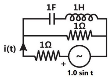


1A

Explanation Locked!
Unlock this branch to view the explanation, track, bookmark and more.
Sign in to UnlockThe voltage applied to a circuit is volts and the circuit draws a current of amperes. Taking the voltage as the reference phasor, the phasor representation of the current in amperes is


Explanation Locked!
Unlock this branch to view the explanation, track, bookmark and more.
Sign in to UnlockThe input voltage given to a converter is

The current drawn by the converter is

The input power factor of the converter is
Explanation Locked!
Unlock this branch to view the explanation, track, bookmark and more.
Sign in to UnlockAn RLC circuit with relevant data is given below.
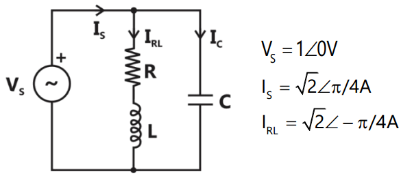
The power dissipated in the resistor R is
0.5W
1W

2W
Explanation Locked!
Unlock this branch to view the explanation, track, bookmark and more.
Sign in to UnlockThe input voltage given to a converter is
The current drawn by the converter is
The active power drawn by the converter is
Explanation Locked!
Unlock this branch to view the explanation, track, bookmark and more.
Sign in to UnlockAn RLC circuit with relevant data is given below.
The current in the figure above is

–j 2A


+j2 A
Explanation Locked!
Unlock this branch to view the explanation, track, bookmark and more.
Sign in to UnlockA solar energy installation utilizes a three-phase bidge converter to feed energy into power system through a transformer of 400V/400V, as shown below.
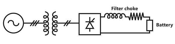
The energy is collected in a bank of 400V batteries and is connected to converter through a large filter choke of resistance.

The maximum current through the battery will be
Explanation Locked!
Unlock this branch to view the explanation, track, bookmark and more.
Sign in to UnlockA solar energy installation utilizes a three-phase bidge converter to feed energy into power system through a transformer of 400V/400V, as shown below.
The energy is collected in a bank of 400V batteries and is connected to converter through a large filter choke of resistance.
The kVA rating of the input transformer is
Explanation Locked!
Unlock this branch to view the explanation, track, bookmark and more.
Sign in to UnlockA low-pass filter with a cut-off frequency of 30Hz is cascaded with a high-pass filter with a cut-off frequency of 20Hz. The resultant system of filters will function as
Explanation Locked!
Unlock this branch to view the explanation, track, bookmark and more.
Sign in to UnlockA 4-point starter is used to start and control the speed of a
Explanation Locked!
Unlock this branch to view the explanation, track, bookmark and more.
Sign in to UnlockConsider the following statements:
(i) The compensating coil of a low power factor wattmeter compensates the effect of the impedance of the current coil.
(ii) The compensating coil of a low power factor wattmeter compensates the effect of the impedance of the voltage coil circuit.
Explanation Locked!
Unlock this branch to view the explanation, track, bookmark and more.
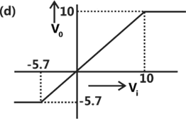
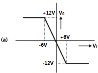
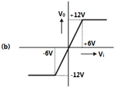
Sign in to UnlockFor the circuit shown below,
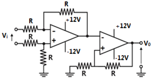
The correct transfer characteristics is
Explanation Locked!
Unlock this branch to view the explanation, track, bookmark and more.
Sign in to UnlockA 220V, DC shunt motor is operating at a speed of 1440 rpm. The armature resistance is and armature current is 10A. If the excitation of the machine is reduced by 10%, the extra resistance to be put in the armature circuit to maintain the same speed and torque will be


Explanation Locked!
Unlock this branch to view the explanation, track, bookmark and more.
Sign in to UnlockA three-phase, salient pole synchronous motor is connected to an infinite bus. It is operated at no load at normal excitation. The field excitation of the motor is first reduced to zero and then increased in the reverse direction gradually. Then the armature current
Explanation Locked!
Unlock this branch to view the explanation, track, bookmark and more.
Sign in to UnlockThe direct axis and quadrature axis reactance of a salient pole alternator are 1.2p.u. and 1.0 p.u. respectively. The armature resistance is negligible. If this alternator is delivering rated kVA at upf and at rated voltage then its power angle is


Explanation Locked!
Unlock this branch to view the explanation, track, bookmark and more.
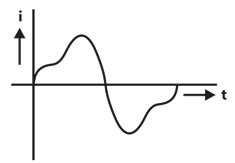
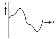
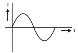
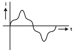
Sign in to UnlockA single-phase air core transformer, fed from a rated sinusoidal supply, is operating at no load. The steady state magnetizing current drawn by the transformer from the supply will have the waveform
Explanation Locked!
Unlock this branch to view the explanation, track, bookmark and more.
Sign in to UnlockA three-phase 440V, 6pole, 50Hz, squirrel cage induction motor is running at a slip of 5%. The speed of stator magnetic field with respect to rotor magnetic field and speed of rotor with respect to state magnetic field are
Explanation Locked!
Unlock this branch to view the explanation, track, bookmark and more.
Sign in to UnlockA nuclear power station of 500MW capacity is located at 300km away from a load center. Select the most suitable power evacuation transmission configuration among the following options


Explanation Locked!
Unlock this branch to view the explanation, track, bookmark and more.
Sign in to UnlockFor enhancing the power transmission in a long EHV transmission line, the most preferred method is to connect a
Explanation Locked!
Unlock this branch to view the explanation, track, bookmark and more.
Sign in to Unlock