
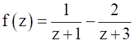
If , then the value of is


x
1
Explanation Locked!
Unlock this branch to view the explanation, track, bookmark and more.
Sign in to UnlockGiven. If C is a counter clockwise path in the z-plane such that, the value of is

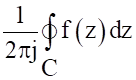
Explanation Locked!
Unlock this branch to view the explanation, track, bookmark and more.
Sign in to UnlockThe Fourier transform of a signal h(t) is . The value of h(0) is


1
2
Explanation Locked!
Unlock this branch to view the explanation, track, bookmark and more.
Sign in to UnlockWith initial condition x(1) = 0.5, the solution of the differential equation is


Explanation Locked!
Unlock this branch to view the explanation, track, bookmark and more.
Sign in to UnlockConsider the differential equation
with

and


The numerical value of is

Explanation Locked!
Unlock this branch to view the explanation, track, bookmark and more.
Sign in to UnlockTwo independent random variables X and Y are uniformly distributed in the interval [-1, 1]. The probability that max [X, Y] is less than ½ is
Explanation Locked!
Unlock this branch to view the explanation, track, bookmark and more.
Sign in to UnlockThe figure shows a two-generator system supplying a load of, connected at bus 2.

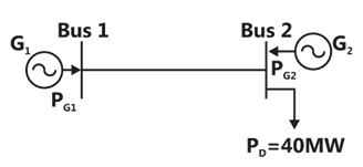
The fuel cost of generators and are:


and and he loss in the line is, where the loss coefficient is specified in p.u on a 100MVA base. The most economic power generation schedule in MW is


Explanation Locked!
Unlock this branch to view the explanation, track, bookmark and more.
Sign in to UnlockA fair coin is tossed till a head appears for the first time. The probability that the number of required tosses is odd, is
Explanation Locked!
Unlock this branch to view the explanation, track, bookmark and more.
Sign in to UnlockThe transfer function of a compensator is given as

is a lead compensator if

Explanation Locked!
Unlock this branch to view the explanation, track, bookmark and more.
Sign in to UnlockThe transfer function of a compensator is given as
The phase of the above lead compensator is maximum at


Explanation Locked!
Unlock this branch to view the explanation, track, bookmark and more.
Sign in to UnlockIf , then the region of convergence (ROC) of its Z-transform in the Z-plane will be


Explanation Locked!
Unlock this branch to view the explanation, track, bookmark and more.
Sign in to UnlockThe unilateral Laplace transform of f(t) is . The unilateral Laplace transform of t f(t) is


Explanation Locked!
Unlock this branch to view the explanation, track, bookmark and more.
Sign in to UnlockThe bridge method commonly used for finding mutual inductance is
Explanation Locked!
Unlock this branch to view the explanation, track, bookmark and more.
Sign in to UnlockLet y[n] denote the convolution of h[n] and g[n], where and g[n] is a casual sequence. If and , then g[1] equals


0

1
3/2
Explanation Locked!
Unlock this branch to view the explanation, track, bookmark and more.
Sign in to UnlockThe input x(t) and output y(t) of a system are related as. The system is

Explanation Locked!
Unlock this branch to view the explanation, track, bookmark and more.
Sign in to UnlockIn the sum of products function, the prime implicant’s are


Explanation Locked!
Unlock this branch to view the explanation, track, bookmark and more.
Sign in to UnlockThe impedance looking into nodes 1 and 2 in the given circuit is
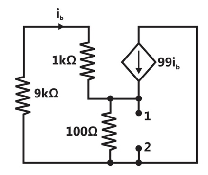


Explanation Locked!
Unlock this branch to view the explanation, track, bookmark and more.
Sign in to UnlockThe output Y of a 2-bit comparator is logic 1 whenever the 2-bit input A is greater than the 2-bit input B. The number of combinations for which the output is logic 1, is
Explanation Locked!
Unlock this branch to view the explanation, track, bookmark and more.
Sign in to UnlockWith 10V dc connected at port A in the linear nonreciprocal two-port network shown below, the following were observed:
(i) connected at port B draws a current of 3A

(ii) connected at port B draws a current of 2A

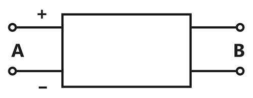
For the same network, with 6V dc connected at port A, connected at port B draws 7/3A. If 8V dc connected to port A, the open circuit voltage at port B is
Explanation Locked!
Unlock this branch to view the explanation, track, bookmark and more.
Sign in to UnlockConsider the given circuit,
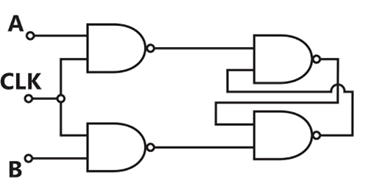
In this circuit, the race around
Explanation Locked!
Unlock this branch to view the explanation, track, bookmark and more.
Sign in to UnlockThe maximum value of in the interval [1, 6] is

Explanation Locked!
Unlock this branch to view the explanation, track, bookmark and more.
Sign in to UnlockThe bus admittance matrix of a three-bus three-line system is

If each transmission line between the two buses is represented by an equivalent -network, the magnitude of the shunt susceptance of the line connecting bus 1 and 2 is

Explanation Locked!
Unlock this branch to view the explanation, track, bookmark and more.
Sign in to UnlockWith 10V dc connected at port A in the linear nonreciprocal two-port network shown below, the following were observed:
(i) connected at port B draws a current of 3A
(ii) connected at port B draws a current of 2A
With 10V dc connected at port A, the current drawn by connected at port B is

Explanation Locked!
Unlock this branch to view the explanation, track, bookmark and more.
Sign in to UnlockThe state transition diagram for the logic circuit shown is
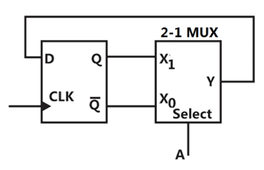
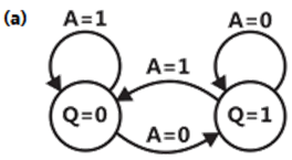
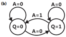
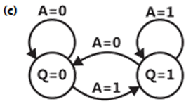
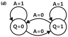
Explanation Locked!
Unlock this branch to view the explanation, track, bookmark and more.
Sign in to UnlockIn the 3-phase inverter circuit shown, the load is balanced and the gating scheme is conduction mode. All the switching devices are ideal.

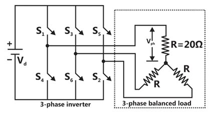
The RMS value of load phase voltage is
Explanation Locked!
Unlock this branch to view the explanation, track, bookmark and more.
Sign in to UnlockThe feedback system shown below oscillates at 2rad/s when
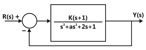
Explanation Locked!
Unlock this branch to view the explanation, track, bookmark and more.
Sign in to UnlockThe i-v characteristics of the diode in the circuit given below are
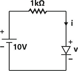

The current in the circuit is
Explanation Locked!
Unlock this branch to view the explanation, track, bookmark and more.
Sign in to UnlockIn the 3-phase inverter circuit shown, the load is balanced and the gating scheme is conduction mode. All the switching devices are ideal.
If the dc bus voltage, the power consumed by 3-phase load is

Explanation Locked!
Unlock this branch to view the explanation, track, bookmark and more.
Sign in to UnlockA cylindrical rotor generator delivers 0.5pu power in the steady state to an infinite bus through a transmission line of reactance 0.5pu. The generator no-load voltage is 1.5pu and the infinite bus voltage is 1pu. The inertia constant of the generator is 5 MW-s/MVA and the generator reactance is 1pu. The critical clearing angle, in degrees, for a three-phase dead short circuit fault at the generator terminal is
Explanation Locked!
Unlock this branch to view the explanation, track, bookmark and more.
Sign in to UnlockIn the circuit shown, an ideal switch S is operated at 100kHz with a duty ratio of 50%. Given that is 1.6A peak-to-peak and is 5 A dc, the peak current in S is


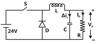
Explanation Locked!
Unlock this branch to view the explanation, track, bookmark and more.
Sign in to UnlockThe state variable description of an LTI system is given by


Where y is the output and u is the input. The system is controllable for


Explanation Locked!
Unlock this branch to view the explanation, track, bookmark and more.
Sign in to UnlockThe voltage gain of the circuit shown below is

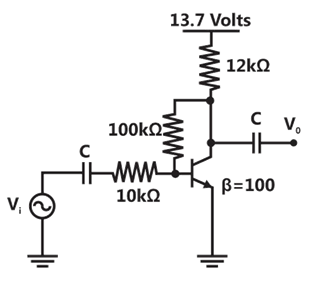


Explanation Locked!
Unlock this branch to view the explanation, track, bookmark and more.
Sign in to UnlockThe direction of vector A is radially outward from the oigin, with where and k is a constant. The value of n for which is


Explanation Locked!
Unlock this branch to view the explanation, track, bookmark and more.
Sign in to UnlockIn the following figure, and are ideal capacitors. has been charged to 12V before the ideal switch S is closed at t = 0. The current i(t) for all t is


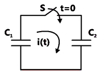
Explanation Locked!
Unlock this branch to view the explanation, track, bookmark and more.
Sign in to UnlockA system with transfer function
is excited by . The steady state output of the system is zero at


Explanation Locked!
Unlock this branch to view the explanation, track, bookmark and more.
Sign in to UnlockIf , then is


Explanation Locked!
Unlock this branch to view the explanation, track, bookmark and more.
Sign in to UnlockGiven that
and , the value of is


Explanation Locked!
Unlock this branch to view the explanation, track, bookmark and more.
Sign in to UnlockThe typical ratio of latching current to holding current in a 20A thyristor is
Explanation Locked!
Unlock this branch to view the explanation, track, bookmark and more.
Sign in to UnlockThe sequence components of the fault current are as follows: . The type of fault in the system is

Explanation Locked!
Unlock this branch to view the explanation, track, bookmark and more.
Sign in to UnlockIn the circuit shown below, the current through the inductor is
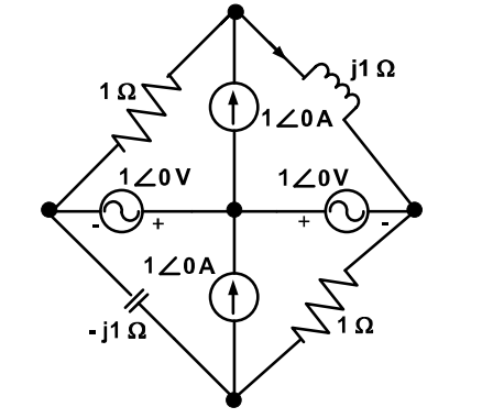


0 A
Explanation Locked!
Unlock this branch to view the explanation, track, bookmark and more.
Sign in to UnlockThe average power delivered to an impedance (4–j3) by a current is


Explanation Locked!
Unlock this branch to view the explanation, track, bookmark and more.
Sign in to UnlockAssuming both the voltage sources are in phase, the value of R for which maximum power is transferred from circuit A to circuit B is
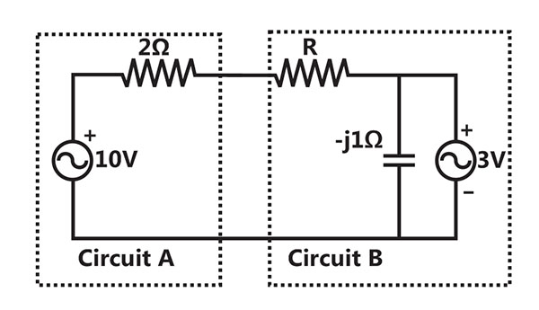


Explanation Locked!
Unlock this branch to view the explanation, track, bookmark and more.
Sign in to UnlockA half-controlled single-phase bridge rectifier is supplying an R-L load. It is operated at a firing angle and the load current is continuous. The fraction of cycle that the freewheeling diode conducts is

1/2


Explanation Locked!
Unlock this branch to view the explanation, track, bookmark and more.
Sign in to Unlock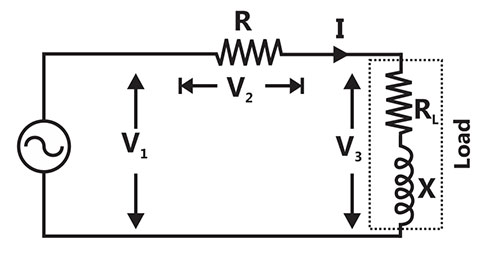
In the circuit shown, the three voltmeter readings are .

The power factor of the load is
Explanation Locked!
Unlock this branch to view the explanation, track, bookmark and more.
Sign in to UnlockIn the circuit shown, the three voltmeter readings are .
If , the approximate power consumption in the load is

Explanation Locked!
Unlock this branch to view the explanation, track, bookmark and more.
Sign in to UnlockThe circuit shown is a
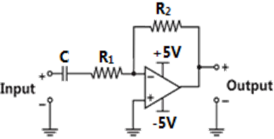
Low pass filter with

High pass filter with

Low pass filter with
High pass filter with
Explanation Locked!
Unlock this branch to view the explanation, track, bookmark and more.
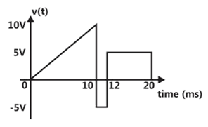
Sign in to UnlockA periodic voltage waveform observed on an oscilloscope across a load is shown. A permanent magnet moving coil (PMMC) meter connected across the same load reads
Explanation Locked!
Unlock this branch to view the explanation, track, bookmark and more.
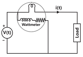
Sign in to UnlockFor the circuit shown in the figure, the voltage and current expression are and


The average power measured by the wattmeter is


Explanation Locked!
Unlock this branch to view the explanation, track, bookmark and more.
Sign in to UnlockA 220V, 15kW, 1000rpm shunt motor with armature resistance of , has a rated line current of 68A and a rated field of 2.2A. The change in field flux required to obtain a speed of 1600 rpm while drawing a line current of 52.8 A and a field current of 1.8A is a

Explanation Locked!
Unlock this branch to view the explanation, track, bookmark and more.
Sign in to UnlockAn analog voltmeter uses external multiplier settings. With a multiplier setting of, it reads 440V and with a multiplier setting of, it reads 352V. For a multiplier setting of, the voltmeter reads


Explanation Locked!
Unlock this branch to view the explanation, track, bookmark and more.
Sign in to UnlockA single phase 10kVA, 50Hz transformer with 1kV primary winding draws 0.5A and 55W, at rated voltage and frequency, on no load. A second transformer has a core with all its linear dimensions times the corresponding dimensions of the first transformer. The core material and lamination thickness are the same in both transformers. The primary windings of both the transformers have the same number of turns. If a rated voltage of 2kV at 50Hz is applied to the primary of the second transformer, then the no load current and power, respectively, are

Explanation Locked!
Unlock this branch to view the explanation, track, bookmark and more.
Sign in to UnlockThe slip of an induction motor normally does not depend on
Explanation Locked!
Unlock this branch to view the explanation, track, bookmark and more.
Sign in to UnlockA two-phase load draws the following phase currents: , . These currents are balanced if is equal to


Explanation Locked!
Unlock this branch to view the explanation, track, bookmark and more.
Sign in to UnlockThe locked rotor current in a 3-phase, star connected 15kW, 4-pole, 230V, 50Hz induction motor at rated conditions is 50A. Neglecting losses and magnetizing current, the approximate blocked rotor line current drawn when the motor is connected to a 236V, 57Hz supply is
Explanation Locked!
Unlock this branch to view the explanation, track, bookmark and more.
Sign in to UnlockFor the system shown below, and are complex power demands at bus 1 and bus 2 respectively. If , the VAR rating of the capacitor connected at bus 2 is


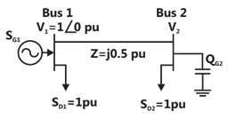
Explanation Locked!
Unlock this branch to view the explanation, track, bookmark and more.
Sign in to Unlock