
A band-limited signal with a maximum frequency of 5 kHz is to be sampled. According to the sampling theorem, the sampling frequency in kHz which is not valid is
Explanation Locked!
Unlock this branch to view the explanation, track, bookmark and more.
Sign in to UnlockSquare roots of –i, where

i, –i


Explanation Locked!
Unlock this branch to view the explanation, track, bookmark and more.
Sign in to UnlockEvaluated anticlockwise around the circle, where i =, is


Explanation Locked!
Unlock this branch to view the explanation, track, bookmark and more.
Sign in to UnlockIn the circuit shown below, Q1 has negligible collector-to-emitter saturation voltage and the diode drops negligible voltage across it under forward bias. If Vcc. is +5 V, X and Y are digital signals with 0 V as logic 0 and Vcc. as logic 1, then the Boolean expression for Z is
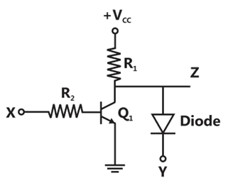
X Y


Explanation Locked!
Unlock this branch to view the explanation, track, bookmark and more.
Sign in to UnlockWhen the Newton-Raphson method is applied to solve the equation, the solution at the end of the first iteration with the initial guess value as is


Explanation Locked!
Unlock this branch to view the explanation, track, bookmark and more.
Sign in to UnlockA continuous random variable has a probability density function. Then P is


Explanation Locked!
Unlock this branch to view the explanation, track, bookmark and more.
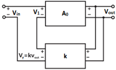
Sign in to UnlockIn the feedback network shown below, if the feedback factor k is increased, then the
Explanation Locked!
Unlock this branch to view the explanation, track, bookmark and more.
Sign in to UnlockA bulb in a staircase has two switches, one switch being at the ground floor and the other one at the first floor. The bulb can be turned ON and also can be turned OFF by any one of the switches irrespective of the state of the other switch. The logic of switching of the bulb resembles
Explanation Locked!
Unlock this branch to view the explanation, track, bookmark and more.
Sign in to UnlockThe impulse response of a system is h(t)=t u(t) . for an input u(t-1), the output is


Explanation Locked!
Unlock this branch to view the explanation, track, bookmark and more.
Sign in to UnlockThe impulse response of a continuous time system is given by h(t)=δ(t-1)+δ(t-3). The value of the step response at t=2 is
Explanation Locked!
Unlock this branch to view the explanation, track, bookmark and more.
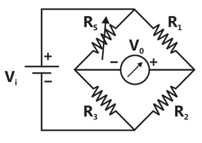
Sign in to UnlockA strain gauge forms one arm of the bridge shown in the figure below and has a nominal resistance without any load as Other bridge resistances are. The maximum permissible current through the strain gauge is 20mA. During certain measurement when the bridge is excited by maximum permissible voltage and the strain gauge resistance is increased by 1% over the nominal value, the output voltage V₀ in mV is


Explanation Locked!
Unlock this branch to view the explanation, track, bookmark and more.
Sign in to UnlockWhich one of the following statements is NOT TRUE for a continuous time causal and stable LTI system?
All the poles of the system must lie on the left side of the axis.

Zeros of the system can lie anywhere in the s-plane.
All the poles must lie within |s|=1.
All the roots of the characteristic equation must be located on the left side of the jw axis.
Explanation Locked!
Unlock this branch to view the explanation, track, bookmark and more.
Sign in to UnlockFor a periodic signal
, the fundamental frequency in rad/s is

Explanation Locked!
Unlock this branch to view the explanation, track, bookmark and more.
Sign in to UnlockTwo systems with impulse responses and are connected in cascade. Then the overall impulse response of the cascaded system is given by


Product of and
Sum of and
Convolution of and
Subtraction of from
Explanation Locked!
Unlock this branch to view the explanation, track, bookmark and more.
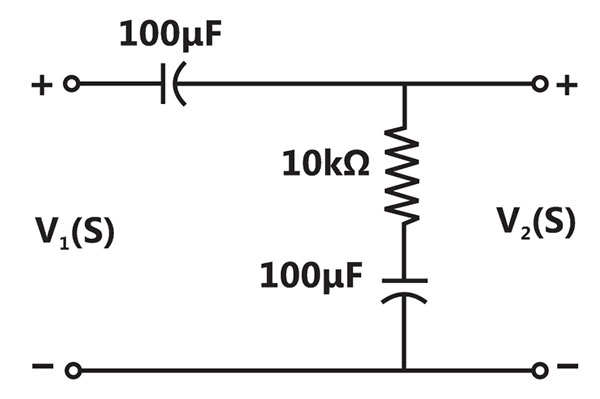
Sign in to UnlockThe transfer function of the circuit shown below is


Explanation Locked!
Unlock this branch to view the explanation, track, bookmark and more.
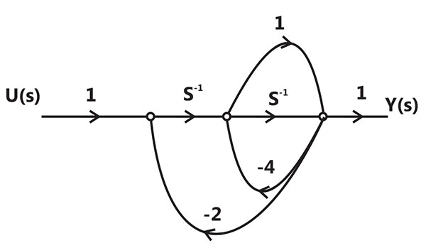
Sign in to UnlockThe signal flow graph for a system is given below. The transfer function for this system is


Explanation Locked!
Unlock this branch to view the explanation, track, bookmark and more.
Sign in to UnlockThe clock frequency applied to the digital circuit shown in the figure below is 1 kHz. If the initial state of the output Q of the flip-flop is 0, then the frequency of the output waveform Q in kHz is

Explanation Locked!
Unlock this branch to view the explanation, track, bookmark and more.
Sign in to UnlockA source has an internal impedance of . If a purely resistive load connected to this source has to extract the maximum power out of the source, its value in Ω should beA source has an internal impedance of . If a purely resistive load connected to this source has to extract the maximum power out of the source, its value in Ω should be


Explanation Locked!
Unlock this branch to view the explanation, track, bookmark and more.
Sign in to UnlockFor a power system network with n nodes, of its bus impedance matrix is j0.5 per unit. The voltage at node 3 is per unit. If a capacitor having reactance of –j3.5 per unit is now added to the network between node 3 and the reference node, the current drawn by the capacitor per unit is


Explanation Locked!
Unlock this branch to view the explanation, track, bookmark and more.
Sign in to UnlockThe curl of the gradient of the scalar field defined by is


0
Explanation Locked!
Unlock this branch to view the explanation, track, bookmark and more.
Sign in to UnlockIn the following network, the voltage magnitudes at all buses are equal to 1 p.u., the voltage phase angles are very small, and the line resistances are negligible. All the line reactances are equal to j1 Ω.
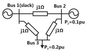
The voltage phase angles in rad at buses 2 and 3 are


Explanation Locked!
Unlock this branch to view the explanation, track, bookmark and more.
Sign in to UnlockThe Voltage Source Inverter (VSI) shown in the figure below is switched to provide a 50 Hz, square-wave ac output voltage (V₀) across an R-L load. Reference polarity of V₀ and reference direction of the output current i₀ are indicated in the figure. It is given that R=3Ω, L=9.55mH.
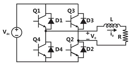
In the interval when V₀<0 and i₀>0 the pair of devices which conducts the load current is
Explanation Locked!
Unlock this branch to view the explanation, track, bookmark and more.
Sign in to UnlockGiven a vector field , the line integral ∫F.dl evaluated along a segment on the x-axis from x=1 to x=2 is

Explanation Locked!
Unlock this branch to view the explanation, track, bookmark and more.
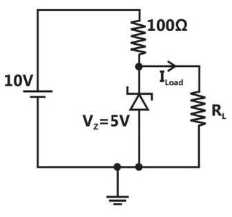
Sign in to UnlockIn the circuit shown below, the knee current of the ideal Zener diode is 10mA. To maintain 5 V across , in Ω and the minimum power rating of the Zener diode in mW respectively are

Explanation Locked!
Unlock this branch to view the explanation, track, bookmark and more.
Sign in to UnlockIn the following network, the voltage magnitudes at all buses are equal to 1 p.u., the voltage phase angles are very small, and the line resistances are negligible. All the line reactances are equal to j1 Ω.
If the base impedance and the line-to-line base voltage are 100 Ω and 100kV, respectively, then the real power in MW delivered by the generator connected at the slack bus is
Explanation Locked!
Unlock this branch to view the explanation, track, bookmark and more.
Sign in to UnlockA function is defined over an open interval x= (1, 2). At least at one point in this interval, is exactly


Explanation Locked!
Unlock this branch to view the explanation, track, bookmark and more.
Sign in to UnlockThe Voltage Source Inverter (VSI) shown in the figure below is switched to provide a 50 Hz, square-wave ac output voltage (V₀) across an R-L load. Reference polarity of V₀ and reference direction of the output current i₀ are indicated in the figure. It is given that R=3Ω, L=9.55mH.
Appropriate transition i.e., Zero Voltage Switching (ZVS) /Zero Current Switching (ZCS) of the IGBTs during turn-on/turn-off is
Explanation Locked!
Unlock this branch to view the explanation, track, bookmark and more.
Sign in to UnlockThe flux density at a point in space is given by. The value of constant k must be equal to

Explanation Locked!
Unlock this branch to view the explanation, track, bookmark and more.
Sign in to UnlockThe angle δ in the swing equation of a synchronous generator is the
Explanation Locked!
Unlock this branch to view the explanation, track, bookmark and more.
Sign in to UnlockThe state variable formulation of a system is given as
, , and


The system is
Explanation Locked!
Unlock this branch to view the explanation, track, bookmark and more.
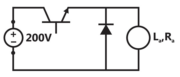
Sign in to UnlockThe separately excited dc motor in the figure below has a rated armature current of 20A and a rated armature voltage of 150 V. An ideal chopper switching at 5 kHz is used to control the armature voltage. If , , neglecting armature reaction, the duty ratio of the chopper to obtain 50% of the rated torque at the rated speed and the rated field current is


Explanation Locked!
Unlock this branch to view the explanation, track, bookmark and more.
Sign in to UnlockThe state variable formulation of a system is given as
, , and
The response y (t) to a unit step input is


Explanation Locked!
Unlock this branch to view the explanation, track, bookmark and more.
Sign in to UnlockIn the figure shown below, the chopper feeds a resistive load from a battery source. MOSFET Q is switched at 250 kHz, with a duty ratio of 0.4. All elements of the circuit are assumed to be ideal.
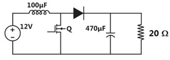
The average source current in Amps in steady-state is
Explanation Locked!
Unlock this branch to view the explanation, track, bookmark and more.
Sign in to UnlockIn the figure shown below, the chopper feeds a resistive load from a battery source. MOSFET Q is switched at 250 kHz, with a duty ratio of 0.4. All elements of the circuit are assumed to be ideal.
The PEAK-TO-PEAK source current ripple in Amps is
Explanation Locked!
Unlock this branch to view the explanation, track, bookmark and more.
Sign in to UnlockThree capacitors , , and , whose values are 10μF, 5μF, and 2μF respectively, have breakdown voltages of 10V, 5V, and 2V respectively. For the interconnection shown, the maximum safe voltage in volts that can be applied across the combination and the corresponding total charge in μC stored in the effective capacitance across the terminals are respectively


Explanation Locked!
Unlock this branch to view the explanation, track, bookmark and more.
Sign in to UnlockA dielectric slab with 500mm × 500mm cross –section is 0.4m long. The slab is subjected to a uniform electric field of. is equal to 2. The value of constant is . The energy stored n the dielectric in joules is


88.5
885
Explanation Locked!
Unlock this branch to view the explanation, track, bookmark and more.
Sign in to UnlockThe Bode plot of a transfer function G(s) is shown in the figure below.
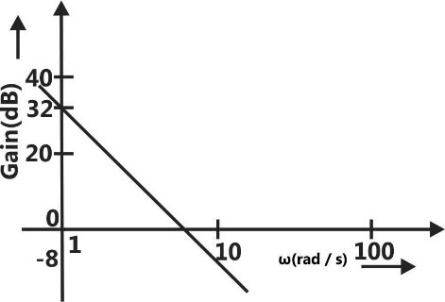
The gain (20log|G(s)|) is 32 dB and -8 dB at 1rad/s and 10rad/s respectively. The phase is negative for all ω. Then G(s) is


Explanation Locked!
Unlock this branch to view the explanation, track, bookmark and more.
Sign in to UnlockConsider a delta connection of resistors and its equivalent star connection as shown below. If all elements of the delta connection are scaled by a factor k, k>0, the element of the corresponding star equivalent will be scaled by a factor of
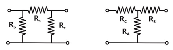

k
1/k

Explanation Locked!
Unlock this branch to view the explanation, track, bookmark and more.
Sign in to UnlockThe equation has

No solution
Only one solution

Non-zero unique solution
Multiple solutions
Explanation Locked!
Unlock this branch to view the explanation, track, bookmark and more.
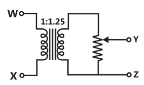
Sign in to UnlockA voltage Volts is applied across YZ. Assuming ideal diodes, the voltage measured across WX in Volts, is

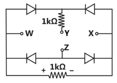


0 for all t
Explanation Locked!
Unlock this branch to view the explanation, track, bookmark and more.
Sign in to UnlockA matrix has Eigen values –1 and -2. The corresponding eigenvectors are and respectively. The matrix is


Explanation Locked!
Unlock this branch to view the explanation, track, bookmark and more.
Sign in to UnlockAssuming zero initial condition, the response y(t) of the system given below to a unit step input u(t) is
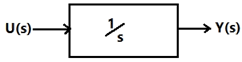
u(t)
t u(t)


Explanation Locked!
Unlock this branch to view the explanation, track, bookmark and more.
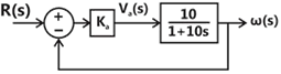
Sign in to UnlockThe open-loop transfer function of a dc motor is given as. When connected in feedback as shown below, the approximate value of that will reduce the time constant of the closed loop system by one hundred times as compared to that of the open-loop system is


Explanation Locked!
Unlock this branch to view the explanation, track, bookmark and more.
Sign in to UnlockThyristor T in the figure below is initially off and is triggered with a single pulse of width 10μs. It is given that and. Assuming latching and holding currents of the thyristor are both zero and the initial charge on C is zero, T conducts for


Explanation Locked!
Unlock this branch to view the explanation, track, bookmark and more.
Sign in to UnlockA single-phase load is supplied by a single –phase voltage source. If the current flowing from the Load to the source is and if the voltage at the load terminals is , then the


Explanation Locked!
Unlock this branch to view the explanation, track, bookmark and more.
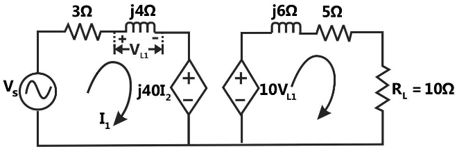
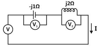
Sign in to UnlockIn the circuit shown below, if the source voltage then the Thevenin’s equivalent voltage in volts as seen by the load resistance is


Explanation Locked!
Unlock this branch to view the explanation, track, bookmark and more.
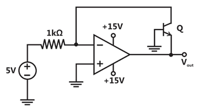
Sign in to UnlockIn the circuit shown below what is the output voltage in Volts if a silicon transistor Q and an ideal op-amp are used?

Explanation Locked!
Unlock this branch to view the explanation, track, bookmark and more.
Sign in to UnlockTwo magnetically uncoupled inductive coils have Q factors and at the chosen operating frequency. Their respective resistances are and . When connected in series, their effective Q factor at the same operating frequency is


Explanation Locked!
Unlock this branch to view the explanation, track, bookmark and more.
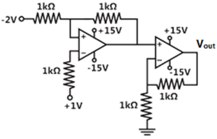
Sign in to UnlockIn the circuit shown below the op-amps are ideal. Then in Volts is

Explanation Locked!
Unlock this branch to view the explanation, track, bookmark and more.
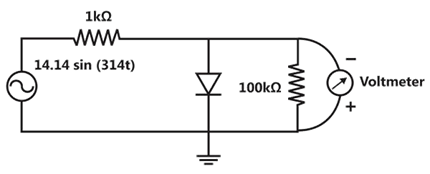
Sign in to UnlockThe input impedance of the permanent magnet moving coil (PMMC) voltmeter is infinite. Assuming that the diode shown in the figure below is ideal, the reading of the voltmeter in volts is
Explanation Locked!
Unlock this branch to view the explanation, track, bookmark and more.
Sign in to UnlockThree moving iron type voltmeters are connected as shown below. Voltmeter readings are V, and , as indicated. The correct relation among the voltmeter readings is


Explanation Locked!
Unlock this branch to view the explanation, track, bookmark and more.
Sign in to UnlockA single-phase transformer has no-load loss of 64W, as obtained from an open-circuit test. When a short-circuit test is performed on it with 90% of the rated currents flowing in its both LV and HV windings, the measured loss is 81W. The transformer has maximum efficiency when operated at
Explanation Locked!
Unlock this branch to view the explanation, track, bookmark and more.
Sign in to UnlockThe following arrangement consists of an ideal transformer and an attenuator which attenuates by a factor of 0.8. An ac voltage is applied across WX to get an open circuit voltage across YZ. Next, an ac voltage is applied across YZ to get an open circuit voltage across WX. Then, are respectively,


Explanation Locked!
Unlock this branch to view the explanation, track, bookmark and more.
Sign in to UnlockLeakage flux in an induction motor is
Explanation Locked!
Unlock this branch to view the explanation, track, bookmark and more.
Sign in to UnlockA 4-pole induction motor, supplied by a slightly unbalanced three-phase 50Hz source, is rotating at 1440rpm. The electrical frequency in Hz of the induced negative sequence current in the rotor is
Explanation Locked!
Unlock this branch to view the explanation, track, bookmark and more.
Sign in to Unlock