
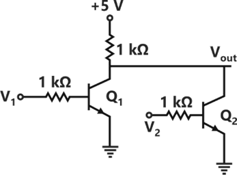
The logical gate implemented using the circuit shown below where, V1 and V2 are inputs (with 0 V as digital 0 and 5 V as digital 1) and VOUT is the output, is
Explanation Locked!
Unlock this branch to view the explanation, track, bookmark and more.
Sign in to UnlockThe following measurements are obtained on a single phase load:
, and . If the power factor is calculated using these measurements, the worst-case error in the calculated power factor in percent is ________. (Given answer up to one decimal place).


Explanation Locked!
Unlock this branch to view the explanation, track, bookmark and more.
Sign in to UnlockFor a complex number

Explanation Locked!
Unlock this branch to view the explanation, track, bookmark and more.
Sign in to UnlockOnly one of the real roots of lies in the interval and bisection method is used to find its value. For achieving an accuracy of 0.001, the required minimum number of iterations is ___________ .


Explanation Locked!
Unlock this branch to view the explanation, track, bookmark and more.
Sign in to UnlockConsider the line integral The line c is shown in the figure below

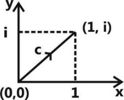
The value of I is


Explanation Locked!
Unlock this branch to view the explanation, track, bookmark and more.
Sign in to UnlockThe Boolean expression simplifies to


Explanation Locked!
Unlock this branch to view the explanation, track, bookmark and more.
Sign in to UnlockTwo passive two-port networks are connected in cascade as shown in figure. A voltage source is connected at port 1
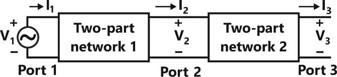
Given,


are the generalized circuit constants. If the Thevenin equivalent circuit at port 3 consists of a voltage source and impedance , connected in series, then


Explanation Locked!
Unlock this branch to view the explanation, track, bookmark and more.
Sign in to UnlockConsider the differential equation . There exists a unique solution for this differential equation when t belongs to the interval

Explanation Locked!
Unlock this branch to view the explanation, track, bookmark and more.
Sign in to UnlockThe slope and level detector circuit in a CRO has a delay of 100 ns. The start-stop sweep generator has a response time of 50 ns. In order to display correctly, a delay line of
Explanation Locked!
Unlock this branch to view the explanation, track, bookmark and more.
Sign in to UnlockLet, where denotes convolution, Let c be a positive real-valued constant. Choose the correct expression for z (ct).


Explanation Locked!
Unlock this branch to view the explanation, track, bookmark and more.
Sign in to UnlockConsider
.
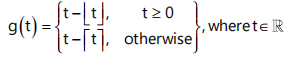
Here, represents the largest integer less than or equal to t and denotes the smallest integer greater than or equal to t. The coefficient of the second harmonic component of the Fourier series representing is ___________


No harmonics can be determined
Explanation Locked!
Unlock this branch to view the explanation, track, bookmark and more.
Sign in to UnlockLet the signal be passed through an LTI system with frequency response , as given in the figure below


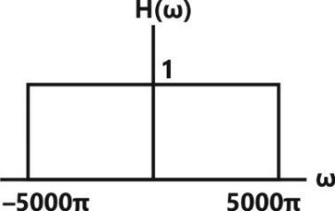
The Fourier series representation of the output is given as


Explanation Locked!
Unlock this branch to view the explanation, track, bookmark and more.
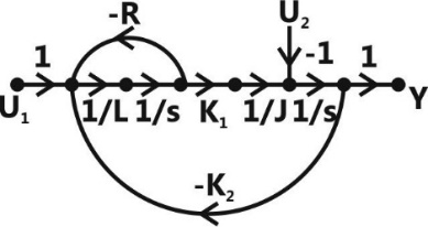
Sign in to UnlockIn the system whose signal flow graph is shown in the figure, are inputs. The transfer function v


Explanation Locked!
Unlock this branch to view the explanation, track, bookmark and more.
Sign in to UnlockConsider the system with following input-output relation

Where x [n] is the input and y [n] is the output. The system is
Explanation Locked!
Unlock this branch to view the explanation, track, bookmark and more.
Sign in to UnlockConsider a causal and stable LTI system with rational transfer function H(z), whose corresponding impulse response begins at n = 0. Furthermore,
. The poles of H (z) are for k = 1, 2, 3, 4.


The zeros of H(z) are all at z = 0. Let . The value of g[8] equals ___________________. (Given the answer up to three decimal places).

Explanation Locked!
Unlock this branch to view the explanation, track, bookmark and more.
Sign in to UnlockFor the circuit shown in the figure below, assume that diodes are ideal.

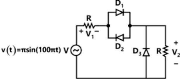
The DC components of voltages, respectively are

Explanation Locked!
Unlock this branch to view the explanation, track, bookmark and more.
Sign in to UnlockLet a causal LTI system be characterized by the following differential equation, with initial rest condition

Where, x(t) and y(t) are the input and output respectively. The impulse response of the system is (u(t) is the unit step function)


Explanation Locked!
Unlock this branch to view the explanation, track, bookmark and more.
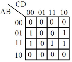
Sign in to UnlockThe output expression for the Karnaugh map shown below is


Explanation Locked!
Unlock this branch to view the explanation, track, bookmark and more.
Sign in to UnlockA closed loop system has the characteristic equation given by . For this system to be stable, which one of the following conditions should be satisfied?


Explanation Locked!
Unlock this branch to view the explanation, track, bookmark and more.
Sign in to UnlockA 10-bus power system consists of four generator buses indexed as G1, G2, G3, G4 and six load buses indexed as L1, L2, L3, L4, L5, L6. The generator-bus G1 is considered as slack bus, and the load buses L3 and L4 are voltage controlled buses. The generator at bus G2 cannot supply the required reactive power demand, and hence it is operating at its maximum reactive power limit. The number of non-linear equations required for solving the load flow problem using Newton-Raphson method in polar form is _____________.
Explanation Locked!
Unlock this branch to view the explanation, track, bookmark and more.
Sign in to UnlockA 3-bus power system is shown in the figure below, where the diagonal elements of Y-bus matrix are:

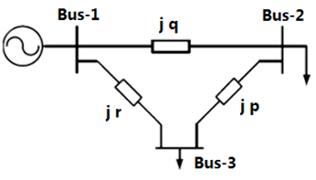
The per unit values of the line reactance’s p, q and shown in the figure are


Explanation Locked!
Unlock this branch to view the explanation, track, bookmark and more.
Sign in to UnlockThe bus admittance matrix for a power system network is

There is a transmission line, connected between buses 1 and 3, which is represented by the circuit shown in figure.

If this transmission line is removed from service, what is the modified bus admittance matrix?


Explanation Locked!
Unlock this branch to view the explanation, track, bookmark and more.
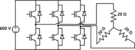
Sign in to UnlockA 3-phase voltage source inverter is supplied from a 600V DC source as shown in the figure below. For a star connected resistive load of per phase, the load power for 120° device conduction, in kW, is ___________.

Explanation Locked!
Unlock this branch to view the explanation, track, bookmark and more.
Sign in to UnlockThe figure shows the single line diagram of a power system with a double circuit transmission line. The expression for electrical power is 1.5 sin , where is the rotor angle. The system is operating at the stable equilibrium point with mechanical power equal to 1 pu. If one of the transmission line circuits is removed, the maximum value of , as the rotor swings, is 1.221 radian. If the expression for electrical power with one transmission line circuit removed is , the value of , in pu is ____________. (Give the answer up to three decimal places)


Explanation Locked!
Unlock this branch to view the explanation, track, bookmark and more.
Sign in to UnlockIn the converter circuit shown below, the switches are controlled such that the load voltage is a 400 Hz square wave.

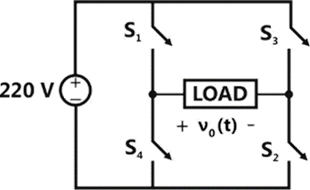
The RMS value of the fundamental component of in volts is ______________.
Explanation Locked!
Unlock this branch to view the explanation, track, bookmark and more.
Sign in to UnlockA solid iron cylinder is place in region containing a uniform magnetic field such that the cylinder axis is parallel to the magnetic field direction. The magnetic field lines inside the cylinder will
Explanation Locked!
Unlock this branch to view the explanation, track, bookmark and more.
Sign in to UnlockThe magnitude of magnetic flux density (B) in micro Teslas (µT), at the center of a loop of wire wound as a regular hexagon of side length 1 m carrying a current (I = 1 A) and placed in vacuum as shown in the figure is _________. (Give the answer up to two decimal places).

Explanation Locked!
Unlock this branch to view the explanation, track, bookmark and more.
Sign in to UnlockThe switch in the figure below was closed for a long time. It is opened at t = 0. The current in the inductor of 2 H for, is

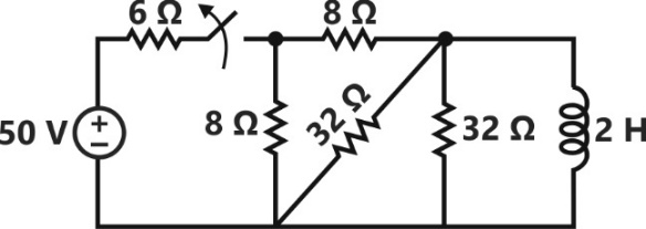


Explanation Locked!
Unlock this branch to view the explanation, track, bookmark and more.
Sign in to UnlockThe transfer function of the system Y(s)/U(s) whose state-space equations are given below is

.


Explanation Locked!
Unlock this branch to view the explanation, track, bookmark and more.
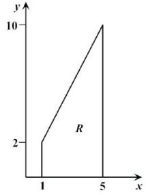
Sign in to UnlockLet, where R is the region shown in the figure and. The value of I equals __________. (Give the answer up to two decimal places).


Explanation Locked!
Unlock this branch to view the explanation, track, bookmark and more.
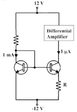
Sign in to UnlockThe circuit shown in the figure uses matched transistors with a thermal voltage . The base currents of the transistors are negligible. The value of the resistance R in that is required to provide 1 bias current for the differential amplifier block shown is __________ . (Give the answer up to one decimal place.)


Explanation Locked!
Unlock this branch to view the explanation, track, bookmark and more.
Sign in to UnlockA function f(x) is defined as . Which one of the following statements is TRUE?

Explanation Locked!
Unlock this branch to view the explanation, track, bookmark and more.
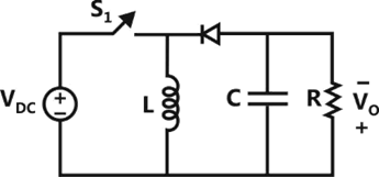
Sign in to UnlockThe input voltage of the buck-boost converter shown below varies from 32 V to 72 V. Assume that all components are ideal, inductor current is continuous, and output voltage is ripple free. The range of duty ratio D of the converter for which the magnitude of the steady-state output voltage remains constant at 48 V is


Explanation Locked!
Unlock this branch to view the explanation, track, bookmark and more.
Sign in to UnlockFor the power semiconductor devices IGBT, MOSFET, Diode and Thyristor, which one of the following statements is TRUE?
Explanation Locked!
Unlock this branch to view the explanation, track, bookmark and more.
Sign in to UnlockFor a system having transfer function, a unit step input is applied at time t= 0. The value of the response of the system at t = 1.5 sec. (rounded off to three decimal places) is

Explanation Locked!
Unlock this branch to view the explanation, track, bookmark and more.
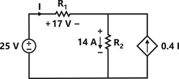
Sign in to UnlockThe power supplied by the 25 V source in the figure shown below is ____________ W.
Explanation Locked!
Unlock this branch to view the explanation, track, bookmark and more.
Sign in to UnlockConsider an electron, a neutron and a proton initially at rest and placed along a straight line such that the neutron is exactly at the center of the line joining the electron and proton. At t = 0, the particles are released but are constrained to move along the same straight line. Which of these will collide first?
Explanation Locked!
Unlock this branch to view the explanation, track, bookmark and more.
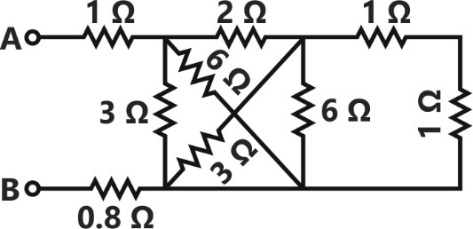
Sign in to UnlockThe equivalent resistance between the terminals A and B is __________ .

Explanation Locked!
Unlock this branch to view the explanation, track, bookmark and more.
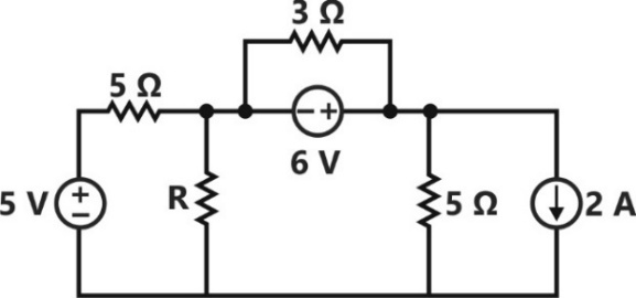
Sign in to UnlockIn the circuit shown below, the maximum power transferred to the resistor R is _____W.
Explanation Locked!
Unlock this branch to view the explanation, track, bookmark and more.
Sign in to UnlockThe transfer function of a system is given by, . Let the output of the system be for the input, . Then the minimum and maximum values of (in radians) are respectively


Explanation Locked!
Unlock this branch to view the explanation, track, bookmark and more.
Sign in to UnlockThe matrix has three distinct eigenvalues and one of its eigenvectors is . Which one of the following can be another eigenvector of A?


Explanation Locked!
Unlock this branch to view the explanation, track, bookmark and more.
Sign in to UnlockConsider the unity feedback control system shown. The value of K that results in a phase margin of the system to be 30° is _________. (Give the answer up to two decimal places).
Explanation Locked!
Unlock this branch to view the explanation, track, bookmark and more.
Sign in to UnlockThe positive, negative, and zero sequence reactances of a wye-connected synchronous generator are 0.2 pu, 0.2 pu and 0.1 pu, respectively. The generator is an open circuit with a terminal voltage of 1 pu. The minimum value of the inductive reactance, in pu, required to be connected between neutral and ground so that the fault current does not exceed 3.75 pu if a single line to ground fault occurs at the terminals is _________ (assume fault impedance to be zero). (Give the answer up to one decimal place.)
Explanation Locked!
Unlock this branch to view the explanation, track, bookmark and more.
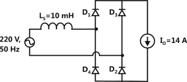
Sign in to UnlockThe figure below shows an uncontrolled diode bridge rectifier supplied from a 220 V, 50 Hz, 1-phase ac source. The load draws a constant current . The conduction angle of the diode in degrees (rounded off to two decimal places) is ____________.


Explanation Locked!
Unlock this branch to view the explanation, track, bookmark and more.
Sign in to UnlockA three-phase, 50 Hz, star-connected cylindrical-rotor synchronous machine is running as a motor. The machine is operated from a 6.6 kV grid and draws current at unity power factor (UPF). The synchronous reactance of the motor is per phase. The load angle is 30 degrees. The power delivered to the motor in kW is __________.

(Give the answer up to one decimal place).
Explanation Locked!
Unlock this branch to view the explanation, track, bookmark and more.
Sign in to UnlockA source is supplying a load through a 2-phase, 3-wire transmission system as shown in figure below. The instantaneous voltage and current in phase-a are V and A, respectively. Similarly for phase-b, the instantaneous voltage and current are A, respectively.


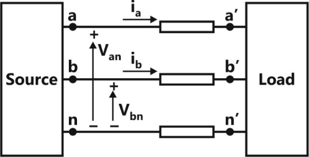
The total instantaneous power flowing from the source to the load is
2200 W

4400 W

Explanation Locked!
Unlock this branch to view the explanation, track, bookmark and more.
Sign in to UnlockTwo parallel connected, three-phase, 50 Hz, 11 kV, star-connected synchronous machines A and B, are operating as synchronous condensers. They together supply 50 MVAR to a 11 kV grid. Current supplied by both the machines are equal. Synchronous reactance’s of machine A and machine B are and , respectively. Assuming the magnetic circuit to be linear, the ratio of excitation current of machine A to that of machine B is ____________. (Given the answer up to two decimal places).


Explanation Locked!
Unlock this branch to view the explanation, track, bookmark and more.
Sign in to UnlockA separately excited DC generator supplies 150 A to a 145 V DC grid. The generator is running at 800 RPM. The armature resistance of the generator is . If the speed of the generator is increased to 1000 RPM, the current in amperes supplied by the generator to the DC gird is ___________. (Give the answer up to one decimal place).

Explanation Locked!
Unlock this branch to view the explanation, track, bookmark and more.
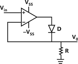
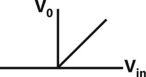
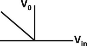
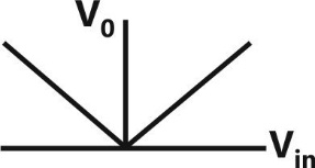
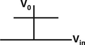
Sign in to UnlockThe approximate transfer characteristic for the circuit shown below with an ideal operational amplifier and diode will be
Explanation Locked!
Unlock this branch to view the explanation, track, bookmark and more.
Sign in to UnlockA 220 V DC series motor runs drawing a current of 30 A from the supply. Armature and field circuit resistances are and , respectively. The load torque varies as the square of the speed. The flux in the motor may be taken as being proportional to armature current. To reduce the speed of the motor by 50%, the resistance in ohms that should be added in series with the armature is _________. (Give the answer up to one decimal place).


Explanation Locked!
Unlock this branch to view the explanation, track, bookmark and more.
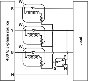
Sign in to UnlockThe load shown in the figure is supplied by a 400 V (line-to-line), 3-phase source (RYB sequence). The load is balanced and inductive, drawing 3464 VA. When the switch S is in position N, the three watt-meters read 577.35 W each. If the switch is moved to position Y, the readings of the watt-meters in watts will be:


Explanation Locked!
Unlock this branch to view the explanation, track, bookmark and more.
Sign in to UnlockA 4 pole induction machine is working as an induction generator. The generator supply frequency is 60 Hz. The rotor current frequency is 5 Hz. The mechanical speed of the rotor in RPM is
Explanation Locked!
Unlock this branch to view the explanation, track, bookmark and more.
Sign in to UnlockA 375 W, 230 V, 50 Hz, capacitor start single-phase induction motor has the following constants for the main and auxiliary windings (at starting): (main winding), (auxiliary winding). Neglecting the magnetizing branch, the value of the capacitance to be added in series with the auxiliary winding to obtain maximum torque at starting is


Explanation Locked!
Unlock this branch to view the explanation, track, bookmark and more.
Sign in to UnlockA three-phase, three winding (1.1 kV/6.6 kV/400 V) transformer is energized from AC mains at the 1.1 kV side. It supplies 900 kVA load at 0.8 power factor lag from the 6.6 kV winding and 300 kVA load at 0.6 power factor lag from the 400 V winding. The RMS line current in ampere drawn by the 1.1 kV winding from the mains is ____________.

(Given the answer up to one decimal place).
Explanation Locked!
Unlock this branch to view the explanation, track, bookmark and more.
Sign in to UnlockA load is supplied by a 230 V, 50 Hz source. The active power P and the reactive power Q consumed by the load are such that .and A capacitor connected across the load for power factor correction generates 1 kVAR reactive power. The worst case power factor after power factor correction is


Explanation Locked!
Unlock this branch to view the explanation, track, bookmark and more.
Sign in to Unlock