
The open collector outputs of two 2-inputs NAND gates are connected to a common pull up resistor. If the input to the gates are P, Q and R, S respectively, the output is equal to


Explanation Locked!
Unlock this branch to view the explanation, track, bookmark and more.
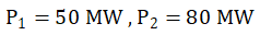
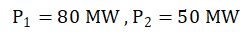
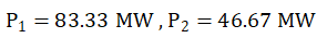
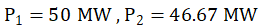
Sign in to UnlockIn a power system, the fuel inputs per hour of plants 1 and 2 are given as
Rs per hour

Rs per hour

The limits generators are:


Find the economic operating schedule of generation, if the load demand is 130MW, neglecting transmission losses
Explanation Locked!
Unlock this branch to view the explanation, track, bookmark and more.
Sign in to UnlockIn standard TTL gates, the totem pole output stage is primarily used to
Explanation Locked!
Unlock this branch to view the explanation, track, bookmark and more.
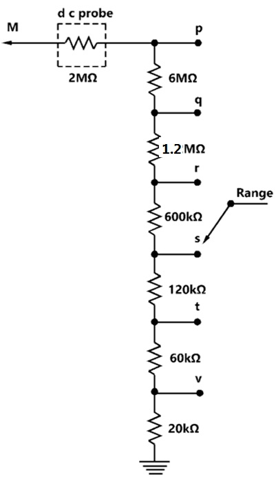
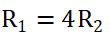
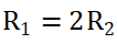
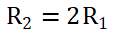
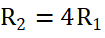
Sign in to UnlockFigure shows the input attenuator of a multimeter. The meter reads full scale with 12V at M, with the range switch at position ‘q’. What is the required voltage at M to obtain full-scale deflection with the range switch at position‘s’?
Explanation Locked!
Unlock this branch to view the explanation, track, bookmark and more.
Sign in to UnlockIn a speed controlled d.c. motor drive, the load torque is 40Nm. At time t=0, the operation is under steady state condition and speed is 500rpm. Under this condition at , the generated torque is instantly increased to 100Nm. The inertia of the drive is . The friction is negligible


(a) Write down the differential equation governing the speed of the drive for t>0
(b) Evaluate the time taken for the speed to reach 1000 rpm
Time taken for the speed to reach 1000 rpm = 4.46 ms
Time taken for the speed to reach 1000 rpm = 8.73 ms
Explanation Locked!
Unlock this branch to view the explanation, track, bookmark and more.
Sign in to Unlock
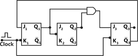
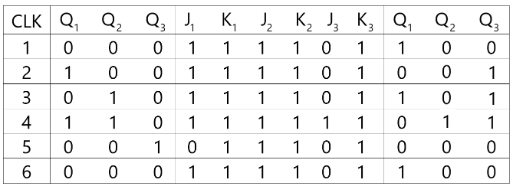
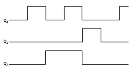
(a) Construct the truth table for the circuit given. are outputs and the clock pulses are the inputs. Unused J, K inputs are assumed to be at logic 1. All flip-flops are rest at power ON.

(b) Sketch the output waveforms at
(c) What function does this circuit perform?
(a)
(b)
(c) MOD-5 counter
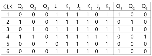
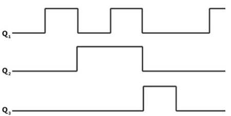
(a)
(b)
(c) MOD-6 counter
(a)
(b)
(c) MOD-4 counter
None
Explanation Locked!
Unlock this branch to view the explanation, track, bookmark and more.
Sign in to UnlockThe phase lead compensation is used to
Explanation Locked!
Unlock this branch to view the explanation, track, bookmark and more.
Sign in to UnlockThe value of computed using Simpson’s rule with a step size of h=0.25 is:

Explanation Locked!
Unlock this branch to view the explanation, track, bookmark and more.
Sign in to UnlockThe effective inductance of the circuit across the terminals A, B in the fig, shown below is:
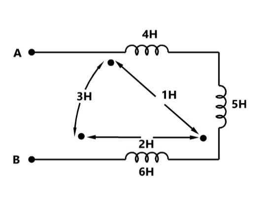
Explanation Locked!
Unlock this branch to view the explanation, track, bookmark and more.
Sign in to UnlockMatch the following
Logic Function
(A) (P) Sum

(B) (Q) NAND

(C) (R) Carry

(S) NOR
Explanation Locked!
Unlock this branch to view the explanation, track, bookmark and more.
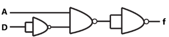
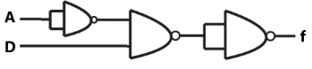
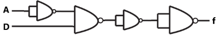
Sign in to UnlockIn a digital combinational circuit with 4 inputs (A, B, C, D), it is required to obtain an output of logical 1 only for the input combination (A=1; B=C=D=0). It is known that the following combinations of input are forbidden:
ABCD= 1010, 1011, 1100, 1101, 1110, 1111
Evaluate the logical expression for the output and realize the same with two input NAND gates. Assume that complements of inputs are not available.
None
Explanation Locked!
Unlock this branch to view the explanation, track, bookmark and more.
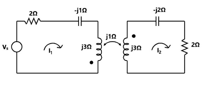
Sign in to UnlockDetermine the impedance seen by the source in the network shown in fig.

Explanation Locked!
Unlock this branch to view the explanation, track, bookmark and more.
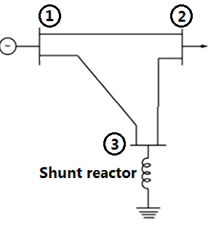
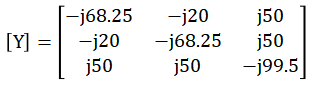
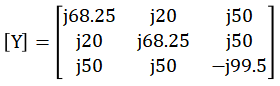
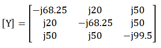
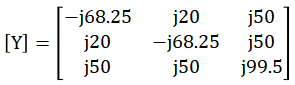
Sign in to UnlockFor the given network in fig., obtain the bus admittance matrix using the data given:

Line between nodes | Impedance p.u. | Half of line charging admittance |
1-2 | 0.0+j0.05 | j1.25 |
1-3 | 0.0+j0.02 | j0.50 |
2-3 | 0.0+j0.02 | j0.50 |
Shunt reactor at node 3 | Impedance |
0.0+j2.0 |
Explanation Locked!
Unlock this branch to view the explanation, track, bookmark and more.
Sign in to UnlockThe state-space representation of a system is given by:

Find the Laplace transform of the state transition matrix. Find also the value of at if


Laplace transform of the state transition matrix

State transition matrix

Explanation Locked!
Unlock this branch to view the explanation, track, bookmark and more.
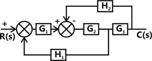
Sign in to UnlockFor block diagram shown in fig. is given by


Explanation Locked!
Unlock this branch to view the explanation, track, bookmark and more.
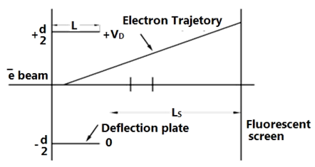
Sign in to UnlockFig shows the electrostatic vertical deflection system of CRT. Given that is the accelerating voltage, the deflection sensitivity (deflection/volt) is proportional to:


Explanation Locked!
Unlock this branch to view the explanation, track, bookmark and more.
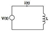
Sign in to UnlockIn the circuit shown in figure, it is desired to have a constant direct current i(t) through the ideal inductor L. the nature of the voltage source v(t) must be:
Explanation Locked!
Unlock this branch to view the explanation, track, bookmark and more.
Sign in to UnlockOne of the applications of current mirror is:
Explanation Locked!
Unlock this branch to view the explanation, track, bookmark and more.
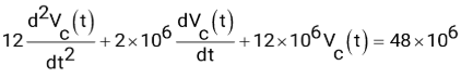
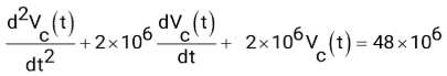
Sign in to UnlockThe switch in the following circuit, shown in fig 3, has been connected to the 12 V source for a long time. At t=0, the switch is thrown to 24V. The value of L=2H,


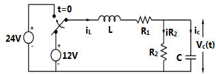
(a) Determine and


(b) Write the differential equation governing for t>0

(c) Compute the steady state value of

(a) 1A, 2V
(b)
(c) =4V
(a) 1A, 1V
(b)
(c) =4V
(a) 1A, 2V
(b)
(c) =4V

(a) 1A, 2V
(b)
(c) =8V
Explanation Locked!
Unlock this branch to view the explanation, track, bookmark and more.
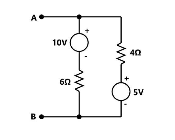
Sign in to UnlockViewed from the terminals A, B the following circuit shown in figure can be reduced to an equivalent circuit of a single voltage source series with a single resistance with the following parameters:
Explanation Locked!
Unlock this branch to view the explanation, track, bookmark and more.
Sign in to UnlockA NPN, silicon transistor is meant for low-current audio amplification. Match its following characteristics against their values:
Characteristics Values
(a) (P) 0.7V

(b) (Q) 0.2V

(c) (R) 6V

(S) 50V
Explanation Locked!
Unlock this branch to view the explanation, track, bookmark and more.
Sign in to UnlockNone of the poles of a linear control system lie in the right half of s-plane. For a bounded input, the output of this system
Explanation Locked!
Unlock this branch to view the explanation, track, bookmark and more.
Sign in to UnlockA power station consists of two synchronous generators A and B of ratings 250MVA and 500MVA with inertia 1.6p.u. and 1p.u., respectively on their own base MVA ratings. The equivalent p.u. inertia constant for the system on 100MVA common base is:
Explanation Locked!
Unlock this branch to view the explanation, track, bookmark and more.
Sign in to UnlockThe number of roots on the equation that lie in the right half of S plane is:

Explanation Locked!
Unlock this branch to view the explanation, track, bookmark and more.
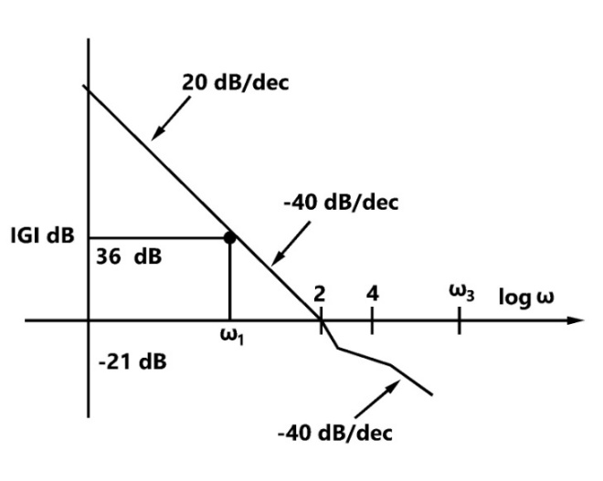
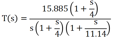
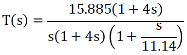
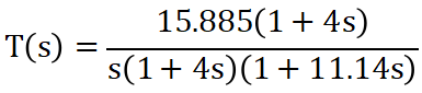
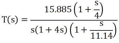
Sign in to UnlockThe asymptotic magnitude Body plot of a system is given fig. Find the transfer function of the system analytically. It is known that the system is minimal phase system
Explanation Locked!
Unlock this branch to view the explanation, track, bookmark and more.
Sign in to UnlockA set of linear equations is represented by the matrix equation Ax=b the necessary condition for the existence of a solution for this system is:
Explanation Locked!
Unlock this branch to view the explanation, track, bookmark and more.
Sign in to UnlockFor the network shown in fig, the zero sequence reactance’s in p.u. are indicated. The zero sequence driving point reactance of the node 3 is:
Explanation Locked!
Unlock this branch to view the explanation, track, bookmark and more.
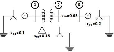
Sign in to UnlockAn alternator is connected to an infinite bus as shown in fig, It delivers 1.0p.u. current at 0.8pf lagging at
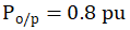
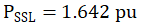
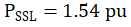
V=1.0 p.u. The reactance of the alternator is 1.2p.u. Determine the active power output and the steady state power limit. Keeping the active power fixed, if the excitation is reduced, find the critical excitation corresponding to operation at stability limit.


Explanation Locked!
Unlock this branch to view the explanation, track, bookmark and more.
Sign in to UnlockThe laws of electromagnetic induction (Faraday’s and Lenz’s law) are summarized in the following equation:


None of the above
Explanation Locked!
Unlock this branch to view the explanation, track, bookmark and more.
Sign in to UnlockThe vector is an Eigen vector of . One of the given values of A is:


Explanation Locked!
Unlock this branch to view the explanation, track, bookmark and more.
Sign in to UnlockA sinusoidal source of voltage V and frequency f is connected to a series circuit of variable resistance, R and a fixed reactance, X. the locus of the tip of the current-phasor I, as R is varied from 0 to ∞ is:
A semicircle with a diameter of

A straight line with a slop of

An ellipse with as major axis

A circle of radius and origin at


Explanation Locked!
Unlock this branch to view the explanation, track, bookmark and more.
Sign in to UnlockWhen the firing angle α of a single phase, fully controlled rectifier feeding constant d.c. current into a load is 30°, the displacement power factor of the rectifier is:
1
0.5


Explanation Locked!
Unlock this branch to view the explanation, track, bookmark and more.
Sign in to UnlockAn electron moves in the X-Y plane with a speed of . Its velocity vector makes an angle of with X-axis. A magnetic field of magnitude T exists along the Y-axis. Compute the magnetic force exerted on the electron and its direction.


The direction of the force is - Z
The direction of the force is - Y
Explanation Locked!
Unlock this branch to view the explanation, track, bookmark and more.
Sign in to UnlockA circuit with a resistor, inductor and capacitor in series is resonant of If all the component values are now doubled, the new resonant frequency is:


still


Explanation Locked!
Unlock this branch to view the explanation, track, bookmark and more.
Sign in to UnlockThe sum of the Eigen values of the matrix A is:

Explanation Locked!
Unlock this branch to view the explanation, track, bookmark and more.
Sign in to UnlockA 3-phase, fully controlled, converter is feeding power into a d.c. load at a constant current of 150A. The rms current through each thyristor of the converter is:
50A
100A


Explanation Locked!
Unlock this branch to view the explanation, track, bookmark and more.
Sign in to UnlockThe uncontrolled electric switch employed in power electric converters is:
Explanation Locked!
Unlock this branch to view the explanation, track, bookmark and more.
Sign in to UnlockA d.c. motor driven from a fully controlled 3 phase converter shown in figure, draws a d.c. current of 100A with negligible ripple.
(a) Sketch the a.c. line current for one cycle

(b) Determine the 3rd and 5th harmonic components of the line current as a percentage of the fundamental current
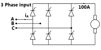
Third harmonic current as a percentage of Fundamental current = 0%
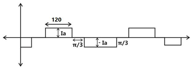
Fifth harmonic current as a percentage of Fundamental current =20%
Third harmonic current as a percentage of Fundamental current = 10%
Explanation Locked!
Unlock this branch to view the explanation, track, bookmark and more.
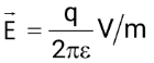
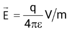
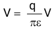
Sign in to UnlockAn infinite number of charges, each equal to ‘q’ are placed along the x=1, x=2 , x=4, x=8 , x=16 and so on. Find the potential and electron field at point x=0, due to these systems of charges.
Explanation Locked!
Unlock this branch to view the explanation, track, bookmark and more.
Sign in to UnlockThe neutral of 10MVA, 11KV alternator is earthed through a resistance of 5 ohms. The earth fault relay is set to operate at 0.75A. The CT’s have a ratio of 1000:5.
What percentage of the alternator winding is protected?
Explanation Locked!
Unlock this branch to view the explanation, track, bookmark and more.
Sign in to UnlockThe inverse of A is:


Explanation Locked!
Unlock this branch to view the explanation, track, bookmark and more.
Sign in to UnlockThe MOSFET switch in its on-state may be considered equivalent to:
Explanation Locked!
Unlock this branch to view the explanation, track, bookmark and more.
Sign in to UnlockIn a commutation circuit employed to turn off an SCR, satisfactory turn-off is obtained when
Explanation Locked!
Unlock this branch to view the explanation, track, bookmark and more.
Sign in to UnlockThe output of a linear time invariant control system is c(t) for a certain input r(t). If r(t) modified by passing it through a block whose transfer function is and then applied to the system, the modified output of the system would be


Explanation Locked!
Unlock this branch to view the explanation, track, bookmark and more.
Sign in to UnlockA synchronous generator connected to an infinite bus is overexcited. Considering only the reactive power, from the point of view of the system, the machine acts as
Explanation Locked!
Unlock this branch to view the explanation, track, bookmark and more.
Sign in to UnlockThe armature of a single phase alternator is completely wound with T single turn coils distributed uniformly. The induced voltage in each turn is 2V (rms). The emf of the whole winding is
Explanation Locked!
Unlock this branch to view the explanation, track, bookmark and more.
Sign in to UnlockThe Laplace transform of is:


None of the above
Explanation Locked!
Unlock this branch to view the explanation, track, bookmark and more.
Sign in to UnlockA d.c. voltmeter has a sensitivity of 1000 Ω/volt. When it measures half full scale in 100V range, the current through the voltmeter is
Explanation Locked!
Unlock this branch to view the explanation, track, bookmark and more.
Sign in to UnlockA 240 V DC shunt motor with an armature resistance of 0.5Ω has a full load current of 40A. Find the ratio of the stalling torque to the full load torque when a resistance of 1Ω is connected in series with the armature?
Explanation Locked!
Unlock this branch to view the explanation, track, bookmark and more.
Sign in to UnlockA DC shunt generator delivers 60KW at 240V and 360 rpm. The armature and field resistances are 0.015Ω and 60Ω respectively. Calculate the speed of the machine running as a shunt motor and taking 60KW input at 240V. Allow 1 volt per brush for contact drop.
Explanation Locked!
Unlock this branch to view the explanation, track, bookmark and more.
Sign in to UnlockMatch the column
Circuit
(a) (P) High-pass filter
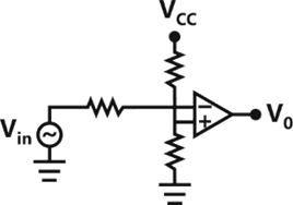
(b) (Q) Amplifier
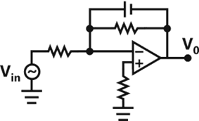
(c) (R) Comparator
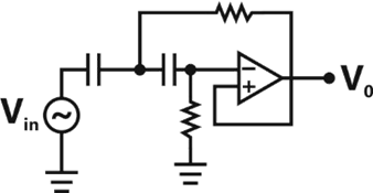
(S) Low-pass filter
Explanation Locked!
Unlock this branch to view the explanation, track, bookmark and more.
Sign in to UnlockA moving coil galvanometer is made into a d.c. ammeter by connecting
Explanation Locked!
Unlock this branch to view the explanation, track, bookmark and more.
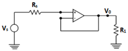
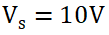
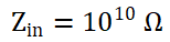
Sign in to UnlockIn the circuit shown in fig and, . For the op-amp, , R1 = 100 kΩ and R0 = 50Ω. For V0 = 10V, calculate and and estimate the input resistance of the circuit


Explanation Locked!
Unlock this branch to view the explanation, track, bookmark and more.
Sign in to UnlockA moving coil instrument, whose resistance is 5Ω and whose working current (for full-scale deflection) is 0.015A, is to be used, with a manganin shunt, to measure 100A. calculate the error caused by a 10℃ rise in temperature, if the temperature coefficient of copper and manganin are 0.004 ohm/℃, and 0.00015 ohm/℃ respectively.
Explanation Locked!
Unlock this branch to view the explanation, track, bookmark and more.
Sign in to UnlockThe efficiency of a 100KVA transformer is 0.98 at full as well as at half load. For this transformer at full load the copper loss
Explanation Locked!
Unlock this branch to view the explanation, track, bookmark and more.
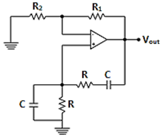
Sign in to UnlockShow that the circuit given in figure will work as an oscillator at , if ?

Explanation Locked!
Unlock this branch to view the explanation, track, bookmark and more.
Sign in to UnlockThe magnetizing current in a transformer is rich in
harmonic

harmonic

harmonic

harmonic

Explanation Locked!
Unlock this branch to view the explanation, track, bookmark and more.
Sign in to UnlockA 3 phase squirrel cage induction motor has a full load efficiency of 0.8 and a maximum efficiency of 0.9. it is operated at a slip of 0.6 by applying a reduced voltage. The efficiency of the motor at this operating point is:
Explanation Locked!
Unlock this branch to view the explanation, track, bookmark and more.
Sign in to UnlockA 50Hz transformer having equal hysteresis and eddy current losses at rated excitation is operated at 45Hz at 90% of its rated voltage. Compared to rated operating point, the core losses under this condition:
Explanation Locked!
Unlock this branch to view the explanation, track, bookmark and more.
Sign in to UnlockIn a 50 KVA, 11 KV/400V transformers, the iron and copper losses are 500W and 600W respectively under rated conditions. Calculate the efficiency on unity power factor at full load. Find the load for maximum efficiency and the iron and copper losses corresponding to this load.
Explanation Locked!
Unlock this branch to view the explanation, track, bookmark and more.
Sign in to UnlockMatch the column
Test Machine
(A) No load and (P) Transformer
blocked rotor test
(B) Sumpner’s test (Q) Induction machine
(C) Swinburne’s test (R) Synchronous machine
(S) DC machine
Explanation Locked!
Unlock this branch to view the explanation, track, bookmark and more.
Sign in to UnlockA 50 hp, 6 pole, 50 Hz slip-ring induction motor runs at 960 rpm on full load with a rotor current of 40A. Allowing 300W for the copper loss in the short circuiting gear and 1200W for mechanical losses, find the resistance per phase of the 3 phase rotor winding.

Explanation Locked!
Unlock this branch to view the explanation, track, bookmark and more.
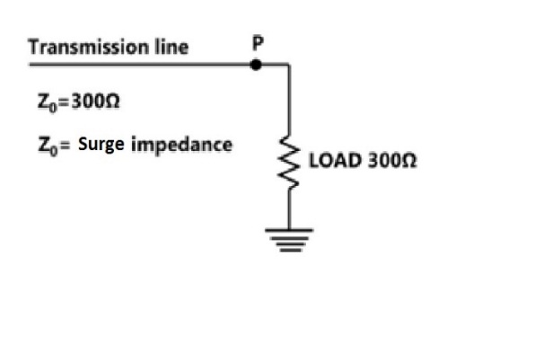
Sign in to UnlockThe reflection coefficient for the transmission line shown in fig. at P is:
Explanation Locked!
Unlock this branch to view the explanation, track, bookmark and more.
Sign in to UnlockSeries capacitive compensation in EHV transmission lines is used to
Explanation Locked!
Unlock this branch to view the explanation, track, bookmark and more.
Sign in to UnlockBulk power transmission over long HVDC lines is preferred, on account of
Explanation Locked!
Unlock this branch to view the explanation, track, bookmark and more.
Sign in to UnlockIf the length of a wire of resistance R is uniformly stretched to n times its original value, its new resistance is
nR


Explanation Locked!
Unlock this branch to view the explanation, track, bookmark and more.
Sign in to UnlockA cable has the following characteristics. .

The velocity of wave propagation through the cable is:
Explanation Locked!
Unlock this branch to view the explanation, track, bookmark and more.
Sign in to UnlockA shunt reactor of 100MVAr is operated at 98% of its rated voltage and at 96% of its rated frequency. The reactive power absorbed by the reactor is:
Explanation Locked!
Unlock this branch to view the explanation, track, bookmark and more.
Sign in to UnlockEach conductor of a 33KV, 3-phase system is suspended by a string of three similar insulars. The ratio of shunt capacitance to mutual capacitance is 0.1. Calculate the voltage across each insulator, and the string efficiency.
Explanation Locked!
Unlock this branch to view the explanation, track, bookmark and more.
Sign in to UnlockA circuit consisting of a single resistor R and an inductor L in series is driven by a 25V RMS, 50 Hz sinusoidal voltage source. A capacitor is to be placed in parallel with the source to improve the power factor. Given that the average power dissipated in the R is 100W and that the reactive power delivered to the L is 75VAR, what value of C will yield a 0.9 p.f. lagging as seen by the source?
Explanation Locked!
Unlock this branch to view the explanation, track, bookmark and more.
Sign in to Unlock