
An n-channel JFET, having a pinch off voltage of −5V, shows a trans-conductance of 1mA/V when the applied gate-to-source voltage is -3V. Its maximum trans-conductance (in mA/V) is


Explanation Locked!
Unlock this branch to view the explanation, track, bookmark and more.
Sign in to UnlockA connected network of N > 2 nodes has at most one branch directly connecting any pair of nodes. The graph of the network
Explanation Locked!
Unlock this branch to view the explanation, track, bookmark and more.
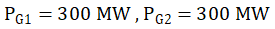
Sign in to UnlockA power system has two generators with the following cost curves:
Generator 1: (Thousand Rupees/Hour)

Generator 2: (Thousand Rupees/Hour)

The generator limits are


A load demand of 600 MW is supplied by the generators in an optimal manner. Neglecting losses in the transmission network, determine the optimal generation of each generator.


Explanation Locked!
Unlock this branch to view the explanation, track, bookmark and more.
Sign in to UnlockThe output of a logic gate is “1” when all its inputs are at logic “0”. The gate is either.
Explanation Locked!
Unlock this branch to view the explanation, track, bookmark and more.
Sign in to UnlockIn case of an armature controlled separately excited dc motor drive with closed-loop speed control, an inner current loop is useful because it
Explanation Locked!
Unlock this branch to view the explanation, track, bookmark and more.
Sign in to UnlockResistances and have, respectively nominal values of 10Ω and 5Ω, and tolerances of ±5% and ±10%. The range of values for the parallel combination of and is


Explanation Locked!
Unlock this branch to view the explanation, track, bookmark and more.
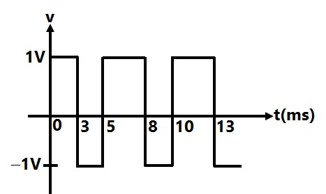
Sign in to UnlockConsider the voltage waveform v, shown in figure.
Explanation Locked!
Unlock this branch to view the explanation, track, bookmark and more.
Sign in to UnlockGiven two coupled inductors and , their mutual inductance M satisfies


Explanation Locked!
Unlock this branch to view the explanation, track, bookmark and more.
Sign in to UnlockA separately excited dc motor is controlled by varying its armature voltage using a single phase full-converter bridge as shown in figure; the field current is kept constant at the rated value. The motor has an armature resistance of 0.2Ω, and the motor voltage constant is 2.5V (rad/sec). The motor is driving a mechanical load having a constant torque of 140 Nm. The triggering angle of the converter is.

The armature current can be assumed to be continuous and ripple free.
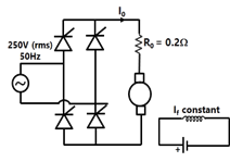
(a) Calculate the motor armature current
(b) Evaluate the motor speed in rad/sec
(c) Calculate the RMS value of the fundamental component of the input current to the bridge.
Explanation Locked!
Unlock this branch to view the explanation, track, bookmark and more.
Sign in to UnlockGiven the characteristic equation

Sketch the root locus as K varies from zero to infinity. Find the angle and real axis intercept of the asymptotes, break-away/break-in points, and imaginary axis crossing points, if any.
Root Locus diagram
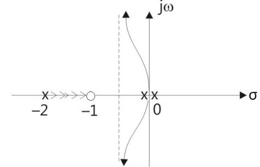
Angle of asymptotes
= 90

= 270

breakaway point s=0 and Centroid = -0.5
breakaway point s=1 and Centroid = -0.5
Explanation Locked!
Unlock this branch to view the explanation, track, bookmark and more.
Sign in to UnlockA passive 2-port network is in a steady-state. Compared to its input, the steady state output can never offer
Explanation Locked!
Unlock this branch to view the explanation, track, bookmark and more.
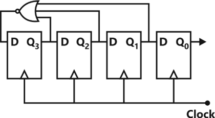
Sign in to UnlockFor the ring counter shown in figure, find the steady state sequence if the initial state of the counters is 1110 (i.e., Q3, Q2, Q1, Q0 = 1110). Determine the MOD number of the counter.
Explanation Locked!
Unlock this branch to view the explanation, track, bookmark and more.
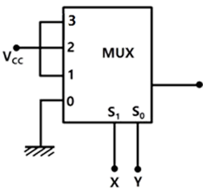
Sign in to UnlockThe output of the 4-to-1 MUX shown in figure is


Explanation Locked!
Unlock this branch to view the explanation, track, bookmark and more.
Sign in to UnlockFor the Y-bus matrix given in per unit values, where the first, second, third and fourth row refers to bus 1, 2, 3 and 4 respectively, draw the reactance diagram.

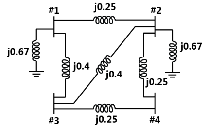
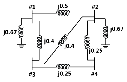
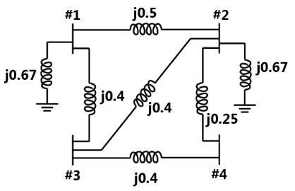
None
Explanation Locked!
Unlock this branch to view the explanation, track, bookmark and more.
Sign in to UnlockA voltage commutated thyristor chopper circuit is shown in figure. The chopper is operated at 500 Hz with 50% duty ratio. The load takes a constant current of 20A.
(a) Evaluate the circuit turn off time for the main thyristor .

(b) Calculate the value of inductor L, if the peak current through the main thyristor is limited to 180% of the load current.
(c) Calculate the maximum instantaneous output voltage of the chopper.
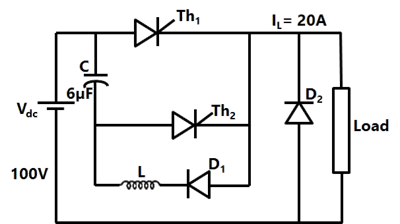
L=0.234mH
Maximum instantaneous voltage = 200V
Maximum instantaneous voltage = 400V
Explanation Locked!
Unlock this branch to view the explanation, track, bookmark and more.
Sign in to UnlockGiven the homogeneous state-space equation

The steady state value, given the initial state value of is


Explanation Locked!
Unlock this branch to view the explanation, track, bookmark and more.
Sign in to UnlockAmong the following four, the slowest ADC (analog-to-digital converter) is
Explanation Locked!
Unlock this branch to view the explanation, track, bookmark and more.
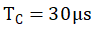
Sign in to UnlockIn the single-stage transistor amplifier circuit shown in Fig., the capacitor is removed. Then the ac small-signal mid-band voltage gain of the amplifier.


Explanation Locked!
Unlock this branch to view the explanation, track, bookmark and more.
Sign in to UnlockA sample-and-hold (S/H) circuit, having a holding capacitor of 0.1nF, is used at the input of an ADC (analog-to-digital converter). The conversion time of the ADC is 1µsec, and during this time, the capacitor should not lose more than 0.5% of the charge put across it during the sampling time. The maximum value of the input signal to the S/H circuit is 5V. The leakage current of the S/H circuit should be less than
Explanation Locked!
Unlock this branch to view the explanation, track, bookmark and more.
Sign in to UnlockAn intel 8085 processor is executing the program given below.
MVI A, 10H
MVI B, 10H
BACK: NOP
ADD B
RLC
JNC BACK
HLT
The number of times that the operation NOP will be executed is equal to
Explanation Locked!
Unlock this branch to view the explanation, track, bookmark and more.
Sign in to UnlockThe transistor in the amplifier circuit shown in figure is biased at . Use


AC small signal mid-band voltage gain = -6.623
AC small signal mid-band voltage gain = -5.565
Value of for the circuit to have a lower cutoff
frequency of 10 Hz = 265.08 micro F
Value of for the circuit to have a lower cutoff
frequency of 10 Hz = 365.08 micro F
Explanation Locked!
Unlock this branch to view the explanation, track, bookmark and more.
Sign in to UnlockA unit step voltage is applied at t = 0 to a series RL circuit with zero initial conditions.
It is possible for the current to be oscillatory.
The voltage across the resistor at is zero.

The energy stored in the inductor in the steady state is zero.
The resistor current eventually falls to zero.
Explanation Locked!
Unlock this branch to view the explanation, track, bookmark and more.
Sign in to UnlockThe polar plot of a type-1, 3-pole, open-loop system is shown in Figure, the closed loop system is
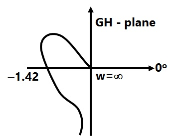
Explanation Locked!
Unlock this branch to view the explanation, track, bookmark and more.
Sign in to UnlockTwo incandescent light bulbs of 40W and 60W rating are connected in series across the mains.
Then
Explanation Locked!
Unlock this branch to view the explanation, track, bookmark and more.
Sign in to UnlockA synchronous generator is connected to an infinite bus through a lossless double circuit transmission line. The generator is delivering 1.0 per unit power at a load angle of 30° when a sudden fault reduces the peak power that can be transmitted to 0.5 per unit. After clearance of fault, the peak power that can be transmitted becomes 1.5 per unit. Find the critical clearing angle.
Explanation Locked!
Unlock this branch to view the explanation, track, bookmark and more.
Sign in to UnlockThe asymptotic approximation of the log-magnitude versus frequency plot of a minimum phase system with real poles and one zero is shown in figure. Its transfer function is
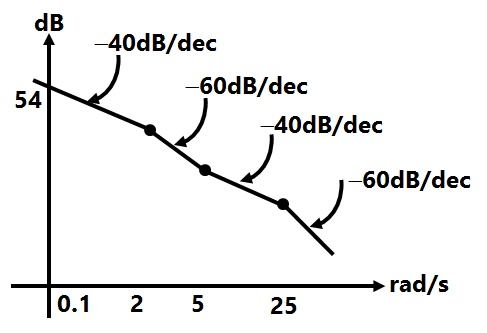


Explanation Locked!
Unlock this branch to view the explanation, track, bookmark and more.
Sign in to Unlockand are steady state d-axis synchronous reactance, transient d-axis reactance and sub-transient d-axis reactance of a synchronous machine respectively. Which of the following statement is true?


Explanation Locked!
Unlock this branch to view the explanation, track, bookmark and more.
Sign in to UnlockA unit feedback system has an open-loop transfer function of

(a) Determine the magnitude of G(jω) in dB at an angular frequency of ω= 20 rad/sec.
(b) Determine the phase margin in degrees.
(c) Determine the gain margin in dB.
(d) Is the system stable or unstable?
Explanation Locked!
Unlock this branch to view the explanation, track, bookmark and more.
Sign in to UnlockConsider the star network shown in Figure. The resistance between terminals A and B with C open is 6Ω, between terminals B and C with A open is 11Ω, and between terminals C and A with B open is 9Ω. Then
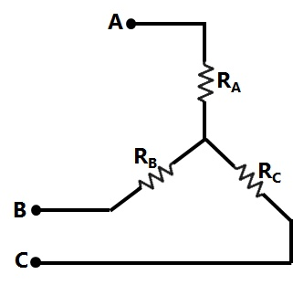


Explanation Locked!
Unlock this branch to view the explanation, track, bookmark and more.
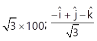
Sign in to UnlockThe electric field (in volts/metre) at the point (1, 1, 0) due to a point charge of +1µC located at (−1, 1, 1) (coordinates in metres) is


Explanation Locked!
Unlock this branch to view the explanation, track, bookmark and more.
Sign in to UnlockA 75 MVA, 10 KV, synchronous generator has The value (in p.u.) on a base of 100 MVA, 11 KV is:


Explanation Locked!
Unlock this branch to view the explanation, track, bookmark and more.
Sign in to UnlockGiven the potential function in free space to be volts, the magnitude (in volts/metre) and the direction of the electric field at a point (1, -1, 1), where the dimensions are in metres, are


Explanation Locked!
Unlock this branch to view the explanation, track, bookmark and more.
Sign in to UnlockThe main reason for connecting a pulse transformer at the output stage of a thyristor triggering circuit is to
Explanation Locked!
Unlock this branch to view the explanation, track, bookmark and more.
Sign in to UnlockA 50 Hz alternator is rated 500 MVA, 20 kV, with per unit and per unit. It supplied a purely resistive load of 400 MW at 20 kV. The load is connected directly across the generator terminals when a symmetrical fault occurs at the load terminals. The initial RMS current in the generator in per unit is


Explanation Locked!
Unlock this branch to view the explanation, track, bookmark and more.
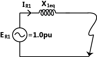
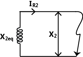
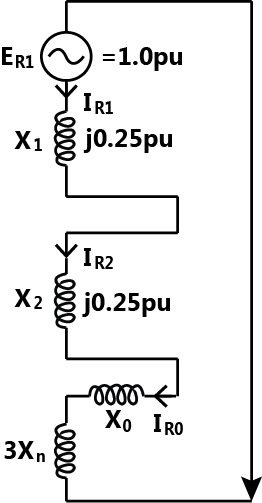
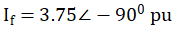
Sign in to UnlockA single line-to-ground fault occurs on an unloaded generator in phase a positive, negative, and zero sequence impedances of the generator are j0.25p.u, j0.25p.u, and j0.15p.u. respectively. The generator neutral is grounded through a reactance of j0.05p.u. The pre fault generator terminal voltage is 1.0p.u.
The positive, negative, and zero sequence networks for the fault given are
Positive sequence diagram:
Negative sequence diagram:
Zero sequence diagram:

Interconnection of the sequence networks for the fault analysis
Explanation Locked!
Unlock this branch to view the explanation, track, bookmark and more.
Sign in to UnlockAC-to-DC circulating current dual converters is operated with the following relationship between their triggering angles ( and ).


Explanation Locked!
Unlock this branch to view the explanation, track, bookmark and more.
Sign in to UnlockIn the protection of transformers, harmonic restrain is used to guard against
Explanation Locked!
Unlock this branch to view the explanation, track, bookmark and more.
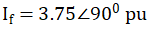
Sign in to UnlockA half-wave thyristor converter supplies a purely inductive load, as shown in Figure. If the triggering angle of the thyristor is 120°, the extinction angle will be
Explanation Locked!
Unlock this branch to view the explanation, track, bookmark and more.
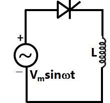
Sign in to UnlockA single-phase full bridge voltage source inverter feeds a purely inductive load, as shown in figure, where , , , are power transistors and , , , are feedback diodes. The inverter is operated in square-wave mode with a frequency of 50 Hz. If the average load current is zero, what is the time duration of conduction of each feedback diode in a cycle?


Explanation Locked!
Unlock this branch to view the explanation, track, bookmark and more.
Sign in to UnlockGiven the relationship between the input u(t) and the output y(t) to be, the transfer function is


Explanation Locked!
Unlock this branch to view the explanation, track, bookmark and more.
Sign in to UnlockIn a series RLC circuit at resonance, the magnitude of the voltage developed across the capacitor.
Explanation Locked!
Unlock this branch to view the explanation, track, bookmark and more.
Sign in to UnlockA 240 V single-phase ac source is connected to a load with an impedance of . A capacitor is connected in parallel with the load. If the capacitor supplied 1250 VAR, the real power supplied by the source is

Explanation Locked!
Unlock this branch to view the explanation, track, bookmark and more.
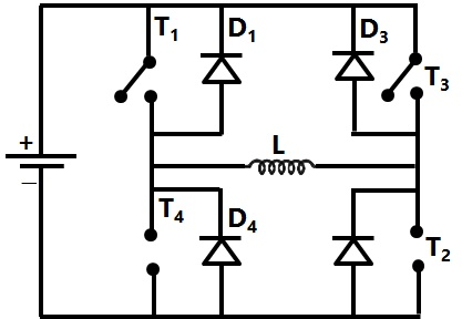
Sign in to UnlockDetermine the resonance frequency and the Q-factor of the circuit shown in figure.
Data: R = 10Ω, C = 3µF, , and M = 10 mH.


Explanation Locked!
Unlock this branch to view the explanation, track, bookmark and more.
Sign in to UnlockIt is desirable to eliminate 5th harmonic voltage from the phase voltage of an alternator. The coils should be short-pitched by an electrical angle of
Explanation Locked!
Unlock this branch to view the explanation, track, bookmark and more.
Sign in to UnlockFigure shows the magnetization curves of an alternator at rated armature current, unity power factor and also at no load. The magnetization curve for rated armature current, 0.8 power factor leading is given by
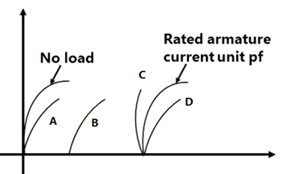
Explanation Locked!
Unlock this branch to view the explanation, track, bookmark and more.
Sign in to UnlockAn op-amp has an open-loop gain of and an open-loop upper cutoff frequency of 10 Hz. If this op-amp is connected as an amplifier with a closed gain of 100, then the new upper cutoff frequency is

Explanation Locked!
Unlock this branch to view the explanation, track, bookmark and more.
Sign in to UnlockA star-connected 440 V, 50 Hz alternators has per phase synchronous reactance of 10Ω. It supplies a balanced capacitive load current of 20A, as shown in the per phase equivalent circuit of Figure. It is desirable to have zero voltage regulation. The load power factor should be
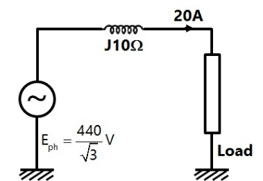
Explanation Locked!
Unlock this branch to view the explanation, track, bookmark and more.
Sign in to UnlockFor the oscillator circuit shown in figure, the expression for the time period of oscillation can be given by (where τ = RC)
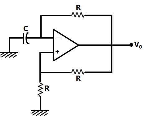
ln3

ln3

ln2
ln2
Explanation Locked!
Unlock this branch to view the explanation, track, bookmark and more.
Sign in to UnlockAn electric motor with ‘constant output power’ will have a torque speed characteristic in the form of a
Explanation Locked!
Unlock this branch to view the explanation, track, bookmark and more.
Sign in to UnlockIf an energy meter disc makes 10 revolutions in 100 seconds when a load of 450 W is connected to it, the meter constant (in rev/kWh) is
Explanation Locked!
Unlock this branch to view the explanation, track, bookmark and more.
Sign in to UnlockA 50 kW synchronous motor is tested by driving it by another motor. When the excitation is not switched on, the driving motor takes 800W. When the armature is short circuited and the rated armature current of 10A is passed through it, the driving motor required 2500 W. On open-circuiting the armature with rated excitation, the driving motor takes 1800W.
Calculate the efficiency of the synchronous motor at 50% load. Neglect the losses in the driving motor.
Explanation Locked!
Unlock this branch to view the explanation, track, bookmark and more.
Sign in to UnlockThe minimum number of wattmeter (s) required to measure 3-phase, 3-wire balanced or unbalanced power is
Explanation Locked!
Unlock this branch to view the explanation, track, bookmark and more.
Sign in to UnlockTwo identical synchronous generators, each of 100 MVA, are working in parallel supplying 100 MVA at 0.8 lagging p.f. at rated voltage. Initially the machines are sharing load equally. If the field current of first generator is reduced by 5% and of the second generator increased by 5%, find the sharing of load (MW and MVAR) between the generators. Assume 0.8 p.u., no field saturation and rated voltage across load. Reasonable approximations may be made.

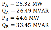
Explanation Locked!
Unlock this branch to view the explanation, track, bookmark and more.
Sign in to UnlockIn a dc motor running at 2000 rpm, the hysteresis and eddy current losses are 500W and 200W respectively. If the flux remains constant, calculate the speed at which the total iron losses are halved.
Explanation Locked!
Unlock this branch to view the explanation, track, bookmark and more.
Sign in to UnlockAn op-amp having a slew rate of 62.8 V/µsec, is connected in a voltage follower configuration. If the maximum amplitude of the input sinusoid is 10V, then the minimum frequency at which the slew rate limited distortion would set in at the output is
Explanation Locked!
Unlock this branch to view the explanation, track, bookmark and more.
Sign in to UnlockA 100µA ammeter has an internal resistance of 100Ω. For extending its range to measure 500µA, the shunt required is of resistance (in Ω)
Explanation Locked!
Unlock this branch to view the explanation, track, bookmark and more.
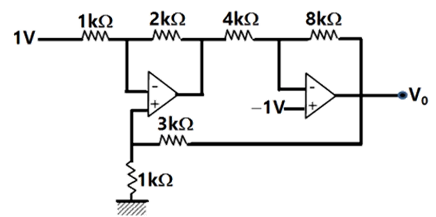
Sign in to UnlockFor the op-amp circuit shown in figure, determine the output voltage . Assume that the op-amps are ideal.

Explanation Locked!
Unlock this branch to view the explanation, track, bookmark and more.
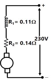
Sign in to UnlockA dc series motor is rated 230V, 1000 rpm, 80 A (refer to figure), the series field resistance is 0.11Ω, and the armature resistance is 0.14Ω. If the flux at an armature current of 20A is 0.4 times of that under rated condition, calculate the speed at this reduced armature current of 20A.
Explanation Locked!
Unlock this branch to view the explanation, track, bookmark and more.
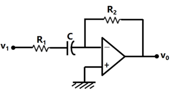
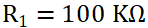
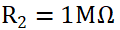
Sign in to UnlockA simple active filter is shown in Figure. Assume ideal op-amp. Derive the transfer function of the circuit, and state the type of the filter (i.e., high-pass, low-pass, band-pass, or band-reject). Determine the required values of , and C in order for the filter to have a 3-dB frequency of 1 kHz, a high frequency input resistance of 100 kΩ, and a high frequency gain magnitude of 10.


Explanation Locked!
Unlock this branch to view the explanation, track, bookmark and more.
Sign in to UnlockA single-phase transformer is to be switched to the supply to have minimum inrush current. The switch should be closed be
Maximum supply voltage
Zero supply voltage
maximum supply voltage

maximum supply voltage

Explanation Locked!
Unlock this branch to view the explanation, track, bookmark and more.
Sign in to UnlockThe core flux of a practical transformer with a resistive load
Explanation Locked!
Unlock this branch to view the explanation, track, bookmark and more.
Sign in to UnlockThe hysteresis loop of a magnetic material has an area of 5 with the scales given as 1 cm = 2AT and 1 cm = 50mWb. At 50 Hz, the total hysteresis loss is

Explanation Locked!
Unlock this branch to view the explanation, track, bookmark and more.
Sign in to UnlockA 3-phase transformer has rating of 20 MVA, 200 kV (star)–33 kV (delta) with leakage reactance of 12%. The transformer reactance (in ohms) referred to each phase of the L.V delta-connected side is
Explanation Locked!
Unlock this branch to view the explanation, track, bookmark and more.
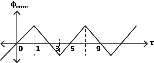
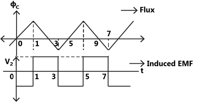
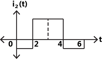
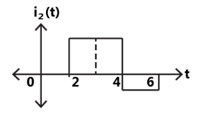
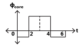
Sign in to UnlockAn ideal transformer has a linear B-H characteristic with a finite slope and a turns ratio 1:1. The primary of the transformer is energized with an ideal current source, producing the signal I as shown in figure. Sketch the shape (neglecting the scale factor) of the following signals, labeling the time axis clearly:
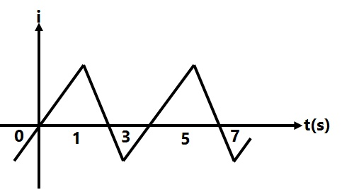
(a) The core flux with the secondary of the transformer open
(b) The open-circuited secondary terminal voltage
(c) The short-circuited secondary current
(d) The core flux with the secondary of the transformer short-circuited.


(a)
(b)
(c)
(d)
(a)
(b)
(c)
(d)
(a)
(b)
(c)
(d)
None
Explanation Locked!
Unlock this branch to view the explanation, track, bookmark and more.
Sign in to UnlockA 50 Hz balanced three-phase, Y-connected supply is connected to a balanced three phase Y-connected load. If the instantaneous phase-α of the supply voltage is and the phase-α of the load current is , the instantaneous three-phase power is


A constant with a magnitude of

A constant with a magnitude of

Time-varying with an average value of and a frequency of 100Hz
Time-varying with an average value of and a frequency of 50 Hz

Explanation Locked!
Unlock this branch to view the explanation, track, bookmark and more.
Sign in to UnlockA lossless radial transmission line with surge impedance loading
Explanation Locked!
Unlock this branch to view the explanation, track, bookmark and more.
Sign in to UnlockConsider the model shown in Figure of a transmission line with a series capacitor at its mid-point. The maximum voltage on the line is at the location


Explanation Locked!
Unlock this branch to view the explanation, track, bookmark and more.
Sign in to UnlockA power system has two synchronous generators. The Governor-turbine characteristics corresponding to the generators are. Where f denotes the system frequency in Hz, and and are, respectively, the power outputs (in MW) of turbines 1 and 2 assuming the generators and transmission network to be lossless, the system frequency for a total load of 400 MW is

Explanation Locked!
Unlock this branch to view the explanation, track, bookmark and more.
Sign in to UnlockThe conductors of a 10 km long, single phase, two wire line are separated by a distance of 1.5m. The diameter of each conductor is 1 cm. If the conductors are of copper, the inductance of the circuit is
Explanation Locked!
Unlock this branch to view the explanation, track, bookmark and more.
Sign in to UnlockA 132 kV transmission line AB is connected to a cable BC. The characteristic impedances of the overhead line and the cable are 400Ω and 80Ω respectively. Assume that these are purely resistive. A 250 kV switching surge travels from A to B.
(a) Calculate the value of this voltage surge when it first reaches C.
(b) Calculate the value of the reflected component of this surge when the first reflection reaches A.
(c) Calculate the surge current in the cable BC.
Explanation Locked!
Unlock this branch to view the explanation, track, bookmark and more.
Sign in to Unlock