
For the system
with u as unit impulse and with zero initial state, the output, y, becomes


Explanation Locked!
Unlock this branch to view the explanation, track, bookmark and more.
Sign in to UnlockA single input single output system with y as output and u as input, is described by

For the above system find an input u(t), with zero initial condition, that produces the same output as with no input and with the initial conditions.


None of these
Explanation Locked!
Unlock this branch to view the explanation, track, bookmark and more.
Sign in to UnlockLet s(t) be the step response of a linear system with zero initial conditions; then the response of this system to an input u(t) is


Explanation Locked!
Unlock this branch to view the explanation, track, bookmark and more.
Sign in to UnlockLet Y(s) be the Laplace transformation of the function y(t), then the final value of the function is


Explanation Locked!
Unlock this branch to view the explanation, track, bookmark and more.
Sign in to UnlockThe graph of an electrical network has N nodes and B branches. The number of links, L, with respect to the choice of a tree, is given by
Explanation Locked!
Unlock this branch to view the explanation, track, bookmark and more.
Sign in to UnlockA current impulse, , is forced through a capacitor C. The voltage, , across the capacitor is given by


5t
5u(t) − C


Explanation Locked!
Unlock this branch to view the explanation, track, bookmark and more.
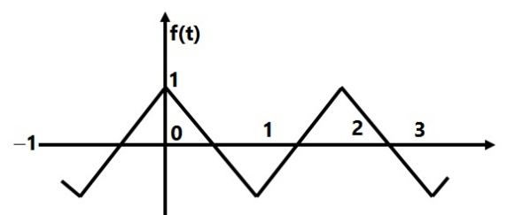
Sign in to UnlockFourier Series for the waveform, f(t) shown in Figure is


Explanation Locked!
Unlock this branch to view the explanation, track, bookmark and more.
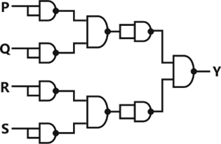
Sign in to UnlockFor the circuit shown in figure, the Boolean expression for the output Y in terms of inputs P, Q, R and S is


Explanation Locked!
Unlock this branch to view the explanation, track, bookmark and more.
Sign in to UnlockThe forward resistance of the diode shown in Figure is 5Ω and the remaining parameters are same as those of an ideal diode. The dc component of the source current is


Explanation Locked!
Unlock this branch to view the explanation, track, bookmark and more.
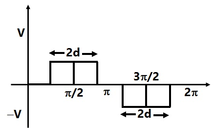
Sign in to UnlockWhat is the RMS value of the voltage waveform shown in Figure?
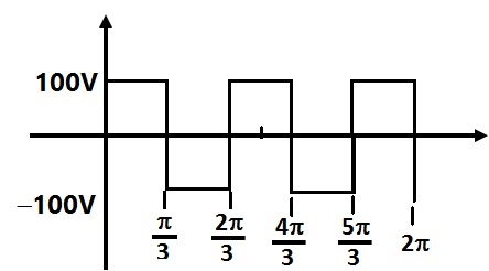


200 V
100 V
Explanation Locked!
Unlock this branch to view the explanation, track, bookmark and more.
Sign in to UnlockA two port network, shown in Figure is described by the following equations.


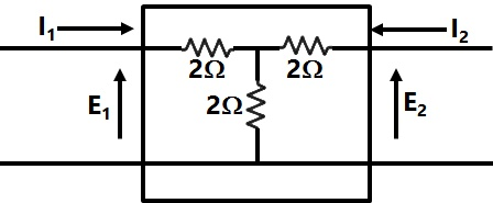
The admittance parameters for the network shown are

0.5 mho, 1 mho, 2 mho and 1 mho respectively
mho, mho, mho and mho respectively


0.5 mho, 0.5 mho, 1.5 mho and 2 mho respectively
mho, mho, mho and mho respectively


Explanation Locked!
Unlock this branch to view the explanation, track, bookmark and more.
Sign in to UnlockIn the circuit shown in Figure, it is found that the input ac voltage (v) and current I are in phase. The coupling coefficient is , where M is the mutual inductance between the two coils. The value of K and the dot polarity of the coil P-Q are

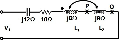
Explanation Locked!
Unlock this branch to view the explanation, track, bookmark and more.
Sign in to UnlockA unity feedback system has an open loop transfer function, . The root locus plot is

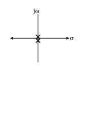
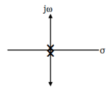
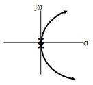
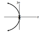
Explanation Locked!
Unlock this branch to view the explanation, track, bookmark and more.
Sign in to UnlockThe frequency of the clock signal applied to the rising edge triggered D flip-flop shown in figure is 10 kHz. The frequency of the signal available at Q is
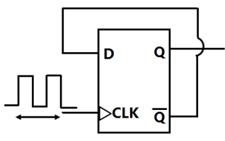
Explanation Locked!
Unlock this branch to view the explanation, track, bookmark and more.
Sign in to UnlockTwo in-phase 50 Hz sinusoidal waveform of unit amplitude are fed into channel 1 and channel 2 respectively of an oscilloscope. Assuming that the voltage scale, time scale and other settings are exactly the same for both the channels, what would be observed if the oscilloscope is operated in X-Y mode?
Explanation Locked!
Unlock this branch to view the explanation, track, bookmark and more.
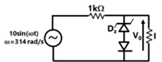
Sign in to UnlockThe cut-in voltage of both Zener diode and diode D shown in Figure is 0.7 V, while break down voltage of is 3.3 V and reverse breakdown voltage of D is 5V. The other parameters can be assumed to be the same as those of an ideal diode. The values of the peak output voltage are ........ ( Load Resistance = 1k Ohm )


Explanation Locked!
Unlock this branch to view the explanation, track, bookmark and more.
Sign in to UnlockThe open loop transfer function of a unity feedback system is given by

Find the angle and real axis intercept of the asymptotes, breakaway points and the imaginary axis crossing points, if any.
Explanation Locked!
Unlock this branch to view the explanation, track, bookmark and more.
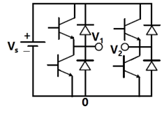
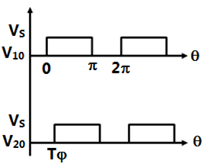
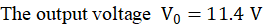
Sign in to UnlockFigure shows an inverter circuit with a dc source voltage. The semiconductor switches of the inverter are operated in such a manner that the pole voltages and are as shown in Figure. What is the RMS value of the pole-to-pole voltage?


Explanation Locked!
Unlock this branch to view the explanation, track, bookmark and more.
Sign in to UnlockThe ripple counter shown in figure is made up negative edge triggered J-K flips flops. The signal levels at J and K inputs of all the flip-flops are maintained at logic 1. Assume that all outputs are cleared just prior to applying the clock signal.

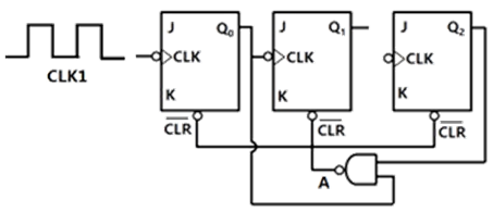
(a) Create a table of Q0, Q1, Q2 and A in the format given below for 10 successive input cycles of the clock CLK1.
(b) Determine the module number of the counter.
(c) Modify the circuit of given figure to create a module-6 counter using the same components used in the figure.
(a)
(b) Mod-8 counter
(c) The NAND gate input should be changed to instead of .
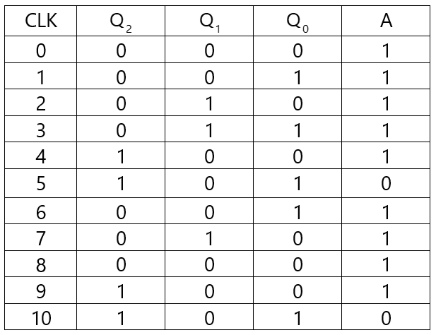


i.e. A

(a)
(b) Mod-6 counter
(c) The NAND gate input should be changed to instead of .
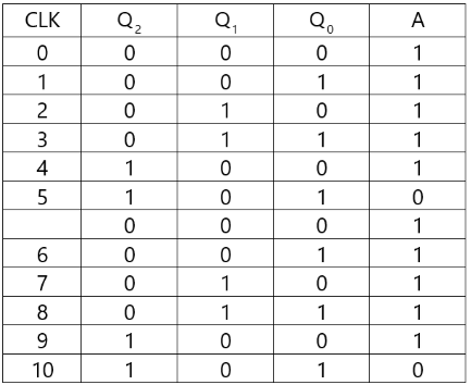
i.e. A
(a)
(b) Mod-5 counter
(c) The NAND gate input should be changed to instead of .
i.e. A
None
Explanation Locked!
Unlock this branch to view the explanation, track, bookmark and more.
Sign in to UnlockThe state transition matrix for the system X = AX & with initial state X(0) is


Laplace inverse of

Laplace inverse of

Explanation Locked!
Unlock this branch to view the explanation, track, bookmark and more.
Sign in to UnlockA step down chopper is operated in the continuous conduction mode in steady state with a constant duty ratio D. If is the magnitude of the dc output voltage and if is the magnitude of the dc input voltage, the ratio is given by


D
1− D


Explanation Locked!
Unlock this branch to view the explanation, track, bookmark and more.
Sign in to UnlockA power system consists of 2 areas (Area 1 and Area 2) connected by a single tie line (Figure). It is required to carry out a load flow study on this system. While entering the network data, the tie-line data (connectivity and parameters) is inadvertently left out. If the load flow program is run with this incomplete data
Explanation Locked!
Unlock this branch to view the explanation, track, bookmark and more.
Sign in to UnlockThe transfer function of the system described by with u as input and y as output is


Explanation Locked!
Unlock this branch to view the explanation, track, bookmark and more.
Sign in to UnlockIn the chopper circuit shown in Figure the input dc voltage has a constant value, the output voltage is assumed ripple-free. The switch S is operated with a switching time period T and a duty ratio D. what is the value of D at the boundary of continuous and discontinuous conduction of the inductor current ?


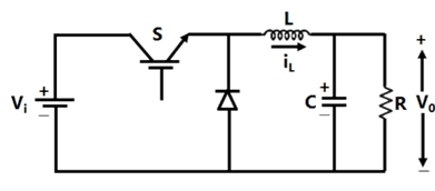


Explanation Locked!
Unlock this branch to view the explanation, track, bookmark and more.
Sign in to UnlockFor the system, which of the following statements is true?

Explanation Locked!
Unlock this branch to view the explanation, track, bookmark and more.
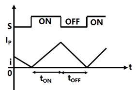
Sign in to UnlockIn Figure, the ideal switch S is switched on and off with a switching frequency f = 10 kHz. The switching time period is. The circuit is operated in steady state at the boundary of continuous and discontinuous conduction, so that the inductor current I is as shown in Figure. Find

(a) The on-time of the switch.

(b) The value of the peak current.


Explanation Locked!
Unlock this branch to view the explanation, track, bookmark and more.
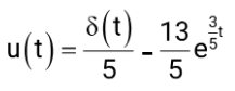
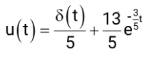
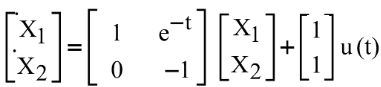
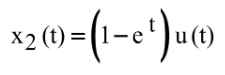
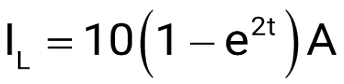
Sign in to UnlockFor the system

with u as unit impulse and with zero initial state, the output, y, becomes

2

4
2

4
Explanation Locked!
Unlock this branch to view the explanation, track, bookmark and more.
Sign in to UnlockObtain a state variable representation of the system governed by the differential equation, with the choice of state variables as

.
Also find , given that u(t) is a unit step function and.


State variable representation

State variable representation

Explanation Locked!
Unlock this branch to view the explanation, track, bookmark and more.
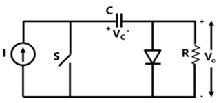
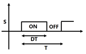
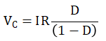
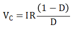
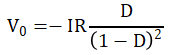
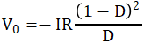
Sign in to UnlockIn the circuit shown in Figure, the source I is a dc current source. The switch S is operated with a time period T and a duty ratio D. You may assume that the capacitance C has a finite value which is large enough so that the voltage. has negligible ripple. Calculate the following under steady state conditions, in terms of D, I and R.

(a) The voltage, with the polarity shown in Figure.
(b) The average output voltage, with the polarity shown.
Explanation Locked!
Unlock this branch to view the explanation, track, bookmark and more.
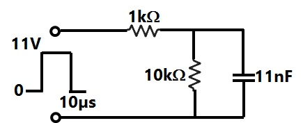
Sign in to UnlockAn 11 V pulse of 10 µs duration is applied to the circuit shown in Figure. Assuming that the capacitor is completely discharged prior to applying the pulse, the peak value of the capacitor voltage is
Explanation Locked!
Unlock this branch to view the explanation, track, bookmark and more.
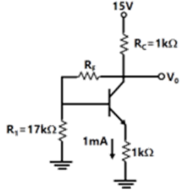
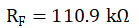
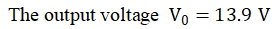
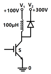
Sign in to UnlockFor the circuit shown in Figure, and . Determine


Explanation Locked!
Unlock this branch to view the explanation, track, bookmark and more.
Sign in to UnlockThe logic circuit used to generate the active low chip selects (CS) by an 8085 microprocessor to address a peripheral is shown in Figure. The peripheral will respond to addresses in the range.

Explanation Locked!
Unlock this branch to view the explanation, track, bookmark and more.
Sign in to UnlockThe semiconductor switch S in the circuit of Figure is operated at a frequency of 20 kHz and a duty ratio D=0.5. The circuit operates in the steady state. Calculate the power transferred from the dc voltage source to the dc voltage source.


Explanation Locked!
Unlock this branch to view the explanation, track, bookmark and more.
Sign in to UnlockThe determinant of the matrix
is:

Explanation Locked!
Unlock this branch to view the explanation, track, bookmark and more.
Sign in to UnlockIn the circuit shown in Figure, the switch is closed at time t = 0. The steady state value of the voltage is

Explanation Locked!
Unlock this branch to view the explanation, track, bookmark and more.
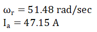
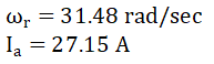
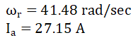
Sign in to UnlockA synchronous generator is to be connected to an infinite bus through a transmission line of reactance X = 0.2pu, as shown in Figure, the generator data is as follows:
x’ = 0.1pu, E’=1.0pu, H = 5MJ/MVA, mechanical power rad/sec.

All quantities are expressed on a common base.
The generator is initially running on open circuit with the frequency of the open circuit voltage slightly higher than that of the infinite bus. If at the instant of switch closure δ = 0 and , compute the maximum value of so that the generator pulls into synchronism.


Hint: Use the equation


Explanation Locked!
Unlock this branch to view the explanation, track, bookmark and more.
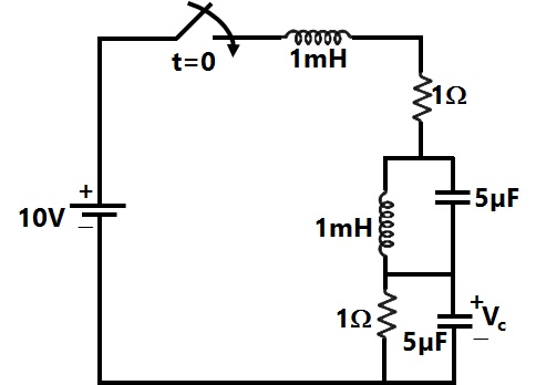
Sign in to UnlockA constant current source is supplying 10A to a circuit shown in Figure. The switch S, which is initially closed for a sufficiently long time, is suddenly opened. Obtain obtain the complete time response of the inductor current. What is the energy stored in L, a long time after the switch is opened?
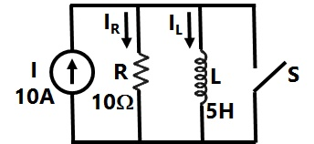
E=250J

E=250J
E=250J
E=350J
Explanation Locked!
Unlock this branch to view the explanation, track, bookmark and more.
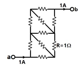
Sign in to UnlockIn the resistor network shown in Figure, all resistor values are 1Ω. A current of 1A passes from terminal a to terminal b, as shown in the figure. Calculate the voltage between terminals a and b. [Hint: You may exploit the symmetry of the circuit].
Explanation Locked!
Unlock this branch to view the explanation, track, bookmark and more.
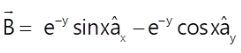
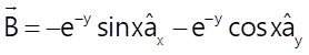
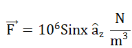
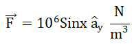
Sign in to UnlockThe magnetic vector potential in a region is defined by. An infinitely long conductor, having a cross section area,
and carrying a dc current, I = 5A in the y direction, passes through this region as shown in Figure.


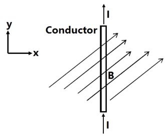
Determine the expression for (a) and (b) force density exerted on the conductor.


Explanation Locked!
Unlock this branch to view the explanation, track, bookmark and more.
Sign in to UnlockGiven a vector field, the divergence theorem states that


Explanation Locked!
Unlock this branch to view the explanation, track, bookmark and more.
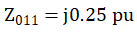
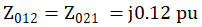
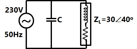
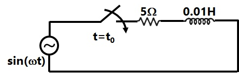
Sign in to UnlockA generator is connected to a transformer which feeds another transformer through a short feeder (see Figure). The zero sequence impedance values are expressed in pu on a common base and are indicated in Figure. The Thevenin’s equivalent zero sequence impedance at point B is
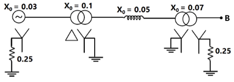
Explanation Locked!
Unlock this branch to view the explanation, track, bookmark and more.
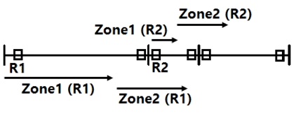
Sign in to UnlockConsider the problem of relay co-ordination for the distance relays R1 and R2 on adjacent lines of a transmission system (Figure). The Zone 1 and Zone 2 settings for both the relays are indicated on the diagram. Which of the following indicates the correct time setting for the Zone 2 of relays R1 and R2


Explanation Locked!
Unlock this branch to view the explanation, track, bookmark and more.
Sign in to UnlockTwo transposed 3 phase lines run parallel to each other, the equation describing the voltage drop in both lines is given below.

Compute the self and mutual zero sequence impedances of this system i.e. compute in the following equations


Where are the zero sequence voltage drops and currents for the two lines respectively

Explanation Locked!
Unlock this branch to view the explanation, track, bookmark and more.
Sign in to UnlockIn the single phase diode bridge rectifier shown in figure, the load resistor is R = 50Ω.
The source voltage is v=200sin(ωt), where ω=2π × 50 radians per second. The power dissipated in the load resistor R is


400 W
800 W
Explanation Locked!
Unlock this branch to view the explanation, track, bookmark and more.
Sign in to UnlockA six pulse thyristor rectifier bridge is connected to a balanced 50 Hz three phase ac source. Assuming that the dc output current of the rectifier is constant, the lowest frequency harmonic component in the ac source line current is
Explanation Locked!
Unlock this branch to view the explanation, track, bookmark and more.
Sign in to UnlockA three phase thyristor bridge rectifier is used in a HVDC link. The firing angle α (as measured from the point of natural commutation) is constrained to lie between 5° and 30°. If the dc side current and ac side voltage magnitudes are constant, which of the following statements is true (neglect harmonics in the ac side currents and commutation overlap in your analysis)
Explanation Locked!
Unlock this branch to view the explanation, track, bookmark and more.
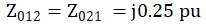
Sign in to UnlockIn the circuit shown in Figure, what value of C will cause a unity power factor at the ac source?
Explanation Locked!
Unlock this branch to view the explanation, track, bookmark and more.
Sign in to UnlockA series R-L-C circuit has R = 50Ω, L = 100 μH and C = 1 μF. the lower half power frequency of the circuit is
Explanation Locked!
Unlock this branch to view the explanation, track, bookmark and more.
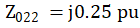
Sign in to UnlockConsider the circuit shown in Figure. If the frequency of the source is 50 Hz, then a value of which results in a transient free response is

Explanation Locked!
Unlock this branch to view the explanation, track, bookmark and more.
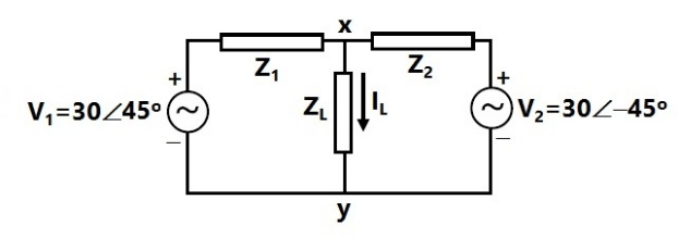
Sign in to UnlockAn electrical network is fed by two ac sources, as shown Figure. Given that , and . Obtain the Thevenin equivalent circuit (Thevenin voltage and impedance) across terminals x and y, and determine the current through the load .


Explanation Locked!
Unlock this branch to view the explanation, track, bookmark and more.
Sign in to UnlockThe flux per pole in a synchronous motor with the field circuit ON and the stator disconnected from the supply is found to be 25mWb. When the stator is connected to the rated supply with the field excitation unchanged, the flux per pole in the machine is found to be 20mWb while the motor is running on no load.
Assuming no load losses to be zero, the no load current down by the motor from the supply
Explanation Locked!
Unlock this branch to view the explanation, track, bookmark and more.
Sign in to UnlockThe line-to-line input voltage to the 3 phase, 50 Hz, ac circuit shown in figure is 100 V rms. Assuming that the phase sequence is RYB, the watt-meters would read.
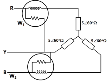
= 886 W and = 886 W


= 500 W and = 500 W
= 0 W and = 1000 W
= 250 W and = 750 W
Explanation Locked!
Unlock this branch to view the explanation, track, bookmark and more.
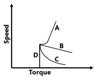
Sign in to UnlockA dc series motor fed from rated supply voltage is overloaded and its magnetic circuit is saturated. The torque-speed characteristic of this motor will be approximately represented by which curve of Figure?
Explanation Locked!
Unlock this branch to view the explanation, track, bookmark and more.
Sign in to UnlockA 415 V, 2 poles, 3 phases, 50 Hz, star connected, non-salient pole synchronous motor has synchronous reactance of 2 Ω per phase and negligible stator resistance. At a particular field excitation, it draws 20 A at unity power factor from a 415 V, 3 phase, 50 Hz supply. The mechanical load on the motor is now increased till the stator current is equal to 50A. The field excitation remains unchanged. Determine:
(a) The per phase open circuit voltage

(b) The developed power for the new operating condition and corresponding power factor
Explanation Locked!
Unlock this branch to view the explanation, track, bookmark and more.
Sign in to UnlockA 200 V, 2000 rpm, 10A, separately excited dc motor has an armature resistance of 2Ω. Rated dc voltage is applied to both the armature and field winding of the motor. If the armature draws 5A from the source, the torque developed by the motor is
Explanation Locked!
Unlock this branch to view the explanation, track, bookmark and more.
Sign in to UnlockA first order, low pass filter is given with and . What is the frequency at which the gain of the voltage transfer function of the filter is 0.25?


Explanation Locked!
Unlock this branch to view the explanation, track, bookmark and more.
Sign in to UnlockIf a 400V, 50 Hz, star connected, 3 phase squirrel cage induction motor is operated from a 400 V, 75 Hz supply, the torque that the motor can now provide while drawing rated current from the supply?
Explanation Locked!
Unlock this branch to view the explanation, track, bookmark and more.
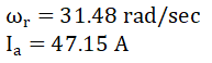
Sign in to UnlockA 230V, 250 rpm, 100A separately excited dc motor has an armature resistance of 0.5Ω, the motor is connected to 230V dc supply and rated dc voltage is applied to the field winding. It is driving a load whose torque speed characteristic is given by 500 − 10ω, where ω is the rotational speed expressed in rad/sec and is the load torque in Nm. Find the steady state speed at which the motor will drive the load and the rated armature current drawn by it from the source. Neglect the rotational losses of the machine.


Explanation Locked!
Unlock this branch to view the explanation, track, bookmark and more.
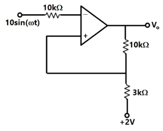
Sign in to UnlockThe output voltage of the Schmitt trigger shown in Figure swings between +15V and –15V. Assume that the operational amplifier is ideal. The output will change from +15V to –15V when the instantaneous value of the input sine wave is

Explanation Locked!
Unlock this branch to view the explanation, track, bookmark and more.
Sign in to UnlockThe rotor of a three phase, 5 kW, 400V, 50 Hz, slip ring induction motor is wound for 6 poles while its stator is wound for 4 poles. The approximate average no load steady state speed when this motor is connected to 400V, 50 Hz supply is
Explanation Locked!
Unlock this branch to view the explanation, track, bookmark and more.
Sign in to UnlockDetermine the transfer function for the RC network shown in Figure (a). This network is used as a feedback circuit in an oscillator circuit shown in Figure (b) to generate sinusoidal oscillations. Assuming that the operational amplifier is ideal, determine for generating these oscillations. Also, determine the oscillation frequency if and C =100pF.


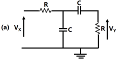
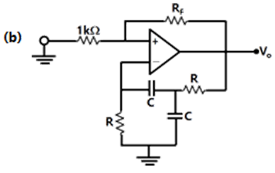
Explanation Locked!
Unlock this branch to view the explanation, track, bookmark and more.
Sign in to UnlockA 440 V, 50 Hz, 6 poles and 960 rpm star connected induction machine has the following per phase parameters referred to the stator:

The magnetizing reactance is very high and is neglected. The machine is connected to the 440V, 50 Hz supply and a certain mechanical load is coupled to it. It is found that the magnitude of the stator current is equal to the rated current of the machine but the machine is running at a speed higher than its rated speed. Find the speed at which the machine is running. Also find the torque developed by the machine.
Explanation Locked!
Unlock this branch to view the explanation, track, bookmark and more.
Sign in to UnlockA 1 kVA, 230V/100V, single phase, 50 Hz transformer having negligible winding resistance and leakage inductance is operating under saturation, while 250 V, 50 Hz sinusoidal supply is connected to the high voltage winding. A resistive load is connected to the low voltage winding which draws rated current. Which one of the following quantities will not be sinusoidal?
Explanation Locked!
Unlock this branch to view the explanation, track, bookmark and more.
Sign in to UnlockA 400V/200V/200V, 50 Hz three winding transformer is connected as shown in Figure. The reading of the voltmeter, V, will be
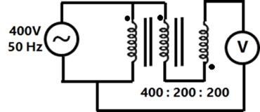
Explanation Locked!
Unlock this branch to view the explanation, track, bookmark and more.
Sign in to UnlockA single phase 6300kVA, 50 Hz, 3300V/400V distribution transformer is connected between two 50 Hz supply systems, A and B as shown in Figure, the transformer has 12 and 99 turns in the low and high voltage windings respectively. The magnetizing reactance of the transformer referred to the high voltage side is 500Ω. The leakage reactance of the high and low voltage windings are 1.0Ω and 0.012Ω respectively. Neglect the winding resistance and core losses of the transformer. The Thevenin voltage of system A is 3300V while that of system B is 400 V, the short circuit reactance of systems A and B are 0.5Ω and 0.010 Ω respectively. If no power is transferred between A and B, so that the two system voltages are in phase, find the magnetizing ampere turns of the transformer.

Explanation Locked!
Unlock this branch to view the explanation, track, bookmark and more.
Sign in to UnlockConsider a long, two-wire line composed of solid round conductors. The radius of both conductors is 0.25 cm and the distance between their centers is 1m. If this distance is doubled, then the inductance per unit length
Explanation Locked!
Unlock this branch to view the explanation, track, bookmark and more.
Sign in to UnlockConsider a power system with three identical generators. The transmission losses are negligible. One generator () has a speed governor which maintains its speed constant at the rated value, while the other generators (and ) have governors with a drop of 5%.If the load of the system is increased, then in steady state.


Generation of and is increased equally while generation of is unchanged.
Generation of alone is increased while generation of and is unchanged.
Generation of , and is increased equally.
Generation of , and is increased in the ratio 0.5:0.25:0.25.
Explanation Locked!
Unlock this branch to view the explanation, track, bookmark and more.
Sign in to UnlockA long wire composed of a smooth round conductor runs above and parallel to the ground (assumed to be a large conducting plane). A high voltage exists between the conductor and the ground. The maximum electric stress occurs at
Explanation Locked!
Unlock this branch to view the explanation, track, bookmark and more.
Sign in to UnlockA transmission line has a total series reactance of 0.2 pu. Reactive power compensation is applied at the midpoint of the line and it is controlled such that the midpoint voltage of the transmission line is always maintained at 0.98 pu. If voltage at both ends of the line are maintained at 1.0 pu, then the steady state power transfer limit of the transmission line is
Explanation Locked!
Unlock this branch to view the explanation, track, bookmark and more.
Sign in to UnlockA long lossless transmission line has a unity power factor (UPF) load at the receiving end and an ac voltage source at the sending end (Figure). The parameters of the transmission line are as follows:
Characteristic impedance , propagation constant , and length. The equation relating sending and receiving end questions is


Compute the maximum power that can be transferred to the UPF load at the receiving end if .


Explanation Locked!
Unlock this branch to view the explanation, track, bookmark and more.
Sign in to Unlock