
A reading of 120 is obtained when a standard inductor was connected in the circuit of a Q-meter and the variable capacitor is adjusted to a value of 300pF. A lossless capacitor of unknown value is then connected in parallel with the variable capacitor and the same reading was obtained when the variable capacitor is readjusted to a value of 200pF. The value of in pF is

Explanation Locked!
Unlock this branch to view the explanation, track, bookmark and more.
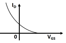
Sign in to UnlockThe variation of drain current with gate-to-source voltage ( characteristic) of a MOSFET is shown in Figure. The MOSFET is

Explanation Locked!
Unlock this branch to view the explanation, track, bookmark and more.
Sign in to UnlockFor the n-channel enhancement MOSFET shown in Figure, the threshold voltage . The drain current of the MOSFET is 4 mA when the drain resistance is . If the value of is increased to , drain current will become


Explanation Locked!
Unlock this branch to view the explanation, track, bookmark and more.
Sign in to UnlockIncremental fuel costs (in some appropriate unit) for a power plant consisting of three generating units are


Where is the power in MW generated by unit i, for i = 1, 2 and 3. Assume that all the three units are operating all the time. Minimum and maximum loads on each unit are 50 MW and 300 MW respectively. If the plant is operating on economic load dispatch to supply the total power demand of 700 MW, the power generated by each unit is ____________________.

= 242.86 MW; = 157.14 MW; and = 300 MW


= 157.14 MW; = 242.86 MW; and = 300 MW
= 300.0 MW; = 300.0 MW; and = 100 MW
= 233.3 MW; = 233.3 MW; and = 233.4 MW
Explanation Locked!
Unlock this branch to view the explanation, track, bookmark and more.
Sign in to UnlockGroup I lists different applications and Group II lists the motors for these applications. Match the application with the most suitable motor and choose the right combination among the choices given thereafter
Group I | Group II |
P. Food mixer | 1. Permanent magnet dc motor |
Q. Cassette tape recorder | 2. Single phase induction motor |
R. Domestic water pump | 3. Universal motor |
S. Escalator | 4. Three phase induction motor |
5. DC series motor | |
6. Stepper motor |
Explanation Locked!
Unlock this branch to view the explanation, track, bookmark and more.
Sign in to UnlockThe items in Group I represent the various types of measurements to be made with a reasonable accuracy using a suitable bridge. The items in Group II represent the various bridges available for this purpose. Select the correct choice of the item in Group II for the corresponding item in Group I from the following
Group I | Group II |
P Resistance in the milli-Ohm range | 1 Wheatstone Bridge |
Q Low values of Capacitance | 2 Kelvin Double Bridge |
R Comparison of resistances which are nearly equal | 3 Schering Bridge |
S Inductance of a coil with a large time constant | 4 Wien’s Bridge |
5 Hay’s Bridge | |
6 Carey-Foster Bridge |
Explanation Locked!
Unlock this branch to view the explanation, track, bookmark and more.
Sign in to UnlockA lead compensator used for a closed loop controller has the following transfer function. For such a lead compensator

Explanation Locked!
Unlock this branch to view the explanation, track, bookmark and more.
Sign in to UnlockA 500 A/5 A, 50 Hz current transformer has a bar primary. The secondary burden is a pure resistance of 1 Ω and it draws a current of 5 A. If the magnetic core requires 250 AT for magnetization, the percentage ratio error is
Explanation Locked!
Unlock this branch to view the explanation, track, bookmark and more.
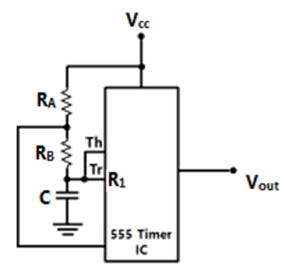
Sign in to UnlockThe circuit of Figure shows a 555 Timer IC connected as an Astable multi-vibrator. The value of the capacitor C is 10nF. The values of the resistors and for a frequency of 10kHz and a duty cycle of 0.75 for the output voltage waveform are


Explanation Locked!
Unlock this branch to view the explanation, track, bookmark and more.
Sign in to UnlockThe Boolean expression
can be simplified to


Explanation Locked!
Unlock this branch to view the explanation, track, bookmark and more.
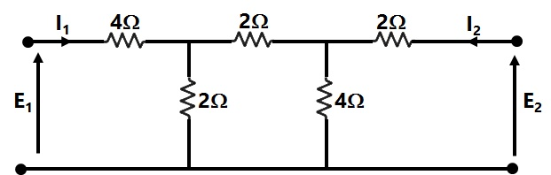
Sign in to UnlockThe h-parameters for a two-port network are defined by.

For the two-port network shown in Figure, the value of is given by

Explanation Locked!
Unlock this branch to view the explanation, track, bookmark and more.
Sign in to UnlockFigure shows a 4 to 1 MUX to be used to implement the sum S of a 1-bit full adder with input bits P and Q and the carry input. Which of the following combinations of inputs to and of the MUX will realize the sum S?


Explanation Locked!
Unlock this branch to view the explanation, track, bookmark and more.
Sign in to UnlockGroup II represents the figures obtained on a CRO screen when the voltage signals and are given to its X and Y plates respectively and Φ is changed. Choose the correct value of Φ from Group I to match with the corresponding figure of Group II


Group I
P. Φ = 0 Q. Φ =

R. S.


Group II


Explanation Locked!
Unlock this branch to view the explanation, track, bookmark and more.
Sign in to UnlockA voltage signal 10 sinωt is applied to the circuit with ideal diodes, as shown in Figure. The maximum and minimum values of the output waveform of the circuit are respectively 10kΩ


Explanation Locked!
Unlock this branch to view the explanation, track, bookmark and more.
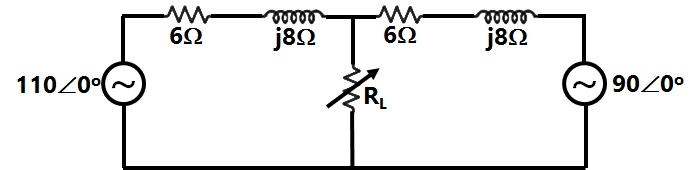
Sign in to UnlockTwo ac sources feed a common variable resistive load as shown in Figure. Under the maximum power transfer condition, the power absorbed by the load resistance RL is
Explanation Locked!
Unlock this branch to view the explanation, track, bookmark and more.
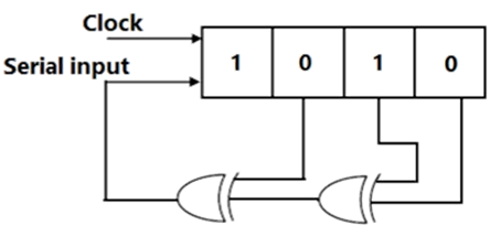
Sign in to UnlockThe shift register shown in Figure is initially loaded with the bit pattern 1010. Subsequently the shift register is clocked, and with each clock pulse the pattern gets shifted by one bit position to the right. With each shift, the bit at the serial input is pushed to the left most position (MSB). After how many clock pulses will the content of the shift register become 1010 again?
Explanation Locked!
Unlock this branch to view the explanation, track, bookmark and more.
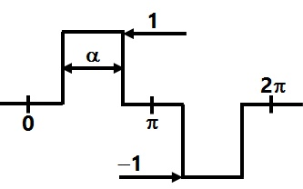
Sign in to UnlockAn inverter has a periodic output voltage with the output waveform as shown in Fig. When the conduction angle α=120°, the RMS fundamental component of the output voltage is
Explanation Locked!
Unlock this branch to view the explanation, track, bookmark and more.
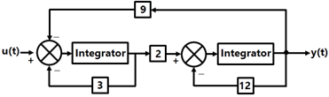
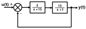
Sign in to UnlockThe block diagram of a control system is shown in Figure. The transfer function of the system is


Explanation Locked!
Unlock this branch to view the explanation, track, bookmark and more.
Sign in to UnlockA power system consists of 300 buses out of which 20 buses are generator buses, 25 buses are the ones with reactive power support and 15 buses are the ones with fixed shunt capacitors. All the other buses are load buses. It is proposed to perform a load flow analysis for the system using Newton-Raphson method. The size of the Newton-Raphson Jacobian matrix is
Explanation Locked!
Unlock this branch to view the explanation, track, bookmark and more.
Sign in to UnlockAn X-Y flip flop, whose Characteristic Table is given below is to be implemented using a J-K flip flop

This can be done by making


Explanation Locked!
Unlock this branch to view the explanation, track, bookmark and more.
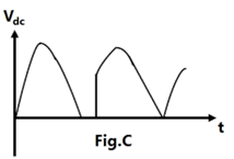
Sign in to UnlockWith reference to the output waveform given in Figure, the output of the converter will be free from 5th harmonic when


Explanation Locked!
Unlock this branch to view the explanation, track, bookmark and more.
Sign in to UnlockThe loop gain GH of a closed system is given by the following expression

The value of K for which the system just becomes unstable is
Explanation Locked!
Unlock this branch to view the explanation, track, bookmark and more.
Sign in to UnlockThe bus impedance matrix of a 4-bus power system is given by

A branch having an impedance of j0.2Ω is connected between bus 2 and the reference. Then the values of and of the bus impedance matrix of the modified network are respectively.


Explanation Locked!
Unlock this branch to view the explanation, track, bookmark and more.
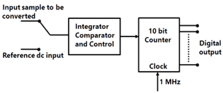
Sign in to UnlockThe simplified block diagram of a 10-bit A/D converter of dual slope integrator type is shown in figure. The 10-bit counter at the output is clocked by a 1MHz clock. Assuming negligible timing overhead for the control logic, the maximum frequency of the analog signal that can be converted using this A/D converter is approximately
Explanation Locked!
Unlock this branch to view the explanation, track, bookmark and more.
Sign in to UnlockA second order system starts with an initial condition of without any external input. The state transition matrix for the system is given by. The state of the system at the end of 1 second is given by


Explanation Locked!
Unlock this branch to view the explanation, track, bookmark and more.
Sign in to UnlockWhen a program is being executed in an 8085 microprocessor, its Program Counter contains
Explanation Locked!
Unlock this branch to view the explanation, track, bookmark and more.
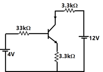
Sign in to UnlockIn the circuit of Figure, assume that the transistor has . The value of collector current of the transistor is approximately


Explanation Locked!
Unlock this branch to view the explanation, track, bookmark and more.
Sign in to UnlockThe following equation defines a separately excited dc motor in the form of a differential equation

The above equation may be organized in the state-space form as follows

Where the P matrix is given by


Explanation Locked!
Unlock this branch to view the explanation, track, bookmark and more.
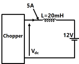
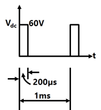
Sign in to UnlockA chopper is employed to charge a battery as shown in Figure. The charging current is 5A. The duty ratio is 0.2. The chopper output voltage is also shown in Figure. The peak-to-peak ripple current in the charging current is
Explanation Locked!
Unlock this branch to view the explanation, track, bookmark and more.
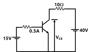
Sign in to UnlockIn the circuit shown in Figure, the current gain (β) of the ideal transistor is 10. The operating point of the transistor is

Explanation Locked!
Unlock this branch to view the explanation, track, bookmark and more.
Sign in to UnlockA memory system has a total of 8 memory chips, each with 12 address lines and 4 data lines. The total size of the memory system is
Explanation Locked!
Unlock this branch to view the explanation, track, bookmark and more.
Sign in to UnlockThe asymptotic Bode plot of the transfer function is given in figure. The error in phase angle and dB gain at a frequency of ω=0.5 a are respectively.

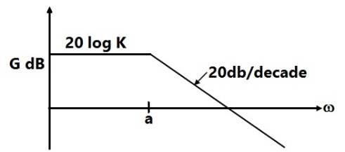
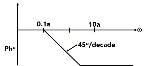
Explanation Locked!
Unlock this branch to view the explanation, track, bookmark and more.
Sign in to UnlockIn the circuit shown in Figure, the switch S is closed at time t = 0. The voltage across the inductance at
, is

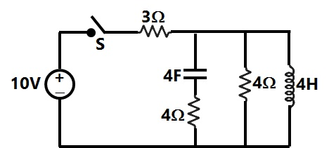
Explanation Locked!
Unlock this branch to view the explanation, track, bookmark and more.
Sign in to UnlockThe following program is written for an 8085 microprocessor to add two bytes located at memory addresses 1FFE and 1FFF
LXI H, 1FFE
MOV B, M
INR L
MOV A, M
ADD B
INR L
MOV M, A
XOR A
On completion of the execution of the program, the result of addition is
Explanation Locked!
Unlock this branch to view the explanation, track, bookmark and more.
Sign in to UnlockA round rotor generator with internal voltage and X = 1.1 p.u. is connected to a round rotor synchronous motor with internal voltage and X = 1.2 p.u. The reactance of the line connecting the generator to the motor is 0.5 p.u. when the generator supplies 0.5 p.u. power, the rotor angle difference between the machines will be


Explanation Locked!
Unlock this branch to view the explanation, track, bookmark and more.
Sign in to UnlockA generator delivers power of 1.0 p.u. to an infinite bus through a purely reactive network. The maximum power that could be delivered by the generator is 2.0 p.u. A three phase fault occurs at the terminals of the generator which reduces the generator output to zero. The fault is cleared after second. The original network is then restored. The maximum swing of the rotor angle is found to be electrical degree. Then the rotor angle in electrical degrees at t = is


Explanation Locked!
Unlock this branch to view the explanation, track, bookmark and more.
Sign in to UnlockFigure shows the waveform of the current passing through an inductor of resistance 1Ω and inductance 2 H. The energy absorbed by the inductor in the first four seconds is
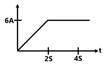
Explanation Locked!
Unlock this branch to view the explanation, track, bookmark and more.
Sign in to UnlockTwo conductors are carrying forward and return current of +I and –I as shown in Figure. The magnetic field intensity at point P is

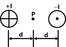


Explanation Locked!
Unlock this branch to view the explanation, track, bookmark and more.
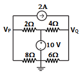
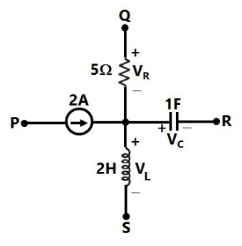
Sign in to UnlockIn Figure, the potential difference between points P and Q is
Explanation Locked!
Unlock this branch to view the explanation, track, bookmark and more.
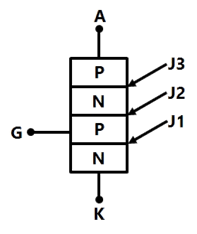
Sign in to UnlockFigure shows a thyristor with the standard terminations of anode (A), cathode (K), gate (G) and the different junctions named J1, J2 and J3. When the thyristor is turned on and conducting
Explanation Locked!
Unlock this branch to view the explanation, track, bookmark and more.
Sign in to UnlockTwo infinite strips of width w m in x direction as shown in Figure, are carrying forward and return currents of +I and –I in the z direction. The strips are separated by a distance of x m. The inductance per unit length of the configuration is measured to be L H/m. If the distance of separation between the strips is now reduced to , the inductance per unit length of the configuration


2L H/m


4L H/m
Explanation Locked!
Unlock this branch to view the explanation, track, bookmark and more.
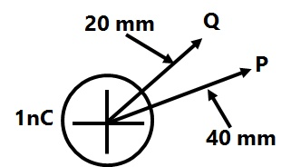
Sign in to UnlockA point charge of +1nC is placed in a space with a permittivity of as shown in Figure. The potential difference between two points P and Q at distances of 40 mm and 20 mm respectively from the point charge is


Explanation Locked!
Unlock this branch to view the explanation, track, bookmark and more.
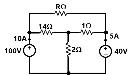
Sign in to UnlockIn Figure the value of R is
Explanation Locked!
Unlock this branch to view the explanation, track, bookmark and more.
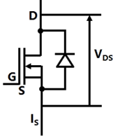
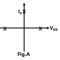
Sign in to UnlockFigure shown a MOSFET with an integral body diode. It is employed as a power switching device in the ON and OFF states through appropriate control. The ON and OFF states of the switch are given on the plane by

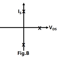
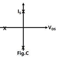
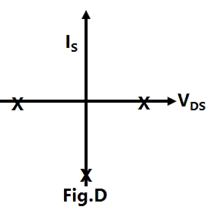
Explanation Locked!
Unlock this branch to view the explanation, track, bookmark and more.
Sign in to UnlockA parallel plate capacitor has an electrode area of , with a spacing of 0.1 mm between the electrodes. The dielectric between the plates is air with a permittivity of . The charge on the capacitor is 100 V. The stored energy in the capacitor is

Explanation Locked!
Unlock this branch to view the explanation, track, bookmark and more.
Sign in to UnlockA composite parallel plate capacitor is made up of two different dielectric materials with different thickness ( and ) as shown in Figure. The two different dielectric materials are separated by a conducting foil F. The voltage of the conducting foil is


Explanation Locked!
Unlock this branch to view the explanation, track, bookmark and more.
Sign in to UnlockA 20-MVA, 6.6-kV, 3-phase alternator is connected to a 3-phase transmission line. The per unit positive sequence, negative sequence and zero sequence impedances of the alternator are j0.1, and j0.04 respectively. The neutral of the alternator is connected to ground through an inductive reactor of j0.05 p.u. The per unit positive, negative and zero sequence impedances of the transmission line are j0.1 and j0.3 respectively. All per unit values are based on the machine ratings. A solid ground fault occurs at one phase of the far end of the transmission line. The voltage of the alternator neutral with respect to ground during the fault is
Explanation Locked!
Unlock this branch to view the explanation, track, bookmark and more.
Sign in to UnlockThe interrupting time of a circuit breaker is the period between the instant of
Explanation Locked!
Unlock this branch to view the explanation, track, bookmark and more.
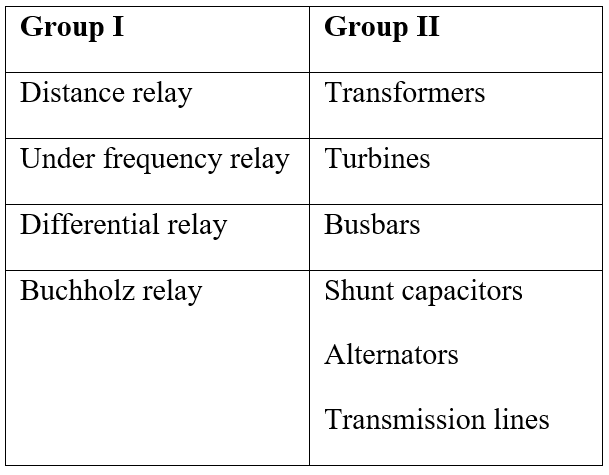
Sign in to UnlockA list of relays and the power system components protected by the relays are given in Group I and Group II respectively. Choose the correct match from the four choices given below:
Explanation Locked!
Unlock this branch to view the explanation, track, bookmark and more.
Sign in to UnlockA control system is defined by the following mathematical relationship

The response of the system as t →∞ is
Explanation Locked!
Unlock this branch to view the explanation, track, bookmark and more.
Sign in to UnlockA three-phase alternator generating unbalanced voltages is connected to an unbalanced load through a 3-phase transmission line as shown in Figure, the neutral of the alternator and the star point of the load are solidly grounded. The phase voltages of the alternator are 10∠0°, 10∠−90°V, 10∠120°V. The positive sequence component of the load current is


Explanation Locked!
Unlock this branch to view the explanation, track, bookmark and more.
Sign in to UnlockA control system with certain excitation is governed by the following mathematical equation

The natural time constants of the response of the system are
Explanation Locked!
Unlock this branch to view the explanation, track, bookmark and more.
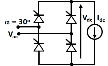
Sign in to UnlockA fully controlled natural commuted 3-phase bridge rectifier is operating with a firing angle α=30°. The peak to peak voltage ripple expressed as a ratio of the peak output dc voltage at the output of the converter bridge is
0.5


Explanation Locked!
Unlock this branch to view the explanation, track, bookmark and more.
Sign in to UnlockThe block diagram shown in Figure gives a unity feedback closed loop control system. The steady state error in the response of the above system to unit step input is
Explanation Locked!
Unlock this branch to view the explanation, track, bookmark and more.
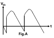
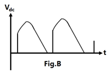
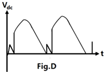
Sign in to UnlockA phase controlled half controlled single phase converter is
shown in Figure. The control angle
α = 30°. The output dc voltage wave shape will be a s shown in
Explanation Locked!
Unlock this branch to view the explanation, track, bookmark and more.
Sign in to UnlockThe roots of the closed loop characteristic equation of the system shown in above figure are
Explanation Locked!
Unlock this branch to view the explanation, track, bookmark and more.
Sign in to UnlockA segment of a circuit is shown in Figure. , . The voltage is given by


Explanation Locked!
Unlock this branch to view the explanation, track, bookmark and more.
Sign in to UnlockIn the Figure.
.
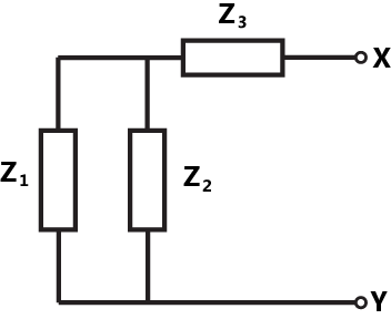

The thevenin impedance seen from X-Y is
Explanation Locked!
Unlock this branch to view the explanation, track, bookmark and more.
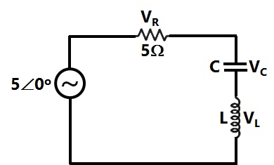
Sign in to UnlockIn the circuit of Figure, the magnitudes of and are twice that of . The inductance of the coil is


Explanation Locked!
Unlock this branch to view the explanation, track, bookmark and more.
Sign in to UnlockA Manganin swamp resistance is connected in series with a moving coil ammeter consisting of a milli-ammeter and a suitable shunt in order to
Explanation Locked!
Unlock this branch to view the explanation, track, bookmark and more.
Sign in to UnlockA stand-alone engine driven Synchronous generator is feeding a partly inductive load. A capacitor is now connected across the load to completely nullify the inductive current. For this operating condition.
Explanation Locked!
Unlock this branch to view the explanation, track, bookmark and more.
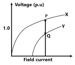
Sign in to UnlockCurves X and Y in Figure denote open circuit and full-load zero power factor (zpf) characteristics of asynchronous generator. Q is a point on the zpf characteristics at 1.0 p.u. voltage. The vertical distance PQ in Figure gives the voltage drop across
Explanation Locked!
Unlock this branch to view the explanation, track, bookmark and more.
Sign in to UnlockThe effect of stray magnetic fields on the actuating torque of a portable instrument is maximum when the operating field of the instrument and the stray fields are
Explanation Locked!
Unlock this branch to view the explanation, track, bookmark and more.
Sign in to UnlockA 4-pole, 3-phase, double layer winding is housed in a 36-slot stator for an ac machine with 60° phase spread. Coil span is 7 slot pitches. Number of slots in which top and bottom layers belong to different phases is
Explanation Locked!
Unlock this branch to view the explanation, track, bookmark and more.
Sign in to UnlockThe speed/torque regimes in a dc motor and the control methods suitable for the same are given respectively in Group II and Group I
Group I | Group II |
P Field Control | 1 Below base speed |
Q Armature Control | 2 Above base speed |
3 Above base torque | |
4 Below base torque |
Explanation Locked!
Unlock this branch to view the explanation, track, bookmark and more.
Sign in to UnlockA rectifier type ac voltmeter consists of a series resistance an ideal full wave rectifier bridge and a PMMC instrument as shown in Figure. The internal resistance of the instrument is 100 Ω and a full-scale deflection is produced by a dc current of 1mA. The value of required to obtain full scale deflection with an AC voltage of 100 V (RMS) applied to the input terminals is


Explanation Locked!
Unlock this branch to view the explanation, track, bookmark and more.
Sign in to UnlockTo conduct load test on a dc shunt motor, it is coupled to a generator which is identical to the motor. The field of the generator is also connected to the same supply source as the motor. The armature of the generator is connected to a load resistance. The armature resistance is 0.02 p.u. armature reaction and mechanical losses can be neglected. With rated voltage across the motor, the load resistance across the generator is adjusted to obtain rated armature current in both motor and generator. The p.u. value of this load resistance is
Explanation Locked!
Unlock this branch to view the explanation, track, bookmark and more.
Sign in to UnlockA wattmeter reads 400 W when its current coil is connected in the R phase and its pressure coil is connected between this phase and the neutral of asymmetrical 3-phase system supplying a balanced star connected 0.8p.f. inductive load. The phase sequence is RYB. What will be the reading of this wattmeter if its pressure coil alone is reconnected between the B and Y phases all other connections remaining as before
Explanation Locked!
Unlock this branch to view the explanation, track, bookmark and more.
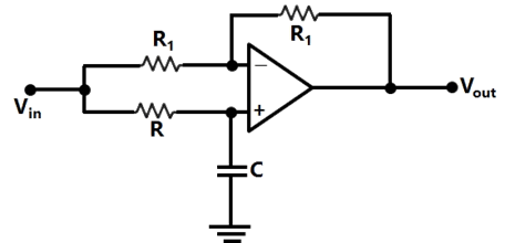
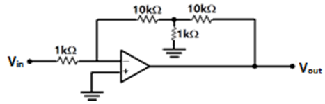
Sign in to UnlockFor the circuit of Figure with an ideal operational amplifier, the maximum phase shift of the output with reference to the input is


Explanation Locked!
Unlock this branch to view the explanation, track, bookmark and more.
Sign in to UnlockAn ac induction motor is used for a speed control application. It is driven from an inverter with a constant V/f control. The motor nameplate details are as follows
V: 415 V Ph: 3 f: 50Hz N: 2850 rpm
The motor is run with the inverter output frequency set at 40 Hz, and with half the rated slip. The running speed of the motor is
Explanation Locked!
Unlock this branch to view the explanation, track, bookmark and more.
Sign in to UnlockThe inductance of a certain moving-iron ammeter is expressed as , where θ is the deflection in radians from the zero position. The control spring torque in Nm/radian, the deflection of the pointer in radian when the meter carries a current of 5A, is


Explanation Locked!
Unlock this branch to view the explanation, track, bookmark and more.
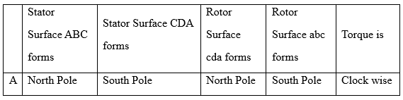
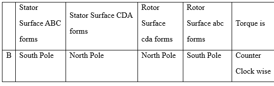
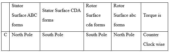
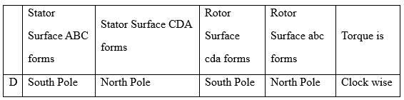
Sign in to UnlockWhen Stator and Rotor windings of a 2-pole rotating electrical machine are excited, each would produce a sinusoidal MMF distribution in the air gap with peak values and respectively. The rotor MMF lags stator MMF by a space angle δ at any instant as shown in Figure. Thus, half of stator and rotor surfaces will form one pole with the other half forming the second pole. Further, the direction of torque acting on the rotor can be clockwise or counter-clockwise.


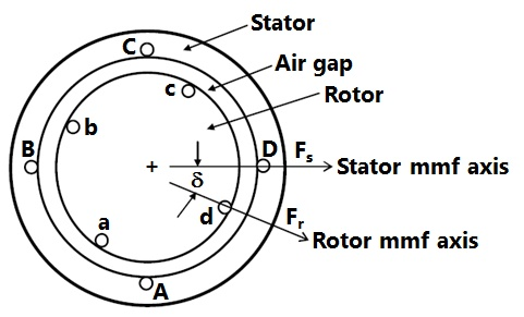
The following Table gives four sets of statements regarding poles and torque. Select the correct set corresponding to the MMF axis as shown in Figure
Explanation Locked!
Unlock this branch to view the explanation, track, bookmark and more.
Sign in to UnlockAssuming the operational amplifier to be ideal, the gain for the circuit shown in Figure is

Explanation Locked!
Unlock this branch to view the explanation, track, bookmark and more.
Sign in to UnlockThe voltage flux adjustment of a certain 1-phase 220 V induction watt hour meter is altered so that the phase angle between the applied voltage and the flux due to it is 85° (instead of 90°). The errors introduced in the reading of this meter when the current is 5A at power factors of unity and 0.5 lagging are respectively.
Explanation Locked!
Unlock this branch to view the explanation, track, bookmark and more.
Sign in to UnlockNo-load test on a 3-phase induction motor was conducted at different supply voltages and a plot of input power versus voltage was drawn. This curve was extrapolated to intersect the y-axis. This intersection point yields
Explanation Locked!
Unlock this branch to view the explanation, track, bookmark and more.
Sign in to UnlockA DC series motor driving an electric train faces a constant power load. It is running at rated speed and rated voltage. If the speed has to be brought down to 0.25 p.u. the supply voltage has to be approximately brought down to
Explanation Locked!
Unlock this branch to view the explanation, track, bookmark and more.
Sign in to UnlockFollowing are some of the properties of rotating electrical machines
P Stator winding current is dc, rotor-winding current is ac
Q Stator winding current is ac, rotor-winding current is dc
R Stator winding current is ac, rotor-winding current is ac
S Stator has salient poles and rotor has commutator
T Rotor has salient poles and slip rings and stator is cylindrical
U Both stator and rotor have poly-phase windings
DC machines, Synchronous machines and Induction machines exhibit some of the above properties as given in the following table. Indicate the correct combination from this table

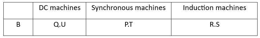


Explanation Locked!
Unlock this branch to view the explanation, track, bookmark and more.
Sign in to UnlockA 3-phase Inductor Motor is driving a constant torque load at rated voltage and frequency. If both voltage and frequency are halved, following statements related to the new condition if stator resistance, leakage reactance and core loss are ignored.
P The difference between synchronous speed and actual speed remains same
Q The air-gap flux remains same
R The stator current remains same
S The p.u. slip remains same
Among the above, correct statements are
Explanation Locked!
Unlock this branch to view the explanation, track, bookmark and more.
Sign in to UnlockA single phase induction motor with only the main winding excited would exhibit the following response at synchronous speed
Explanation Locked!
Unlock this branch to view the explanation, track, bookmark and more.
Sign in to UnlockA single phase transformer has a maximum efficiency of 90% at full load and unity power factor. Efficiency at half load at the same power factor is
Explanation Locked!
Unlock this branch to view the explanation, track, bookmark and more.
Sign in to UnlockFigure shows an ideal single-phase transformer. The primary and secondary coils are wound on the core as shown. Turns ratio . The correct phasors of voltages currents and core flux φ are as shown in


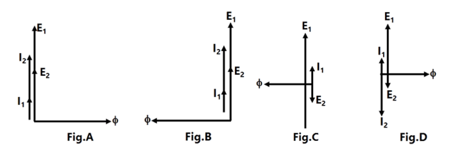
Explanation Locked!
Unlock this branch to view the explanation, track, bookmark and more.
Sign in to UnlockFigure shows a Δ-Y connected 3-phase distribution transformer used to step down the voltage from 11000 V to 415 V line-to line. It has two switches and . Under normal conditions is closed and is open. Under certain special conditions is open and is closed. In such a case the magnitude of the voltage across the LV terminals a and c is


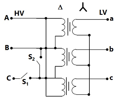
Explanation Locked!
Unlock this branch to view the explanation, track, bookmark and more.
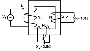
Sign in to UnlockFigure shows an ideal three-winding transformer. The three windings 1, 2, 3 of the transformer are wound on the same core as shown. The turn’s ratio is 4:2:1. A resistor of 10Ω is connected across winding-2. A capacitor of reactance 2.5Ω is connected across winding-3. Widing-1 is connected across a 400 V, ac supply. If the supply voltage phasor = 400∠0°, the supply current phasor is given by


Explanation Locked!
Unlock this branch to view the explanation, track, bookmark and more.
Sign in to UnlockBundled conductors are mainly used in high voltage overhead transmission lines to
Explanation Locked!
Unlock this branch to view the explanation, track, bookmark and more.
Sign in to UnlockChoose two appropriate auxiliary components of a HVDC transmission system from the following
P. D.C. line inductor
Q. A.C. line inductor
R. Reactive power sources
S. Distance relays on D.C. line
T. Series capacitance of A.C. line
Explanation Locked!
Unlock this branch to view the explanation, track, bookmark and more.
Sign in to UnlockA balanced delta connected load of (8+j6) Ω per phase is connected to a 400 V, 50 Hz, 3-phase supply lines. If the input power factor is to be improved to 0.9 by connecting a bank of star connected capacitors the required kVAR of the bank
Explanation Locked!
Unlock this branch to view the explanation, track, bookmark and more.
Sign in to UnlockThe ABCD parameters of a 3-phase overhead transmission line are , and . At no-load condition a shunt inductive reactor is connected at the receiving end of the line to limit the receiving end voltage to be equal to the sending end voltage. The ohmic value of the reactor is


Explanation Locked!
Unlock this branch to view the explanation, track, bookmark and more.
Sign in to UnlockA surge of 20 kV magnitude travels along a lossless cable towards its junction with two identical lossless overhead transmission lines. The inductance and the capacitance of the cable are 0.4mH and 0.5µF per km. The inductance and capacitance of the overhead transmission lines are 1.5mH and 0.015µF per km. The magnitude of the voltage at the junction due to surge is
Explanation Locked!
Unlock this branch to view the explanation, track, bookmark and more.
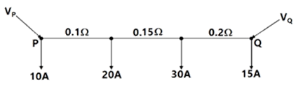
Sign in to UnlockA dc distribution system is shown in Figure with load currents as marked. The two ends of the feeder are fed by voltage sources such that, the value of the voltage for a minimum voltage of 220V at any point along the feeder is


Explanation Locked!
Unlock this branch to view the explanation, track, bookmark and more.
Sign in to UnlockA 3-phase, 11-kV generator feeds power to a constant power unity power factor load of 100 MW through a 3-phase transmission line. The line-to-line voltage at the terminals of the machine is maintained constant at 11 kV. The per unit positive sequence impedance of the line based on 100 MVA and 11 kV is j 0.2. The line-to-line voltage at the load terminals is measured to be less than 11 kV. The total reactive power to be injected at the terminals of the load to increase the line-to-line voltage at the load terminals to 11 kV is
Explanation Locked!
Unlock this branch to view the explanation, track, bookmark and more.
Sign in to Unlock