
A signal where α is a real constant is the input to a Linear Time invariant system whose impulse response where β is a real constant. If min(α,β) denotes the minimum of α and β, and similarly max(α,β) denotes the maximum of α and β, and K is a constant, which one of the following statements is true about the output of the system?


It will be of the form where


It will be of the form where

It will be of the form

It cannot be a sinc type of signal
Explanation Locked!
Unlock this branch to view the explanation, track, bookmark and more.
Sign in to UnlockLet (where rect (x) =1 for and zero otherwise). Then if , the Fourier Transform of will be given by


Explanation Locked!
Unlock this branch to view the explanation, track, bookmark and more.
Sign in to UnlockA function y(t) satisfies the following differential equation: , where δ(t) is the delta function. Assuming zero initial condition and denoting the unit step function by u(t), y(t) can be of the form


Explanation Locked!
Unlock this branch to view the explanation, track, bookmark and more.
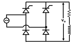
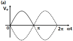
Sign in to UnlockIn the single phase voltage controller circuit shown on the figure, for what range of triggering angle (α), the output voltage is not controllable?

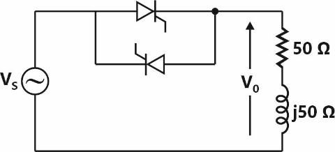


Explanation Locked!
Unlock this branch to view the explanation, track, bookmark and more.
Sign in to UnlockX is a uniformly distributed random variable that takes values between 0 and 1. The value of will be

0


Explanation Locked!
Unlock this branch to view the explanation, track, bookmark and more.
Sign in to UnlockEquation is required to be solved using Newton's method with an initial guess . Then, after one step of Newton’s method, estimate of the solution will be given by


Explanation Locked!
Unlock this branch to view the explanation, track, bookmark and more.
Sign in to UnlockThe number of chords in the graph of the given circuit will be
Explanation Locked!
Unlock this branch to view the explanation, track, bookmark and more.
Sign in to UnlockA signal is the input to a real Linear Time Invariant system. Given K and φ are constants, the output of the system will be of the form where


need not be equal to but equal to


ν need not be equal to but equal to
equal to and equal to
need not be equal and need not be equal to
Explanation Locked!
Unlock this branch to view the explanation, track, bookmark and more.
Sign in to UnlockA differential equation has to be solved using trapezoidal rule of integration with a step size h = 0.01s. Function u(t) indicates a unit step function. If , then value of x at t = 0.01s will be given by:


Explanation Locked!
Unlock this branch to view the explanation, track, bookmark and more.
Sign in to UnlockThe Impulse response of a causal linear time variant system is given as h(t). Now consider the following two statements:
Statement (I): Principle of superposition holds
Statement (II): h(t) = 0 for t < 0.
Which one of the following statements is correct'?
Explanation Locked!
Unlock this branch to view the explanation, track, bookmark and more.
Sign in to UnlockThe transfer functions of two compensators are given below:
,


Which one of the following statements is correct?
is a lead compensator and is a lag compensator


is a lag compensator and , is a lead compensator
Both and are lead compensators
Both and are lag compensators
Explanation Locked!
Unlock this branch to view the explanation, track, bookmark and more.
Sign in to UnlockA lossless power system has to serve a load of 250 MW. There are two generators (and ) in the system with cost curves and respectively defined as follows:


Where and are the MW injections from generator and respectively. Then, the minimum cost dispatch will be


= 250 MW; = 0 MW
= 150 MW; = 100 MW
= 100 MW; = 150 MW
= 100 MW; = 250 MW
Explanation Locked!
Unlock this branch to view the explanation, track, bookmark and more.
Sign in to UnlockA 220 V, 20 A, 1000 rpm, separately excited dc motor has an armature resistance of 2.5Ω. The motor is controlled by a step down chopper with a frequency of 1 kHz. The input dc voltage to the chopper is 250 V. The duty cycle of the chopper for the motor to operate at a speed of 600 rpm delivering the rated torque will be
Explanation Locked!
Unlock this branch to view the explanation, track, bookmark and more.
Sign in to UnlockA system with input x(t) and output y(t) is defined by the input-output relation:

The system will be
Explanation Locked!
Unlock this branch to view the explanation, track, bookmark and more.
Sign in to UnlockConsider function where x is a real number. Then the function has

Explanation Locked!
Unlock this branch to view the explanation, track, bookmark and more.
Sign in to UnlockH(z) is a transfer function of a real system. When a signal is the input to such a system, the output is zero. Further the Region of Convergence (ROC) of is the entire Z-plane (except z = 0). It can then be inferred that H(z) can have a minimum of


Explanation Locked!
Unlock this branch to view the explanation, track, bookmark and more.
Sign in to UnlockThe AC bridge shown in the figure is used to measure the impedance Z.
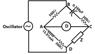
If the bridge is balanced for oscillator frequency f =2 kHz, then the impedance Z will be


Explanation Locked!
Unlock this branch to view the explanation, track, bookmark and more.
Sign in to UnlockThe asymptotic Bode magnitude plot of a minimum phase transfer function is shown in the figure:
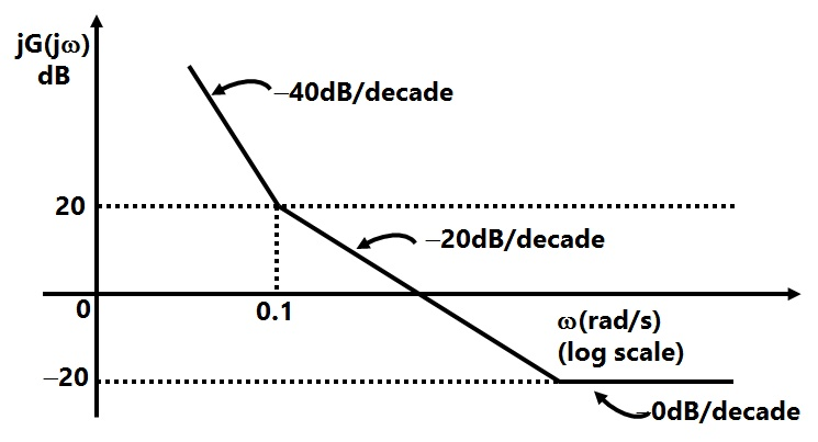
This transfer function has
Explanation Locked!
Unlock this branch to view the explanation, track, bookmark and more.
Sign in to UnlockGiven with , the residue of at for will be


Explanation Locked!
Unlock this branch to view the explanation, track, bookmark and more.
Sign in to UnlockLet x(t) be a periodic signal with time period T, Let for some . The Fourier Series coefficients of y(t) are denoted by . If for all odd k, then can be equal to


2T
Explanation Locked!
Unlock this branch to view the explanation, track, bookmark and more.
Sign in to UnlockA 220V, 1400 rpm, 40A separately excited dc motor has an armature resistance of 0.4Ω. The motor is fed from a single phase circulating current dual converter with an input ac line voltage of 220V (RMS). The approximate firing angles of the dual converter for motoring operation at 50% of rated torque and 1000 rpm will be
Explanation Locked!
Unlock this branch to view the explanation, track, bookmark and more.
Sign in to UnlockIn a stepper motor, the detent torque means
Explanation Locked!
Unlock this branch to view the explanation, track, bookmark and more.
Sign in to UnlockGiven a sequence x(n], to generate the sequence, which one of the following procedures would be correct?

First delay x[n] by 3 samples to generate , then pick every samples of to generate , and then finally time reverse to obtain y[n].


First advance x[n] by 3 samples to generate , then pick every samples of to generate , and then finally time reverse to obtain y[n]
First pick every fourth sample of x[n] to generate , time reverse to obtain , and finally advance by 3 samples to obtain y[n]


First pick every fourth sample of x[n] to generate , time reverse to obtain , and finally delay by 3 samples to obtain y[n]
Explanation Locked!
Unlock this branch to view the explanation, track, bookmark and more.
Sign in to UnlockA 3 line to 8 line decoder, with active low outputs, is used to implement a 3-variable Boolean function as shown in the figure.
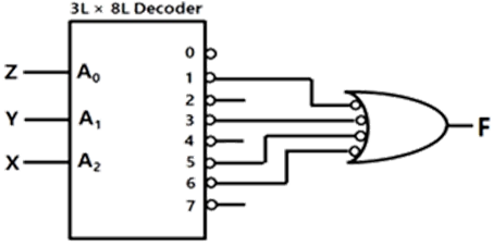
The simplified form of Boolean function F(A, B, C) Implemented in 'Product of Sum' form will be


Explanation Locked!
Unlock this branch to view the explanation, track, bookmark and more.
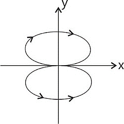
Sign in to UnlockTwo sinusoidal signals and are applied to X and Y inputs of a dual channel CRO. The Lissajous figure displayed on the screen is shown below:


The signal will be expressed as


Explanation Locked!
Unlock this branch to view the explanation, track, bookmark and more.
Sign in to UnlockThe equivalent circuits of a diode, during forward biased and reverse biased conditions, are shown in the figure.


If such a diode is used in clipper circuit of figure given above, the output voltage of the circuit will be

Explanation Locked!
Unlock this branch to view the explanation, track, bookmark and more.
Sign in to UnlockThe truth table of a monoshot shown in the figure is given in the table below:
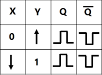
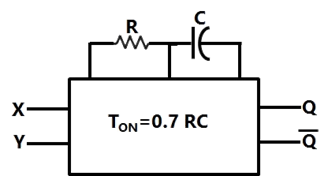
Two monoshots, one positive edge triggered and other negative edge triggered, are connected as shown in the figure. The pulse widths of the two monoshot outputs, , and , are and , respectively.


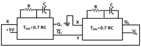
The frequency and the duty cycle of the signal at Q1 will respectively be


Explanation Locked!
Unlock this branch to view the explanation, track, bookmark and more.
Sign in to UnlockA 3-phase Voltage Source Inverter is operated in 180° conduction mode. Which one of the following statements is true?
Both pole-voltage and line-voltage will have harmonic components

Pole-voltage will have 3rd harmonic component but line-voltage will be free from 3rd harmonic
Line-voltage will have 3rd harmonic component but pole-voltage will be free from 3rd harmonic
Both pole-voltage and lone-voltage will be free from 3rd harmonic components
Explanation Locked!
Unlock this branch to view the explanation, track, bookmark and more.
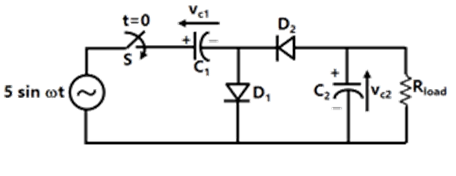
Sign in to UnlockIn the voltage doubler circuit shown in the figure, the switch 'S' is closed at t=0. Assuming diodes , and , to be ideal, load resistance to be infinite and initial capacitor voltages to be zero, the steady state voltage across capacitors , and , will be


Explanation Locked!
Unlock this branch to view the explanation, track, bookmark and more.
Sign in to UnlockA single phase voltage source inverter is feeding a purely inductive load as shown in the figure.

The inverter is operated at 50Hz in 180° square wave mode. Assume that the load current does not have any dc component. The peak value of the inductor current will be

Explanation Locked!
Unlock this branch to view the explanation, track, bookmark and more.
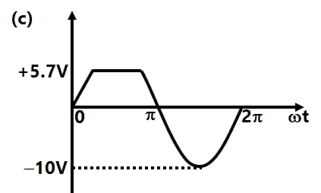
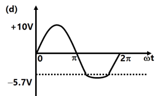
Sign in to UnlockThe block diagrams of two types of half wave rectifiers are shown in the figure. The transfer characteristics of the rectifiers are also shown within the block.
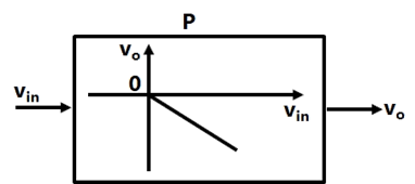
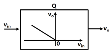
It is desired to make full wave rectifier using above two half-wave rectifiers. The resultant circuit will be
Explanation Locked!
Unlock this branch to view the explanation, track, bookmark and more.
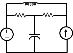
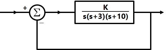
Sign in to UnlockFigure shows a feedback system where K>0.
The range of K for which the system is stable will be given by


Explanation Locked!
Unlock this branch to view the explanation, track, bookmark and more.
Sign in to UnlockTwo 8-bit ADCs, one of single slope integrating type and other of successive approximation type, take and times to convert 5V analog input signal to equivalent digital output. If the input analog signal is reduced to 2.5V, the approximate lime taken by the two ADCs will respectively be


Explanation Locked!
Unlock this branch to view the explanation, track, bookmark and more.
Sign in to UnlockThe state space equation of a system is described by


Where x is state vector, u is input, y is output and

The transfer function G(s) of this system will be


Explanation Locked!
Unlock this branch to view the explanation, track, bookmark and more.
Sign in to UnlockThe state space equation of a system is described by
Where x is state vector, u is input, y is output and
A unity feedback is provided to the above system G(s) to make it a closed loop system as shown in figure.
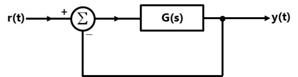
For a unit step input r(t), the steady state error In the output will be
0
1
2

Explanation Locked!
Unlock this branch to view the explanation, track, bookmark and more.
Sign in to UnlockIn the circuit shown in the figure, the switch is operated at a duty cycle of 0.5. A large capacitor is connected across the load. The inductor current is assumed to be continuous. The average voltage across the load and the average current through the diode will respectively be

Explanation Locked!
Unlock this branch to view the explanation, track, bookmark and more.
Sign in to UnlockA coil of 300 turns is wound on a non-magnetic core having a mean circumference of 300 mm and a cross-sectional area of . The inductance of the coil corresponding to a magnetizing current of 3A will be
(Given that)

Explanation Locked!
Unlock this branch to view the explanation, track, bookmark and more.
Sign in to UnlockAn input device is interfaced with Intel 8085A microprocessor as memory mapped I/O. The address of the device is 2500H. In order to input data from the device to accumulator, the sequence of instructions will be
Explanation Locked!
Unlock this branch to view the explanation, track, bookmark and more.
Sign in to UnlockThe characteristic equation of a (3 × 3) matrix P is defined as. If I denote identity matrix, then the inverse of matrix P will be


Explanation Locked!
Unlock this branch to view the explanation, track, bookmark and more.
Sign in to UnlockThe contents (in Hexadecimal) or some of the memory locations in an 8085A based system are given below:
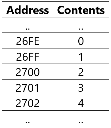
The contents of stack pointer (SP), program counter (PC) and (HL) are 2700H, 2100H and 0000H respectively. When the following sequence of instructions are executed,
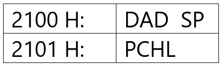
The contents of (SP) and (PC) at the end of execution will be
Explanation Locked!
Unlock this branch to view the explanation, track, bookmark and more.
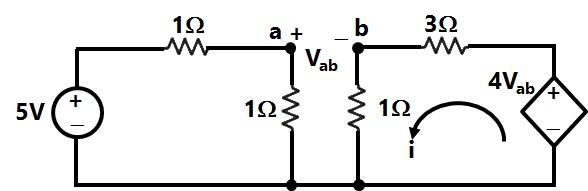
Sign in to UnlockAssuming ideal elements in the circuit shown below, the voltage will be

Explanation Locked!
Unlock this branch to view the explanation, track, bookmark and more.
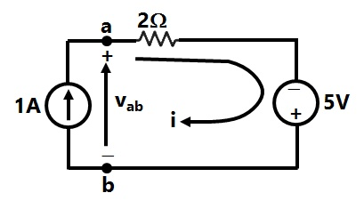
Sign in to UnlockIn the circuit shown in the figure. The value of the current i will be given by
Explanation Locked!
Unlock this branch to view the explanation, track, bookmark and more.
Sign in to UnlockTwo perfectly matched silicon transistors are connected as shown in the figure. Assuming the β of the transistors to be very high and the forward voltage drop in diodes to be 0.7V, the value of current I is
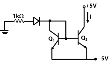
Explanation Locked!
Unlock this branch to view the explanation, track, bookmark and more.
Sign in to UnlockIf the rank of a (5×6) matrix Q is 4, then which one of the following statements is correct?
Q will have four linearly independent rows and four linearly Independent columns
Q will have four linearly Independent rows and five linearly Independent columns
will be invertible

will be invertible

Explanation Locked!
Unlock this branch to view the explanation, track, bookmark and more.
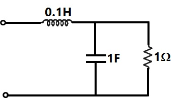
Sign in to UnlockThe time constant for the given circuit will be
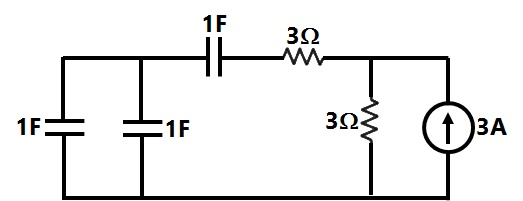


4s
9s
Explanation Locked!
Unlock this branch to view the explanation, track, bookmark and more.
Sign in to UnlockThe current i(t) sketched in the figure flows through an initially uncharged 0.3nF capacitor.
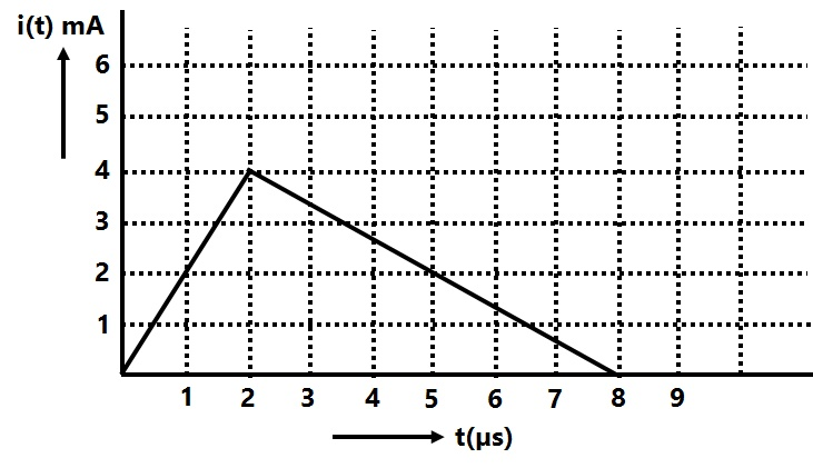
The charge stored in the capacitor at t = 5µs, will be
Explanation Locked!
Unlock this branch to view the explanation, track, bookmark and more.
Sign in to UnlockA two machine power system is shown below. Transmission line XY has positive sequence Impedance of and zero sequence impedance of .


An 'a' phase to ground fault with zero fault impedance occurs at the center of the transmission line. Bus voltage at X and line current from X to F for the phase 'a', are given by Volts and Amperes, respectively. Then, the impedance measured by the ground distance relay located at the terminal X of line XY will be given by


Explanation Locked!
Unlock this branch to view the explanation, track, bookmark and more.
Sign in to UnlockA is a m×n full ran matrix with m > n and I is an identity matrix. Let matrix. Then, which one of the following statements is FALSE?


Explanation Locked!
Unlock this branch to view the explanation, track, bookmark and more.
Sign in to UnlockA capacitor consists of two metal plates each and spaced 6 mm apart. The space between the metal plates is filled with a glass plate of 4 mm thickness and a layer of paper of 2 mm thickness. The relative permittivity of the glass and paper are 8 and 2 respectively. Neglecting the fringing effect, the capacitance will be

(Given that )

Explanation Locked!
Unlock this branch to view the explanation, track, bookmark and more.
Sign in to UnlockThe current i(t) sketched in the figure flows through an initially uncharged 0.3nF capacitor.
The capacitor charged up to 5µs, as per the current profile given in the figure, is connected across an
inductor of 0.6mH. Then the value of voltage across the capacitor after 1µs will approximately be
Explanation Locked!
Unlock this branch to view the explanation, track, bookmark and more.
Sign in to UnlockLet P be a 2 ´ 2 real orthogonal matrix and is a real vector with length. Then, which one of the following statements is correct?


where at least one vector satisfies
for all vectors

where at least one vector satisfies
No relationship can be established between and


Explanation Locked!
Unlock this branch to view the explanation, track, bookmark and more.
Sign in to UnlockTwo point charges and are placed at coordinates (1, 1, 0) and (−1, −1, 0) respectively. The total electric flux passing through a plane z = 20 will be


Explanation Locked!
Unlock this branch to view the explanation, track, bookmark and more.
Sign in to UnlockVoltage phasors at the two terminals of a transmission line of length 70 km have a magnitude of 1.0 per unit but are 180 degrees out of phase. Assuming that the maximum load current in the line is 1/5th of minimum 3-phase fault current, which one of the following transmission line protection schemes will NOT pick up for this condition?
Explanation Locked!
Unlock this branch to view the explanation, track, bookmark and more.
Sign in to UnlockA lossless single machine infinite bus power system is shown below:
The synchronous generator transfers 1.0 per unit of power to the infinite bus. The critical clearing time of circuit breaker is 0.28s. If another identical synchronous generator is connected in parallel to the existing generator and each generator is scheduled to supply 0.5 per unit of power, then the critical clearing time of the circuit breaker will

Explanation Locked!
Unlock this branch to view the explanation, track, bookmark and more.
Sign in to UnlockThe transfer function of a linear time invariant system is given as

The steady state value of the output of this system for a unit impulse input applied at time instant t = 1 will be
Explanation Locked!
Unlock this branch to view the explanation, track, bookmark and more.
Sign in to UnlockThe transfer function of a system is given as

This system is
Explanation Locked!
Unlock this branch to view the explanation, track, bookmark and more.
Sign in to UnlockA 3-phase transmission line is shown in the figure:

Voltage drop across the transmission line is given by the following equation:

Shunt capacitance of the line can be neglected. If the line has positive sequence impedance of 15Ω and zero sequence impedance of 48Ω, then the values of , and will be


Explanation Locked!
Unlock this branch to view the explanation, track, bookmark and more.
Sign in to UnlockConsider a power system shown below:

Given that:

The positive sequence impedances are
and


3-phase Base MVA = 100
Voltage base = 400 kV (Line to Line)
Nominal system frequency = 50 Hz
The reference voltage for phase ‘a’ is defined as

A symmetrical three phase fault occurs at centre of the line. i.e. point 'F’ at time . The positive sequence impedance from source to point 'F' equals 0.004+ j0.04pu. The waveform correspond phase 'a' fault current from bus X reveals that decaying dc offset current is negative and in magnitude at its maximum initial value. Assume that the negative sequence impedances are equal to positive sequence impedances, and the zero sequence impedances are three times positive sequence impedances.


The instantof the fault will be

Explanation Locked!
Unlock this branch to view the explanation, track, bookmark and more.
Sign in to UnlockConsider a power system shown below:
Given that:
The positive sequence impedances are and
3-phase Base MVA = 100
Voltage base = 400 kV (Line to Line)
Nominal system frequency = 50 Hz
The reference voltage for phase ‘a’ is defined as
A symmetrical three phase fault occurs at centre of the line. i.e. point 'F’ at time . The positive sequence impedance from source to point 'F' equals 0.004+ j0.04pu. The waveform correspond phase 'a' fault current from bus X reveals that decaying dc offset current is negative and in magnitude at its maximum initial value. Assume that the negative sequence impedances are equal to positive sequence impedances, and the zero sequence impedances are three times positive sequence impedances.
The RMS value of the ac component of fault currentwill be

Explanation Locked!
Unlock this branch to view the explanation, track, bookmark and more.
Sign in to UnlockConsider a power system shown below:
Given that:
The positive sequence impedances are and
3-phase Base MVA = 100
Voltage base = 400 kV (Line to Line)
Nominal system frequency = 50 Hz
The reference voltage for phase ‘a’ is defined as
A symmetrical three phase fault occurs at centre of the line. i.e. point 'F’ at time . The positive sequence impedance from source to point 'F' equals 0.004+ j0.04pu. The waveform correspond phase 'a' fault current from bus X reveals that decaying dc offset current is negative and in magnitude at its maximum initial value. Assume that the negative sequence impedances are equal to positive sequence impedances, and the zero sequence impedances are three times positive sequence impedances.
Instead of the three phase fault, if a single line to ground fault occurs on phase 'a' at Point 'F' with zero fault impedance, then the RMS value of the ac component of fault current for phase 'a’ will be
Explanation Locked!
Unlock this branch to view the explanation, track, bookmark and more.
Sign in to UnlockA single phase fully controlled bridge converter supplies a load drawing constant and ripple free load current. If the triggering angle is 30°, the input power factor will be
Explanation Locked!
Unlock this branch to view the explanation, track, bookmark and more.
Sign in to UnlockA single-phase half controlled converter shown in the figure is feeding power to highly inductive load. The converter is operating at a firing angle of 60°.
If the firing pulses are suddenly removed, the steady state voltage waveform of the converter will become

Explanation Locked!
Unlock this branch to view the explanation, track, bookmark and more.
Sign in to UnlockThe Thevenin's equivalent of a circuit operating at, has and . At this frequency, the minimal realization of the Thevenin's impedance will have a


Explanation Locked!
Unlock this branch to view the explanation, track, bookmark and more.
Sign in to UnlockA single phase fully controlled converter bridge is used for electrical braking of a separately excited dc motor. The dc motor load is represented by an equivalent circuit as shown in the figure. Assume that the load inductance is sufficient to ensure continuous and ripple free load current. The firing angle of the bridge for a load current will be


Explanation Locked!
Unlock this branch to view the explanation, track, bookmark and more.
Sign in to UnlockThe resonant frequency for the given circuit will be
Explanation Locked!
Unlock this branch to view the explanation, track, bookmark and more.
Sign in to UnlockA three phase fully controlled bridge converter is feeding a load drawing a constant and ripple free load current of 10A at a firing angle of 30°. The approximate Total Harmonic Distortion (%THD) and the RMS value of fundamental component of the input current will respectively be
Explanation Locked!
Unlock this branch to view the explanation, track, bookmark and more.
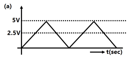
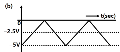
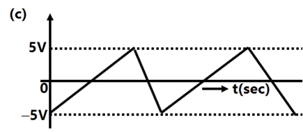
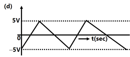
Sign in to UnlockA waveform generator circuit using OPAMPs is shown in the figure. It produces a triangular wave at point ‘P’ with a peak to peak voltage of 5 V for.

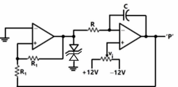
If voltage is made +2.5V, the voltage waveform at point ‘P’ will become

Explanation Locked!
Unlock this branch to view the explanation, track, bookmark and more.
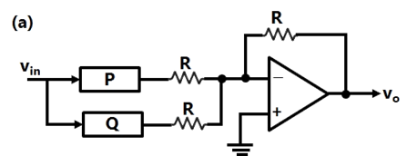
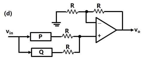
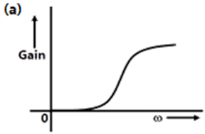
Sign in to UnlockA general filter circuit is shown in the figure:
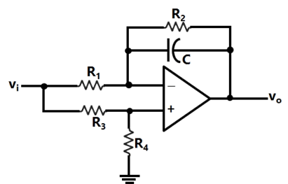
If and , the circuit acts as a


Explanation Locked!
Unlock this branch to view the explanation, track, bookmark and more.
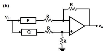
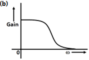
Sign in to UnlockA general filter circuit is shown in the figure:
The output of the filter is given to the circuit shown in figure:
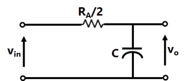
The gain vs frequency characteristic of the output will be

Explanation Locked!
Unlock this branch to view the explanation, track, bookmark and more.
Sign in to UnlockA 240V, dc shunt motor draws 15A while supplying the rated load at a speed of 80 rad/s. The armature resistance is 0.5Ω and the field winding resistance is 80Ω.
The net voltage across the armature resistance at the time of plugging will be
Explanation Locked!
Unlock this branch to view the explanation, track, bookmark and more.
Sign in to UnlockA 240V, dc shunt motor draws 15A while supplying the rated load at a speed of 80 rad/s. The armature resistance is 0.5Ω and the field winding resistance is 80Ω.
The external resistance to be added in the armature circuit to limit the armature current to 125% of its rated value is
Explanation Locked!
Unlock this branch to view the explanation, track, bookmark and more.
Sign in to UnlockDistributed winding and short chording employed in AC machines will result in
Explanation Locked!
Unlock this branch to view the explanation, track, bookmark and more.
Sign in to UnlockA synchronous motor is connected to an infinite bus at 1.0pu voltage and draws 0.6pu current at unity power factor. Its synchronous reactance is 1.0pu and resistance is negligible.
The excitation voltage (E) and load angle (δ) will respectively be
Explanation Locked!
Unlock this branch to view the explanation, track, bookmark and more.
Sign in to UnlockA synchronous motor is connected to an infinite bus at 1.0pu voltage and draws 0.6pu current at unity power factor. Its synchronous reactance is 1.0pu and resistance is negligible.
Keeping the excitation voltage same, the load on the motor is increased such that the motor current increases by 20%. The operating power factor will become
Explanation Locked!
Unlock this branch to view the explanation, track, bookmark and more.
Sign in to UnlockThree single-phase transformers are connected to form a 3-phase transformer bank. The transformers are connected in the following manner:
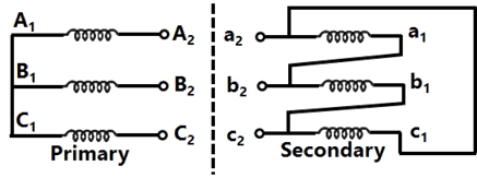
The transformer connection will be represented by
Explanation Locked!
Unlock this branch to view the explanation, track, bookmark and more.
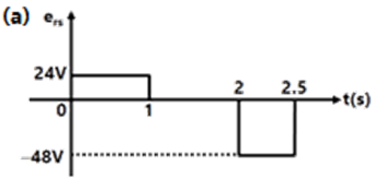
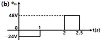
Sign in to UnlockThe core of a two-winding transformer is subjected to a magnetic flux variation as indicated in the figure.
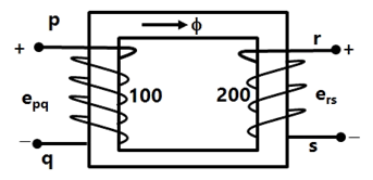
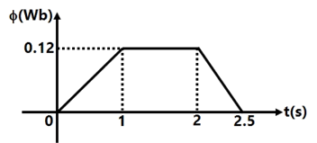
The induced emf in the secondary winding as a function of time will be of the form


Explanation Locked!
Unlock this branch to view the explanation, track, bookmark and more.
Sign in to UnlockIt is desired to measure parameters of 230V / 115V, 2kVA, single-phase transformer. The following watt-meters are available in a laboratory:
: 250V, 10A. Low Power Factor

: 250V, 5A. Low Power Factor

: 150V, 10A. High Power Factor

: 150V, 5A. High Power Factor

The watt-meters used in open circuit test and short circuit test of the transformer will respectively be


Explanation Locked!
Unlock this branch to view the explanation, track, bookmark and more.
Sign in to UnlockA 230V. 50 Hz, 4-pole, single-phase induction motor is rotating in the clockwise (forward) direction at a speed of 1425 rpm. If the rotor resistance at standstill is 7.8Ω, then the effective rotor resistance in the backward branch of the equivalent circuit will be
Explanation Locked!
Unlock this branch to view the explanation, track, bookmark and more.
Sign in to UnlockA 400 V, 50 Hz, 30 hp, three-phase induction motor is drawing 50 A current at 0.8 power factor lagging. The stator and rotor copper losses are 1.5 kW and 900 W respectively. The friction and windage losses are 1050W and the core losses are 1200 W. The air-gap power of the motor will be
Explanation Locked!
Unlock this branch to view the explanation, track, bookmark and more.
Sign in to UnlockA 400 V, 50 Hz, 4 pole, 1400 rpm, Star connected squirrel cage induction motor has the following parameters referred to the stator:

Neglect stator resistance and core and rotational losses of the motor.
The motor is controlled from a 3-phase voltage Source inverter with constant V/f control. The stator line-to-line voltage (RMS) and frequency to obtain the maximum torque at starting will be:
Explanation Locked!
Unlock this branch to view the explanation, track, bookmark and more.
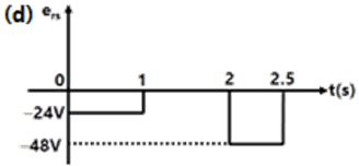
Sign in to UnlockA 3-phase, 440 V, 50 Hz, 4-pole, slip ring induction motor is fed from the rotor side through an autotransformer and the stator is connected to a variable resistance as shown in the figure.
The motor is coupled to a 220V, separately excited, dc generator feeding power to fixed resistance of10Ω. Two-wattmeter method is used to measure the input power to induction motor. The variable resistance is adjusted such that the motor runs at 1410 rpm and the following readings were recorded:
,


The speed of rotation of stator magnetic field with respect to rotor structure will be
Explanation Locked!
Unlock this branch to view the explanation, track, bookmark and more.
Sign in to UnlockA 3-phase, 440 V, 50 Hz, 4-pole, slip ring induction motor is fed from the rotor side through an autotransformer and the stator is connected to a variable resistance as shown in the figure.
The motor is coupled to a 220V, separately excited, dc generator feeding power to fixed resistance of10Ω. Two-wattmeter method is used to measure the input power to induction motor. The variable resistance is adjusted such that the motor runs at 1410 rpm and the following readings were recorded:
,
Neglecting all losses of both the machines, the dc generator power output and the current through resistance will respectively be

Explanation Locked!
Unlock this branch to view the explanation, track, bookmark and more.
Sign in to UnlockAn extra high voltage transmission line of length 300 km can be approximated by a lossless line having propagation constant β=0.00127 radians per km. Then the percentage ratio of line length to wavelength will be given by
Explanation Locked!
Unlock this branch to view the explanation, track, bookmark and more.
Sign in to UnlockA lossless transmission line having Surge Impedance Loading (SIL) of 2280 MW is provided with a uniformly distributed series capacitive compensation of 30%. Then, SIL of the compensated transmission line will be
Explanation Locked!
Unlock this branch to view the explanation, track, bookmark and more.
Sign in to UnlockSingle line diagram of a 4-bus single source distribution system is shown below. Branches and have equal impedances. The load current values indicated in the figure are in per unit.


Distribution Company’s policy requires radial system operation with minimum loss, this can be achieved by opening of the branch


Explanation Locked!
Unlock this branch to view the explanation, track, bookmark and more.
Sign in to Unlock