Analog Electronics
Amplifiers
Practice questions from Amplifiers.
11
Total0
Attempted0
Correct0
IncorrectA current controlled current source (CCCS) has an input impedance of and output impedance of . When this CCCS is used in a negative feedback closed loop with a loop gain of 9, the closed loop output impedance is


Explanation Locked!
Unlock this branch to view the explanation, track, bookmark and more.
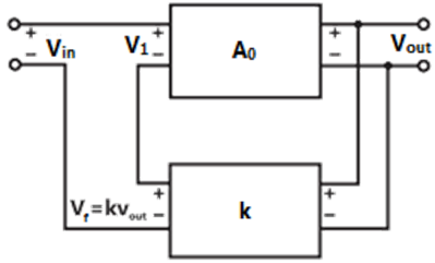
Sign in to UnlockIn the feedback network shown below, if the feedback factor k is increased, then the
Explanation Locked!
Unlock this branch to view the explanation, track, bookmark and more.
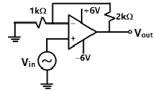
Sign in to UnlockThe nature of feedback in the op-amp circuit shown is
Explanation Locked!
Unlock this branch to view the explanation, track, bookmark and more.
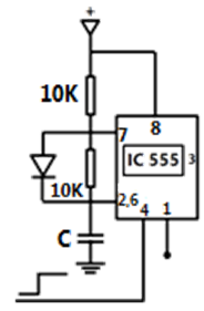
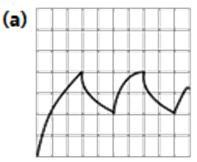
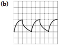
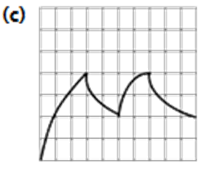
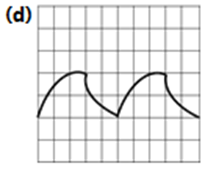
Sign in to UnlockIC 555 in the adjacent figure is configured as an Astable multi-vibrator. It is enabled to oscillate at t=0 by applying a high input to pin 4. The pin description is: 1 and 8 − supply: 2-trigger; 4-reset; 6-threshold; 7-discharge. The waveform appearing across the capacitor starting from t=0, as observed on a storage CRO is
Explanation Locked!
Unlock this branch to view the explanation, track, bookmark and more.
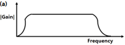
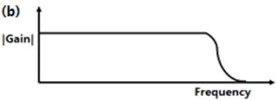
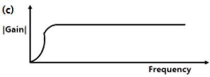
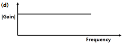
Sign in to UnlockThe typical frequency response of a two-stage direct coupled voltage amplifier is as shown in
Explanation Locked!
Unlock this branch to view the explanation, track, bookmark and more.
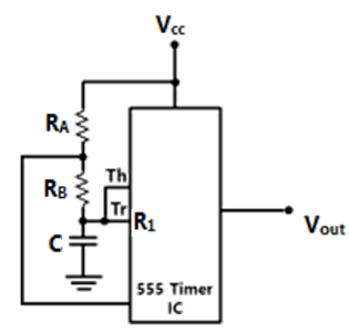
Sign in to UnlockThe circuit of Figure shows a 555 Timer IC connected as an Astable multi-vibrator. The value of the capacitor C is 10nF. The values of the resistors and for a frequency of 10kHz and a duty cycle of 0.75 for the output voltage waveform are


Explanation Locked!
Unlock this branch to view the explanation, track, bookmark and more.
Sign in to UnlockThe type of power amplifier which exhibits crossover distortion in its output is
Explanation Locked!
Unlock this branch to view the explanation, track, bookmark and more.
Sign in to UnlockA current amplifier has an input resistance of 10Ω, an output resistance of 10kΩ and a current gain of 1000. It is feed by a current source having a source resistance of 10k Ω and its output is connected to a 10 Ω load resistance.
Explanation Locked!
Unlock this branch to view the explanation, track, bookmark and more.
Sign in to UnlockThe voltage series feedback in a feedback amplifier leads to
Explanation Locked!
Unlock this branch to view the explanation, track, bookmark and more.
Sign in to UnlockA practical R-C sinusoidal oscillator is built using a positive feedback amplifier with a closed loop-gain slightly less than unity. (True=1, False=0)
Explanation Locked!
Unlock this branch to view the explanation, track, bookmark and more.
Sign in to UnlockA Wien bridge oscillator is shown in figure. Which of the following statements are true, if f is the frequency of oscillation.
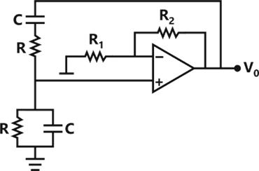
For


For


The gain of the op amp stage should be less than two for proper operation
The gain of the op amp stage should be three for proper operation
Explanation Locked!
Unlock this branch to view the explanation, track, bookmark and more.
Sign in to Unlock