Measurement
CRO
Practice questions from CRO.
19
Total0
Attempted0
Correct0
IncorrectThe slope and level detector circuit in a CRO has a delay of 100 ns. The start-stop sweep generator has a response time of 50 ns. In order to display correctly, a delay line of
Sign in to see the solution
Log in to view the explanation, track your attempts, and keep your progress.
Sign in to UnlockA stationary closed Lissajous pattern on an oscilloscope has 3 horizontal tangencies and 2 vertical tangencies for a horizontal input with frequency 3 kHz. The frequency of the vertical input is
Sign in to see the solution
Log in to view the explanation, track your attempts, and keep your progress.
Sign in to UnlockIn an oscilloscope screen, linear sweep is applied at the
Sign in to see the solution
Log in to view the explanation, track your attempts, and keep your progress.
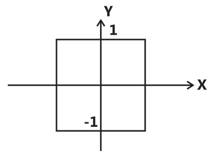
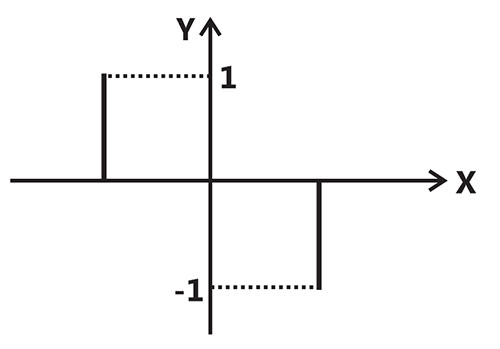
Sign in to UnlockThe two signals S1 and S2, shown in figure, are applied to Y and X deflection plates of an oscilloscope.
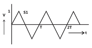
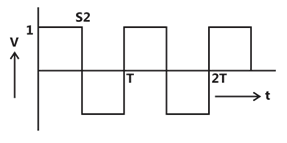
The waveform displayed on the screen is
Sign in to see the solution
Log in to view the explanation, track your attempts, and keep your progress.
Sign in to UnlockA dual trace oscilloscope is set to operate in the alternate mode. The control input of the multiplexer used in the y-circuit is fed with a signal having a frequency equal to
Sign in to see the solution
Log in to view the explanation, track your attempts, and keep your progress.
Sign in to UnlockThe two inputs of a CRO are fed with two stationary periodic signals. In the X-Y mode, the screen shows a figure which changes from ellipse to circle and back to ellipse with its major axis changing orientation slowly and repeatedly. The following inference can be made from this.
Sign in to see the solution
Log in to view the explanation, track your attempts, and keep your progress.
Sign in to UnlockTwo sinusoidal signals and are applied to X and Y inputs of a dual channel CRO. The Lissajous figure displayed on the screen is shown below:


The signal will be expressed as


Sign in to see the solution
Log in to view the explanation, track your attempts, and keep your progress.
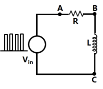
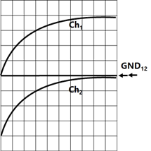
Sign in to UnlockThe probes of a non-isolated, two-channel oscilloscope are clipped to points A. B and C in the circuit of the adjacent figure Vin is a square wave of a suitable low frequency. The display on Ch1 and Ch2 are as shown on the right. Then the “Signal” and “Ground” probes S1, G1 and S2, G2 of Ch1 and Ch2 respectively are connected to points
Sign in to see the solution
Log in to view the explanation, track your attempts, and keep your progress.
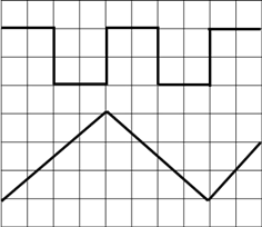
Sign in to UnlockThe time/div and voltage/div axes of an oscilloscope have been erased. A student connects a 1 kHz, 5V p-p square wave calibration pulse to channel 1 of the scope and observes the screen to be as shown in the upper trace of the figure. An unknown signal is connected to channel 2 (lower trace) of the scope. If the time/div and V/div on both channels are the same, the amplitude (p-p) and period of the unknown signal are respectively
Sign in to see the solution
Log in to view the explanation, track your attempts, and keep your progress.
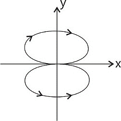
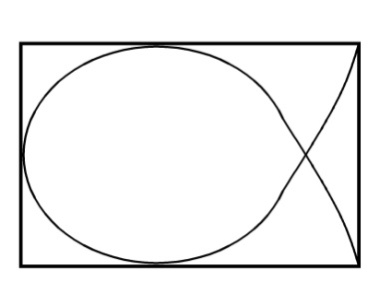
Sign in to UnlockThe simultaneous application of signals x(t) and y (t) to the horizontal and vertical plates, respectively, of an oscilloscope, produces a vertical figure-of - 8 display. If P and Q are constants, and x(t)=P sin(4t+30) , then y (t) is equal to
Sign in to see the solution
Log in to view the explanation, track your attempts, and keep your progress.
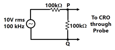
Sign in to UnlockA CRO probe has an impedance of 500 kΩ in parallel with a capacitance of 10pF. The probe is used to measure the voltage between P and Q as shown in figure. The measured voltage will be
Sign in to see the solution
Log in to view the explanation, track your attempts, and keep your progress.
Sign in to UnlockGroup II represents the figures obtained on a CRO screen when the voltage signals and are given to its X and Y plates respectively and Φ is changed. Choose the correct value of Φ from Group I to match with the corresponding figure of Group II


Group I
P. Φ = 0 Q. Φ =

R. S.


Group II


Sign in to see the solution
Log in to view the explanation, track your attempts, and keep your progress.
Sign in to UnlockTwo in-phase 50 Hz sinusoidal waveform of unit amplitude are fed into channel 1 and channel 2 respectively of an oscilloscope. Assuming that the voltage scale, time scale and other settings are exactly the same for both the channels, what would be observed if the oscilloscope is operated in X-Y mode?
Sign in to see the solution
Log in to view the explanation, track your attempts, and keep your progress.
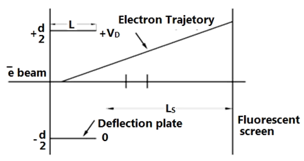
Sign in to UnlockFig shows the electrostatic vertical deflection system of CRT. Given that is the accelerating voltage, the deflection sensitivity (deflection/volt) is proportional to:


Sign in to see the solution
Log in to view the explanation, track your attempts, and keep your progress.
Sign in to UnlockIn an oscilloscope, the input to the horizontal plates is a 100 Hz voltage signal. The Lissajous patterns (A), (B) and (C) will be generated when different frequency voltage signals are applied to vertical plates. Match each Lissajous pattern to the corresponding frequency .

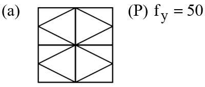
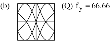
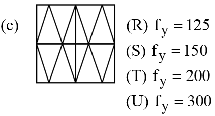
Sign in to see the solution
Log in to view the explanation, track your attempts, and keep your progress.
Sign in to UnlockA certain oscilloscope with 4 cm by 4 cm screen has its own sweep output fed to its input. If the x and y sensitivities are same, the oscilloscope will display a
Sign in to see the solution
Log in to view the explanation, track your attempts, and keep your progress.
Sign in to UnlockAn oscilloscope is operated in the X-Y mode. The figure 8 is displayed on the oscilloscope screen. If the frequency of the X-input is 1 kHz, the Y-input frequency is _____________________.
Sign in to see the solution
Log in to view the explanation, track your attempts, and keep your progress.
Sign in to UnlockA Lissajous pattern, as shown in figure, is observed on the screen of a CRO when voltages of frequencies are applied to the x and y plates respectively. is then equal to


Sign in to see the solution
Log in to view the explanation, track your attempts, and keep your progress.
Sign in to UnlockA CRO screen has ten divisions on the horizontal scale. If a voltage signal is examined with a line base setting of 5msec/div, the number of cycles of signal displayed on the screen will be

Sign in to see the solution
Log in to view the explanation, track your attempts, and keep your progress.
Sign in to Unlock