Electrical Machines
Transformers
Practice questions from Transformers.
112
Total0
Attempted0
Correct0
IncorrectA , single-phase two-winding transformer is configured as a autotransformer.


What will be the rating of the autotransformer?
Sign in to see the solution
Log in to view the explanation, track your attempts, and keep your progress.
Sign in to UnlockA single-phase transformer is designed for use in India and rated 100 VA at 50 Hz . Later, this unit is shipped to the USA where it is used as a transformer at 60 Hz .


Which of the following statements is/are correct?
Sign in to see the solution
Log in to view the explanation, track your attempts, and keep your progress.
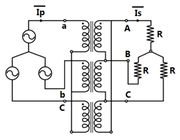
Sign in to UnlockThree single-phase transformers are connected to form a three-phase transformer bank with connections as shown.

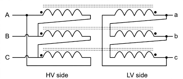
Considering phase sequence, the vector group of the transformer is:

Sign in to see the solution
Log in to view the explanation, track your attempts, and keep your progress.
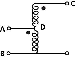
Sign in to UnlockThe transformer connection given in the figure is part of a balanced 3-phase circuit where the phase sequence is "". The primary to secondary turns ratio is . If , then the relationship between and will be


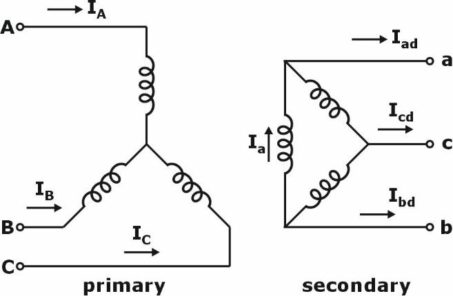
and lags by .


and leads by .
and lags by .

and leads by .
Sign in to see the solution
Log in to view the explanation, track your attempts, and keep your progress.
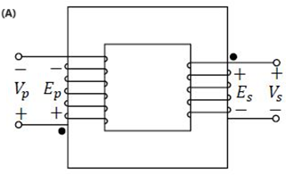
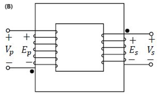
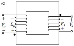
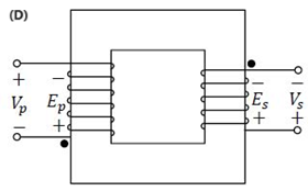
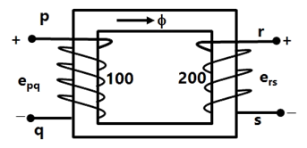
Sign in to UnlockWhich one of the following options represents possible voltage polarities in a single phase two winding transformer? Here, is the applied primary voltage, is the induced primary voltage, is the open circuit secondary voltage, and is the induced secondary voltage.


Sign in to see the solution
Log in to view the explanation, track your attempts, and keep your progress.
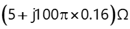
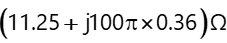
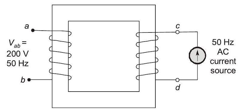
Sign in to UnlockWhen the winding of the single-phase, , two winding transformer is supplied from an AC current source of frequency , the rated voltage of (rms), is obtained at the open-circuited terminals . The cross sectional area of the core is and the average core length traversed by the mutual flux is . The maximum allowable flux density in the core is and the relative permeability of the core material is 5000. The leakage impedance of the winding and winding at are and , respectively. Considering the magnetizing characteristics to be linear and neglecting core loss, the self-inductance of the winding a-b in millihenry is _________ (Round off to 1 decimal place).


Sign in to see the solution
Log in to view the explanation, track your attempts, and keep your progress.
Sign in to UnlockIn a single-phase transformer, the total iron loss is 2500 W at nominal voltage of 440V and frequency 50 Hz. The total iron loss is 850 W at 220 V and 25 Hz. Then, at nominal voltage and frequency, the hysteresis loss and eddy current loss respectively are
Sign in to see the solution
Log in to view the explanation, track your attempts, and keep your progress.
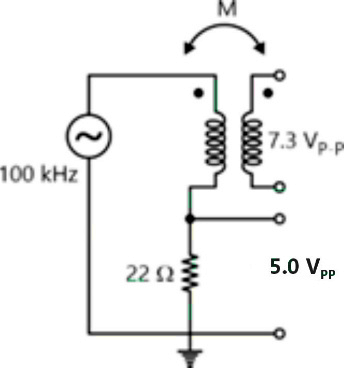
Sign in to UnlockAn air-core radio-frequency transformer as shown has a primary winding and a secondary winding. The mutual inductance M between the windings of the transformer is __________ μH. (Round off to 2 decimal places.)
Sign in to see the solution
Log in to view the explanation, track your attempts, and keep your progress.
Sign in to UnlockA single-phase, 4 kVA, 200 V/100 V, 50 ~Hz transformer with laminated CRGO steel core has rated no-load loss of 450 W. When the high-voltage winding is excited with 160 V, 40 Hz sinusoidal AC supply, the no-load losses are found to be 320 W. When the high-voltage winding of the same transformer is supplied from a 100 V, 25 Hz sinusoidal AC source, the no-load losses will be …………… W (rounded off to 2 decimal places).
Sign in to see the solution
Log in to view the explanation, track your attempts, and keep your progress.
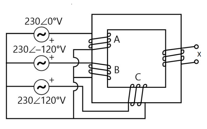
Sign in to UnlockWindings 'A', 'B' and 'C' have 20 turns each and are wound on the same iron core as shown, along with winding 'X which has 2 turns. The figure shows the sense (clockwise/anti-clockwise) of each of the windings only and does not reflect the exact number of turns, If windings 'A', 'B' and 'C' are supplied with balanced 3 -phase voltages at 50 Hz and there is no core saturation, the no-load RMS voltage (in V, rounded off to 2 decimal places) across winding ' X is ____________
Sign in to see the solution
Log in to view the explanation, track your attempts, and keep your progress.
Sign in to UnlockA 5 kVA, 50 V/100 V, single-phase transformer has a secondary terminal voltage of 95 V when loaded. The regulation of the transformer is.
Sign in to see the solution
Log in to view the explanation, track your attempts, and keep your progress.
Sign in to UnlockA single-phase transformer of rating 25 kVA, supplies a 12 kW load at power factor of 0.6 lagging. The additional load at unity power factor in kW (round off to two decimal places) that may be added before this transformer exceeds its rated kVA is __________.
Sign in to see the solution
Log in to view the explanation, track your attempts, and keep your progress.
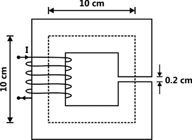
Sign in to UnlockThe magnetic circuit shown below has uniform cross-sectional area and air gap of 0.2 cm. The mean path length of the core is 40 cm. Assume that leakage and fringing fluxes are negligible. When the core relative permeability is assumed to be infinite, the magnetic flux density computed in the air gap is 1 tesla. With same Ampere-turns, if the core relative permeability is assumed to be 1000 (linear), the flux density in tesla (round off to three decimal places) calculated in the air gap is ____________.
Sign in to see the solution
Log in to view the explanation, track your attempts, and keep your progress.
Sign in to UnlockA single-phase 100kVA, 1000V/100 V. 50 Hz transformer has a voltage drop of 5% across its series impedance at full load. Of this, 3% is due to resistance. The percentage regulation of the transformer at full load with 0.8 lagging power factor is
Sign in to see the solution
Log in to view the explanation, track your attempts, and keep your progress.
Sign in to UnlockA 3-phase 900kVA, , 50Hz transformer has primary (high voltage side) resistance per phase of and secondary (low voltage side) resistance per phase of . Iron loss of the transformer is 10kW. The full load % efficiency of the transformer operated at unity power factor is ______ (up to 2 decimal places).


Sign in to see the solution
Log in to view the explanation, track your attempts, and keep your progress.
Sign in to UnlockA three-phase, three winding (1.1 kV/6.6 kV/400 V) transformer is energized from AC mains at the 1.1 kV side. It supplies 900 kVA load at 0.8 power factor lag from the 6.6 kV winding and 300 kVA load at 0.6 power factor lag from the 400 V winding. The RMS line current in ampere drawn by the 1.1 kV winding from the mains is ____________.

(Given the answer up to one decimal place).
Sign in to see the solution
Log in to view the explanation, track your attempts, and keep your progress.
Sign in to UnlockIf the primary line voltage rating is 3.3 kV (Y side) of a 25 kVA, transformer (the per phase turns ratio is 5:1), then the line current rating of the secondary side (in Ampere) is ____________ .

Sign in to see the solution
Log in to view the explanation, track your attempts, and keep your progress.
Sign in to UnlockIf an ideal transformer has an inductive load element at port 2 as shown in the figure below, the equivalent inductance at port 1 is
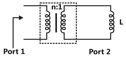
nL


Sign in to see the solution
Log in to view the explanation, track your attempts, and keep your progress.
Sign in to UnlockIf the star side of the star-delta transformer shown in the figure is excited by a negative sequence voltage then,
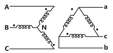
leads by


lags by
leads by

lags by
Sign in to see the solution
Log in to view the explanation, track your attempts, and keep your progress.
Sign in to UnlockA single-phase 400V, 50Hz transformer has an iron loss of 5000W at the rated condition. When operated at 200V, 25Hz, the iron loss is 2000W. When operated at 416V, 52Hz, the value of the hysteresis loss divided by the eddy current loss is _______.
Sign in to see the solution
Log in to view the explanation, track your attempts, and keep your progress.
Sign in to UnlockA single-phase, 22KVA, 2200V/220V, 50Hz, distribution transformer is to be connected as an auto-transformer to get an output voltage of 2420V. Its maximum KVA rating as an auto-transformer is
Sign in to see the solution
Log in to view the explanation, track your attempts, and keep your progress.
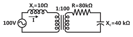
Sign in to UnlockThe following figure shows the connections of an ideal transformer with primary to secondary turns ratio of 1:100. The applied primary voltage is 100V (rms), 50Hz, AC. The rms value of the current I, in ampere, is ____________.
Sign in to see the solution
Log in to view the explanation, track your attempts, and keep your progress.
Sign in to UnlockA single-phase, 2kVA, 100/200 V transformer is reconnected as an auto-transformer such that its kVA rating is maximum. The new rating, in kVA, is ___________.
Sign in to see the solution
Log in to view the explanation, track your attempts, and keep your progress.
Sign in to UnlockThree-phase transformers are connected to form a delta-star three-phase transformer of . The transformer supplies at 11kV a load of 8 MW at 0.8 p.f. lagging to a nearby plant. Neglect the transformer losses. The ratio of phase current in delta to star side is


Sign in to see the solution
Log in to view the explanation, track your attempts, and keep your progress.
Sign in to UnlockThe self-inductance of the primary winding of a single phase, 50 Hz, transformer is 800 mH, and that of the secondary winding is 600 mH. The mutual inductance between these two windings is 480 mH. The secondary winding of this transformer is short circuited and the primary winding is connected to a 50 Hz, single phase, sinusoidal voltage source. The current flowing in both the windings is less than their respective rated currents. The resistance of both windings can be neglected. In this condition, what is the effective inductance (in mH) seen by the source?
Sign in to see the solution
Log in to view the explanation, track your attempts, and keep your progress.
Sign in to UnlockThe primary mmf is least affected by the secondary terminal conditions in a
Sign in to see the solution
Log in to view the explanation, track your attempts, and keep your progress.
Sign in to UnlockA 200/400V, 50 Hz, two-winding transformer is rated at 20 kVA. Its windings are connected as an auto-transformer of rating 200/600 V. A resistive load of 12 Ω is connected to the high voltage (600V) side of the auto-transformer. The value of equivalent load resistance (in Ohm) as seen from low voltage side is _____________.
Sign in to see the solution
Log in to view the explanation, track your attempts, and keep your progress.
Sign in to UnlockTwo single-phase transformers and each rated at 500 kVA are operated in parallel. Percentage impedances of and are (1 + j6) and (0.8 + j4.8), respectively. To share a load of 1000 kVA at 0.8 lagging power factor, the contribution of (in kVA) is ______________


Sign in to see the solution
Log in to view the explanation, track your attempts, and keep your progress.
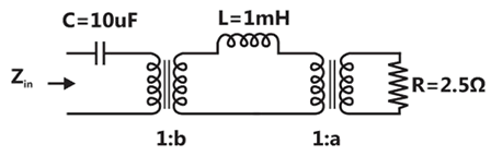
Sign in to UnlockFind the transformer ratios a and b such that the impedance ( ) is resistive and equals when the network is excited with a sine wave voltage of angular frequency of 5000 rad/s.


Sign in to see the solution
Log in to view the explanation, track your attempts, and keep your progress.
Sign in to UnlockA balanced (positive sequence) three-phase AC voltage source is connected to a balanced, star connected load through a star-delta transformer as shown in the figure. The line-to-line voltage rating is 230 V on the star side, and 115 V on the delta side. If the magnetizing current is neglected and A, then what is the value of in Ampere?


Sign in to see the solution
Log in to view the explanation, track your attempts, and keep your progress.
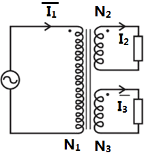
Sign in to UnlockA three-winding transformer is connected to an AC voltage source as shown in the figure. The number of turns are as follows: . If the magnetizing current is neglected, and the currents in two windings are = and = A, then what is the value of the current in Ampere?


Sign in to see the solution
Log in to view the explanation, track your attempts, and keep your progress.
Sign in to UnlockTwo three-phase transformers are realized using single-phase transformers as shown in the figure.
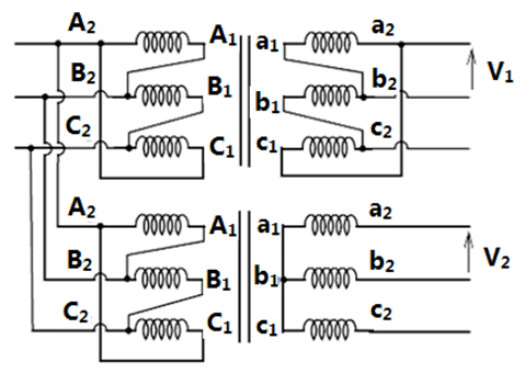
The phase difference (in degree) between voltages and is ___________.


Sign in to see the solution
Log in to view the explanation, track your attempts, and keep your progress.
Sign in to UnlockFor a specified input voltage and frequency, if the equivalent radius of the core of a transformer is reduced by half, the factor by which the number of turns in the primary should change to maintain the same no load current is
Sign in to see the solution
Log in to view the explanation, track your attempts, and keep your progress.
Sign in to UnlockThe core loss of a single phase, 230/115 V, 50Hz power transformer is measured from 230V side by feeding the primary (230V side) from a variable voltage frequency source while keeping the secondary open circuited. The core loss is measured to be 1050 W for 230V, 50Hz input. The core loss is again measured to be 500W for 138V, 30Hz input. The hysteresis and eddy current losses of the transformer for 230V, 50Hz input are respectively,
Sign in to see the solution
Log in to view the explanation, track your attempts, and keep your progress.
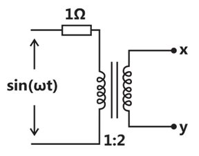
Sign in to UnlockAssuming an ideal transformer, the Thevenin’s equivalent voltage and impedance as seen from the terminals x and y for the circuit in figure are


Sign in to see the solution
Log in to view the explanation, track your attempts, and keep your progress.
Sign in to UnlockA single phase, 50kVA, 1000V/100V two winding transformer is connected as an autotransformer as shown in the figure.
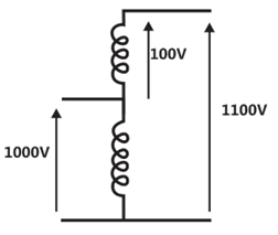
The kVA rating of the autotransformer is ________________.
Sign in to see the solution
Log in to view the explanation, track your attempts, and keep your progress.
Sign in to UnlockFor a single phase, two windings transformer, the supply frequency and voltage are both increased by 10%. The percentage changes in the hysteresis loss and eddy current loss, respectively, are
Sign in to see the solution
Log in to view the explanation, track your attempts, and keep your progress.
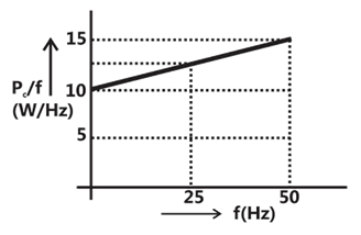
Sign in to UnlockAn open circuit test is performed on 50Hz transformer, using variable frequency source and keeping V/f ratio constant, to separate its eddy current and hysteresis losses. The variation of core loss/frequency as function of frequency is shown in the figure The hysteresis and eddy current losses of the transformer at 25Hz respectively are
Sign in to see the solution
Log in to view the explanation, track your attempts, and keep your progress.
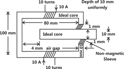
Sign in to UnlockThe load shown in the figure absorbs 4kW at a power factor of 0.89 lagging.
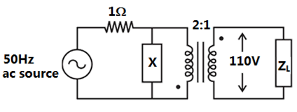
Assuming the transformer to be ideal, the value of the reactance X to improve the input power factor to unity is ________________.
Sign in to see the solution
Log in to view the explanation, track your attempts, and keep your progress.
Sign in to UnlockThe parameters measured for a 220V/110V, 50Hz, single-phase transformer are:
Self inductance of primary winding = 45mH
Self inductance of secondary winding = 30mH
Mutual inductance between primary and secondary windings = 20mH
using the above parameters, the leakage and magnetizing inductance as referred to primary side in the equivalent circuit respectively, are


Sign in to see the solution
Log in to view the explanation, track your attempts, and keep your progress.
Sign in to UnlockA single-phase transformer has no-load loss of 64W, as obtained from an open-circuit test. When a short-circuit test is performed on it with 90% of the rated currents flowing in its both LV and HV windings, the measured loss is 81W. The transformer has maximum efficiency when operated at
Sign in to see the solution
Log in to view the explanation, track your attempts, and keep your progress.
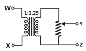
Sign in to UnlockThe following arrangement consists of an ideal transformer and an attenuator which attenuates by a factor of 0.8. An ac voltage is applied across WX to get an open circuit voltage across YZ. Next, an ac voltage is applied across YZ to get an open circuit voltage across WX. Then, are respectively,


Sign in to see the solution
Log in to view the explanation, track your attempts, and keep your progress.
Sign in to UnlockA single phase 10kVA, 50Hz transformer with 1kV primary winding draws 0.5A and 55W, at rated voltage and frequency, on no load. A second transformer has a core with all its linear dimensions times the corresponding dimensions of the first transformer. The core material and lamination thickness are the same in both transformers. The primary windings of both the transformers have the same number of turns. If a rated voltage of 2kV at 50Hz is applied to the primary of the second transformer, then the no load current and power, respectively, are

Sign in to see the solution
Log in to view the explanation, track your attempts, and keep your progress.
Sign in to UnlockA single-phase air core transformer, fed from a rated sinusoidal supply, is operating at no load. The steady state magnetizing current drawn by the transformer from the supply will have the waveform
Sign in to see the solution
Log in to view the explanation, track your attempts, and keep your progress.
Sign in to UnlockA single-phase transformer has a turns ratio of 1:2 and is connected to a purely resistive load as shown in the figure. The magnetizing current drawn is 1 A, and the secondary current is 1 A. If core losses and leakage reactance are neglected, the primary current is
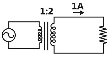
Sign in to see the solution
Log in to view the explanation, track your attempts, and keep your progress.
Sign in to UnlockA balanced star-connected and purely resistive load is connected at the secondary of a star-delta transformer as shown in the figure. The line-to-line voltage rating of the transformer is 110V/220V. Neglecting the non-idealities of the transformer, the impedance ‘Z’ of the equivalent star-connected load, referred to the primary side of the transformer, is:
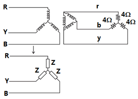


Sign in to see the solution
Log in to view the explanation, track your attempts, and keep your progress.
Sign in to UnlockThe single phase, 50Hz, iron core transformer in the circuit has both the vertical arms of cross sectional area and both the horizontal arms of cross sectional area . If the two windings shown were wound instead on opposite horizontal arms, the mutual inductances will


Sign in to see the solution
Log in to view the explanation, track your attempts, and keep your progress.
Sign in to Unlock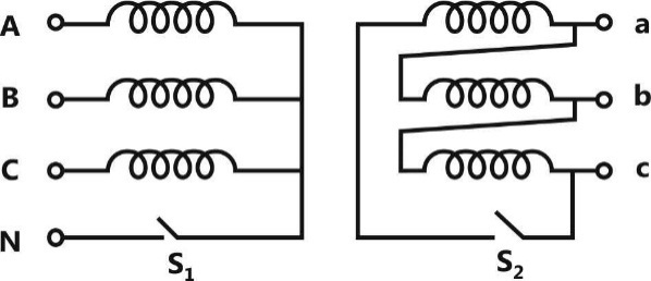
With both S1 and S2 open, the core flux waveform will be
Sign in to see the solution
Log in to view the explanation, track your attempts, and keep your progress.
Sign in to UnlockWith S2 closed and S1 open, the current waveform in the delta winding will be
Sign in to see the solution
Log in to view the explanation, track your attempts, and keep your progress.
Sign in to Unlock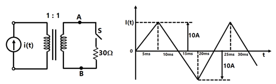
The circuit diagram shows a two-winding, loss less transformer with no leakage flux, excited from a current source, i(t), whose waveform is also shown. The transformer has a magnetizing inductance of 400/π mH.
The peak voltage across A and B, with S open is
Sign in to see the solution
Log in to view the explanation, track your attempts, and keep your progress.
Sign in to UnlockThe circuit diagram shows a two-winding, loss less transformer with no leakage flux, excited from a current source, i(t), whose waveform is also shown. The transformer has a magnetizing inductance of 400/π mH.
If the waveform of i(t) is changed to , the peak voltage across A and B with S closed is

Sign in to see the solution
Log in to view the explanation, track your attempts, and keep your progress.
Sign in to UnlockThe figure below shows coils 1 and 2, with dot markings as shown, having 4000 and 6000 turns respectively. Both the coils have a rated current of 25 A. Coil 1 is excited with single phase, 400 V, 50 Hz supply.
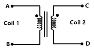
The coils are to be connected to obtain a single phase, 400/1000 V, auto-transformer to drive a load of 10kVA. Which of the options given should be exercised to realize the required auto-transformer?
Sign in to see the solution
Log in to view the explanation, track your attempts, and keep your progress.
Sign in to UnlockThe figure below shows coils 1 and 2, with dot markings as shown, having 4000 and 6000 turns respectively. Both the coils have a rated current of 25 A. Coil 1 is excited with single phase, 400 V, 50 Hz supply.
In the autotransformer obtained in Question 57, the current in each coil is
Sign in to see the solution
Log in to view the explanation, track your attempts, and keep your progress.
Sign in to UnlockThree single-phase transformers are connected to form a 3-phase transformer bank. The transformers are connected in the following manner:
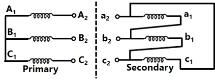
The transformer connection will be represented by
Sign in to see the solution
Log in to view the explanation, track your attempts, and keep your progress.
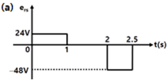
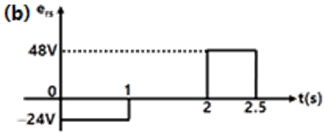
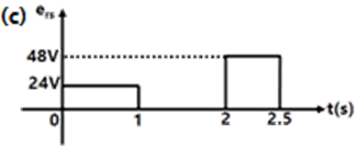
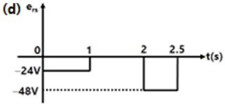
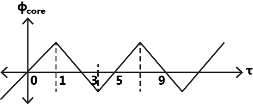
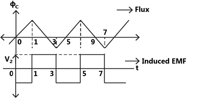
Sign in to UnlockThe core of a two-winding transformer is subjected to a magnetic flux variation as indicated in the figure.
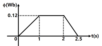
The induced emf in the secondary winding as a function of time will be of the form

Sign in to see the solution
Log in to view the explanation, track your attempts, and keep your progress.
Sign in to UnlockIt is desired to measure parameters of 230V / 115V, 2kVA, single-phase transformer. The following watt-meters are available in a laboratory:
: 250V, 10A. Low Power Factor

: 250V, 5A. Low Power Factor

: 150V, 10A. High Power Factor

: 150V, 5A. High Power Factor

The watt-meters used in open circuit test and short circuit test of the transformer will respectively be


Sign in to see the solution
Log in to view the explanation, track your attempts, and keep your progress.
Sign in to UnlockIn a transformer zero voltage regulation at full load is
Sign in to see the solution
Log in to view the explanation, track your attempts, and keep your progress.
Sign in to UnlockA single-phase 50kVA, 250V/500V two winding transformer has an efficiency of 95% at full load, unity power factor. If it is reconfigured as a 500V/750V autotransformer, its efficiency at its new rated load at unity power factor will be
Sign in to see the solution
Log in to view the explanation, track your attempts, and keep your progress.
Sign in to UnlockIn the figure, transformer , has two secondary, all three windings having the same number of tums and with polarities as indicated. One secondary is shorted by a 10 Ω resistor R, and the other by a 15 µF capacitor. The switch SW is opened (t = 0) when the capacitor is charged to 5V with the left plate as positive. At t=0+ the voltage and current are


Sign in to see the solution
Log in to view the explanation, track your attempts, and keep your progress.
Sign in to UnlockIn transformers, which of the following statements is valid?
Sign in to see the solution
Log in to view the explanation, track your attempts, and keep your progress.
Sign in to UnlockTwo transformers are to be operated in parallel such that they share load in proportion to their kVA ratings. The rating of the first transformer is 500 kVA and its pu leakage impedance is 0.05 pu. If the rating of second transformer is 250 kVA, then its pu leakage impedance is
Sign in to see the solution
Log in to view the explanation, track your attempts, and keep your progress.
Sign in to UnlockA 300 kVA transformer has 95% efficiency at full load 0.8 pf lagging and 96% efficiency at half load, unity pf.
The iron loss and copper loss in kW, under full load operation are


= 4.12, = 8.51


= 6.59, = 9.21
= 8.51, = 4.12
= 12.72, = 3.07
Sign in to see the solution
Log in to view the explanation, track your attempts, and keep your progress.
Sign in to UnlockA 300 kVA transformer has 95% efficiency at full load 0.8 pf lagging and 96% efficiency at half load, unity pf.
What is the maximum efficiency (in %) at unity pf load?
Sign in to see the solution
Log in to view the explanation, track your attempts, and keep your progress.
Sign in to UnlockWhich three-phase connection can be used in a transformer to introduce a phase difference of 30° between its output and corresponding input line voltages
Sign in to see the solution
Log in to view the explanation, track your attempts, and keep your progress.
Sign in to UnlockThe equivalent circuit of a transformer has leakage reactance and magnetizing reactance . Their magnitudes satisfy


Sign in to see the solution
Log in to view the explanation, track your attempts, and keep your progress.
Sign in to UnlockA 500 kVA, 3-phase transformer has iron loses of 300 W and full load copper losses of 600 W. The percentage load at which the transformer is expected to have maximum efficiency
Sign in to see the solution
Log in to view the explanation, track your attempts, and keep your progress.
Sign in to UnlockA 50 kVA, 3300/230V single-phase transformer is connected as an autotransformer shown in figure. The nominal rating of the autotransformer will be

Sign in to see the solution
Log in to view the explanation, track your attempts, and keep your progress.
Sign in to UnlockThe resistance and reactance of a 100 kVA 11000/400V, Δ-Y distribution transformer are 0.02 and 0.07pu respectively. The phase impedance of the transformer referred to the primary is
Sign in to see the solution
Log in to view the explanation, track your attempts, and keep your progress.
Sign in to UnlockA single phase transformer has a maximum efficiency of 90% at full load and unity power factor. Efficiency at half load at the same power factor is
Sign in to see the solution
Log in to view the explanation, track your attempts, and keep your progress.
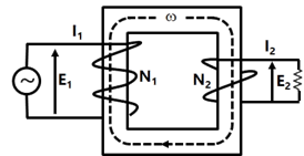
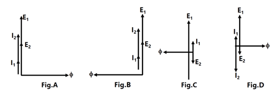
Sign in to UnlockFigure shows an ideal single-phase transformer. The primary and secondary coils are wound on the core as shown. Turns ratio . The correct phasors of voltages currents and core flux φ are as shown in


Sign in to see the solution
Log in to view the explanation, track your attempts, and keep your progress.
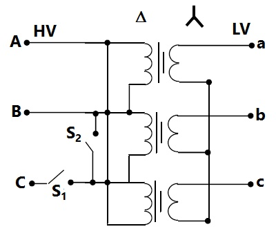
Sign in to UnlockFigure shows a Δ-Y connected 3-phase distribution transformer used to step down the voltage from 11000 V to 415 V line-to line. It has two switches and . Under normal conditions is closed and is open. Under certain special conditions is open and is closed. In such a case the magnitude of the voltage across the LV terminals a and c is


Sign in to see the solution
Log in to view the explanation, track your attempts, and keep your progress.
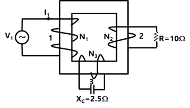
Sign in to UnlockFigure shows an ideal three-winding transformer. The three windings 1, 2, 3 of the transformer are wound on the same core as shown. The turn’s ratio is 4:2:1. A resistor of 10Ω is connected across winding-2. A capacitor of reactance 2.5Ω is connected across winding-3. Widing-1 is connected across a 400 V, ac supply. If the supply voltage phasor = 400∠0°, the supply current phasor is given by


Sign in to see the solution
Log in to view the explanation, track your attempts, and keep your progress.
Sign in to UnlockA 1 kVA, 230V/100V, single phase, 50 Hz transformer having negligible winding resistance and leakage inductance is operating under saturation, while 250 V, 50 Hz sinusoidal supply is connected to the high voltage winding. A resistive load is connected to the low voltage winding which draws rated current. Which one of the following quantities will not be sinusoidal?
Sign in to see the solution
Log in to view the explanation, track your attempts, and keep your progress.
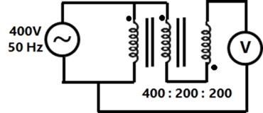
Sign in to UnlockA 400V/200V/200V, 50 Hz three winding transformer is connected as shown in Figure. The reading of the voltmeter, V, will be
Sign in to see the solution
Log in to view the explanation, track your attempts, and keep your progress.
Sign in to UnlockA single phase 6300kVA, 50 Hz, 3300V/400V distribution transformer is connected between two 50 Hz supply systems, A and B as shown in Figure, the transformer has 12 and 99 turns in the low and high voltage windings respectively. The magnetizing reactance of the transformer referred to the high voltage side is 500Ω. The leakage reactance of the high and low voltage windings are 1.0Ω and 0.012Ω respectively. Neglect the winding resistance and core losses of the transformer. The Thevenin voltage of system A is 3300V while that of system B is 400 V, the short circuit reactance of systems A and B are 0.5Ω and 0.010 Ω respectively. If no power is transferred between A and B, so that the two system voltages are in phase, find the magnetizing ampere turns of the transformer.

Sign in to see the solution
Log in to view the explanation, track your attempts, and keep your progress.
Sign in to UnlockA single-phase transformer is to be switched to the supply to have minimum inrush current. The switch should be closed be
Maximum supply voltage
Zero supply voltage
maximum supply voltage

maximum supply voltage

Sign in to see the solution
Log in to view the explanation, track your attempts, and keep your progress.
Sign in to UnlockThe core flux of a practical transformer with a resistive load
Sign in to see the solution
Log in to view the explanation, track your attempts, and keep your progress.
Sign in to UnlockThe hysteresis loop of a magnetic material has an area of 5 with the scales given as 1 cm = 2AT and 1 cm = 50mWb. At 50 Hz, the total hysteresis loss is

Sign in to see the solution
Log in to view the explanation, track your attempts, and keep your progress.
Sign in to UnlockA 3-phase transformer has rating of 20 MVA, 200 kV (star)–33 kV (delta) with leakage reactance of 12%. The transformer reactance (in ohms) referred to each phase of the L.V delta-connected side is
Sign in to see the solution
Log in to view the explanation, track your attempts, and keep your progress.
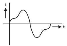
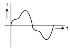
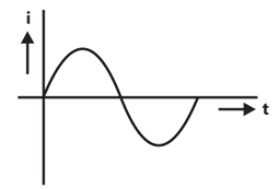
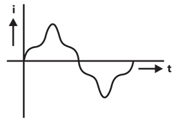
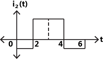
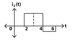
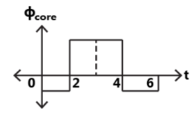
Sign in to UnlockAn ideal transformer has a linear B-H characteristic with a finite slope and a turns ratio 1:1. The primary of the transformer is energized with an ideal current source, producing the signal I as shown in figure. Sketch the shape (neglecting the scale factor) of the following signals, labeling the time axis clearly:
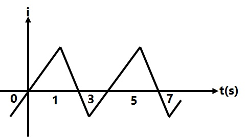
(a) The core flux with the secondary of the transformer open
(b) The open-circuited secondary terminal voltage
(c) The short-circuited secondary current
(d) The core flux with the secondary of the transformer short-circuited.


(a)
(b)
(c)
(d)
(a)
(b)
(c)
(d)
(a)
(b)
(c)
(d)
None
Sign in to see the solution
Log in to view the explanation, track your attempts, and keep your progress.
Sign in to UnlockIn a constant voltage transformer (CVT), the output voltage remains constant due to
Sign in to see the solution
Log in to view the explanation, track your attempts, and keep your progress.
Sign in to UnlockA 3-phase delta/star transformer is supplied at 6000V on the delta-connected side. The terminal voltage on the secondary side when supplying full load as 0.8 lagging power-factor is 415V. The equivalent resistance and reactance drops for the transformer are 1% and 5% respectively. The turns ratio of the transformer is:
Sign in to see the solution
Log in to view the explanation, track your attempts, and keep your progress.
Sign in to UnlockIn a single-phase, three –winding transformer, the turns ratio for primary: secondary : tertiary windings is 20:4:1. With the lagging currents of 50A at a power factor of 0.6 in the tertiary winding, find the magnitude of primary current and power-factor.
Sign in to see the solution
Log in to view the explanation, track your attempts, and keep your progress.
Sign in to UnlockThe winding of a Q kVA, volt, three-phase, Delta connected, core type transformer are reconnected to work as a single phase transformer. The maximum voltage and the power ratings of the new configuration are


Sign in to see the solution
Log in to view the explanation, track your attempts, and keep your progress.
Sign in to UnlockA 10kVA, 400 V/200V single-phase transformers with 10% impedance draws a steady short circuit line current of
Sign in to see the solution
Log in to view the explanation, track your attempts, and keep your progress.
Sign in to UnlockThe percentage resistance and percentage reactance of a 10kVA, 400V/200V, 3-phase transformer are 2% and 10% respectively. If the constant losses in the machine are 1%, the maximum possible percentage efficiency of the transformer is:
Sign in to see the solution
Log in to view the explanation, track your attempts, and keep your progress.
Sign in to UnlockA 400V/100V, 10 kVA two-winding transformer is reconnected as an auto-transformer across a suitable voltage source. The maximum rating of such an arrangement could be
Sign in to see the solution
Log in to view the explanation, track your attempts, and keep your progress.
Sign in to UnlockA 10 kVA, 400V/200V, single transformer with a percentage resistance of 3% and percentage reactance of 6% is supplying a current of 50A to a resistive load. The value of the load voltage is:
Sign in to see the solution
Log in to view the explanation, track your attempts, and keep your progress.
Sign in to UnlockTwo single-phase transformers A and B have the following parameters:
Transformer A: 10V/200V, percentage resistance and percentage reactance 3% and 4% respectively.
Transformer B: 5 kVA, 400V/200V, percentage resistance and percentage reactance are 4% and 3% respectively.
These two transformers are connected in parallel and they share a common load of 12 kW at a power factor of 0.8 lagging. Determine the active and reactive power delivered by the transformer A.


Sign in to see the solution
Log in to view the explanation, track your attempts, and keep your progress.
Sign in to UnlockThe efficiency of a 100KVA transformer is 0.98 at full as well as at half load. For this transformer at full load the copper loss
Sign in to see the solution
Log in to view the explanation, track your attempts, and keep your progress.
Sign in to UnlockThe magnetizing current in a transformer is rich in
harmonic

harmonic

harmonic

harmonic

Sign in to see the solution
Log in to view the explanation, track your attempts, and keep your progress.
Sign in to UnlockA 50Hz transformer having equal hysteresis and eddy current losses at rated excitation is operated at 45Hz at 90% of its rated voltage. Compared to rated operating point, the core losses under this condition:
Sign in to see the solution
Log in to view the explanation, track your attempts, and keep your progress.
Sign in to UnlockIn a 50 KVA, 11 KV/400V transformers, the iron and copper losses are 500W and 600W respectively under rated conditions. Calculate the efficiency on unity power factor at full load. Find the load for maximum efficiency and the iron and copper losses corresponding to this load.
Sign in to see the solution
Log in to view the explanation, track your attempts, and keep your progress.
Sign in to UnlockThe low voltage winding of a 400/230V, 1-phase, 50Hz transformer is to be connected to a 25Hz supply, the supply voltage should be
Sign in to see the solution
Log in to view the explanation, track your attempts, and keep your progress.
Sign in to UnlockA voltage v=400sin(314.16t) is applied to a 1-phase transformer on no-load. If the no load current of the transformer is 2sin(314.16t-85°), then magnetization branch impedance will be approximately equal to


Sign in to see the solution
Log in to view the explanation, track your attempts, and keep your progress.
Sign in to UnlockA 3-phase transformer bank consists of three identical 2300/230V, 15 kVA single-phase transformers connect in delta/delta. The bank supplies a 20 kVA, unity p.f. 3-phase load. If one of the single-phase transformer develops a fault, and is removed, the load carried by each of the two transformers now operating in open delta will be… kVA.
Sign in to see the solution
Log in to view the explanation, track your attempts, and keep your progress.
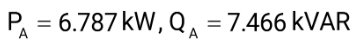
Sign in to UnlockGiven figure shows a magnetic circuit formed by an ideal core material. Determine the magnetic flux density in the air gap.
Sign in to see the solution
Log in to view the explanation, track your attempts, and keep your progress.
Sign in to UnlockThe function of oil in a transformer is
Sign in to see the solution
Log in to view the explanation, track your attempts, and keep your progress.
Sign in to UnlockAuto-transformer is used in transmission and distribution
Sign in to see the solution
Log in to view the explanation, track your attempts, and keep your progress.
Sign in to UnlockKeeping in view the requirement of parallel operation, which of the 3-phase connections given below are possible?
Sign in to see the solution
Log in to view the explanation, track your attempts, and keep your progress.
Sign in to UnlockSupply to one terminal of a delta-wye connected three-phase core type transformer which is on no-load, fails. Assuming magnetic circuit symmetry, voltages on the secondary side will be:
Sign in to see the solution
Log in to view the explanation, track your attempts, and keep your progress.
Sign in to UnlockWhen started by means of an auto-transformer with 50% tapping, supply current at start of an induction motor is reduced to ______________ of that when started by means of a star-delta starter.
Sign in to see the solution
Log in to view the explanation, track your attempts, and keep your progress.
Sign in to UnlockThe percentage impedance of a 100 kVA, 11 kV/400V, delta/wye, 50Hz transformer is 4.5%. For the circulation of half the full load current during short circuit test, with low voltage terminals shorted, the applied voltage on the high voltage side will be ________.
Sign in to see the solution
Log in to view the explanation, track your attempts, and keep your progress.
Sign in to UnlockA 4 kVA, 50 Hz, single-phase transformer has a ratio 200/400V. the data taken on the l.v. side at the rated voltage show that the open circuit input wattage is 80W. The mutual inductance between the primary and the secondary windings is 1.91H. What value will be the current taken by the transformer, if the no-load test is conducted on the h.v. side at rated voltage? Neglect the effect of winding resistance and leakage reactances.
Sign in to see the solution
Log in to view the explanation, track your attempts, and keep your progress.
Sign in to UnlockTwo transformers of identical voltages but of different capacities are operating in parallel. For satisfactory load sharing
Impedances must be equal
Per-unit impedances must be equal
Per-unit impedances and rations must be equal

Impedances and ratios must be equal
Sign in to see the solution
Log in to view the explanation, track your attempts, and keep your progress.
Sign in to UnlockA 220/440 V, 50 Hz, 5 kVA single phase transformer operates on 220V, 40 Hz supply with secondary winding. Then
Sign in to see the solution
Log in to view the explanation, track your attempts, and keep your progress.
Sign in to UnlockTwo 550kVA alternators operate in parallel to supply the following loads
(i) 250 kW at 0.95 power factor lag
(ii) 100kW at 0.8 power factor lead
One machine is supplying 200kW at 0.9 pf lag. The power factor of other machine must be
Sign in to see the solution
Log in to view the explanation, track your attempts, and keep your progress.
Sign in to UnlockTwo transformers of the same type, using the same grade of iron and conductor materials, are designed to work at the same flux and current densities; but the linear dimensions of one are two times those of the other in all respects. The ratio of kVA of the two transformers closely equals
Sign in to see the solution
Log in to view the explanation, track your attempts, and keep your progress.
Sign in to UnlockTwo transformers of different kVA ratings working in parallel share the load in proportion to their ratings when their
Sign in to see the solution
Log in to view the explanation, track your attempts, and keep your progress.
Sign in to UnlockThe relative current directions through the Primary (P) and Secondary (S) of a single phase transformer connected to a resistive load on the secondary side, are indicated in the various cross-sectional views given in figure. Which of these are correct representations


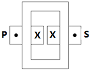
Sign in to see the solution
Log in to view the explanation, track your attempts, and keep your progress.
Sign in to UnlockThe hysteresis and eddy current losses of a single phase transformer working on 200V, 50 Hz supply are respectively. The percentage decrease in these, when operated on a 160V, 40 Hz supply are :

Sign in to see the solution
Log in to view the explanation, track your attempts, and keep your progress.
Sign in to UnlockA toroidal iron ring has a uniform cross-sectional area of 50, and a mean magnetic path length of 100mm. the ring has an air-gap of 1mm, the ring is excited with a dc current of 1 A through a coil of 100 turns wound uniformly along its length. The iron may be assumed to be perfect magnetic material. The effect of fringing at the gap may be assumed to increase the effective area of magnetic flux at the gap by 10%.

Evaluate
(a) The exciting mmf of the coil
(b) The effective reluctance of magnetic circuit
(c) The inductance of the coil
(d) The energy stored in the magnetic field under the above excitation.
Sign in to see the solution
Log in to view the explanation, track your attempts, and keep your progress.
Sign in to Unlock