Power Systems
Transmission and Distribution
Practice questions from Transmission and Distribution.
140
Total0
Attempted0
Correct0
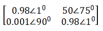
IncorrectFor the balanced 3-phase transmission line shown, consider the following cases:
Case-1: p.u., p.u., p.u. and


Case-2: p.u., p.u., p.u. and


Which of the following statements is/are correct about real power loss and reactive power loss in the line?
Sign in to see the solution
Log in to view the explanation, track your attempts, and keep your progress.
Sign in to UnlockConsider a distribution feeder, with ratio of 5. At the receiving end, a 350 kVA load is connected. The maximum voltage drop will occur from the sending end to the receiving end, when the power factor of the load is ________ (round off to three decimal places).

Sign in to see the solution
Log in to view the explanation, track your attempts, and keep your progress.
Sign in to UnlockUsing shunt capacitors, the power factor of a 3 -phase, 4 kV induction motor (drawing 390 kVA at 0.77 pf lag) is to be corrected to 0.85 pf lag. The line current of the capacitor bank, in A, is _________ (round off to one decimal place).
Sign in to see the solution
Log in to view the explanation, track your attempts, and keep your progress.
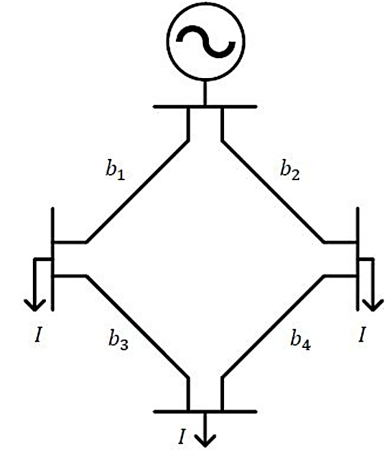
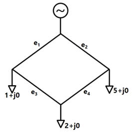
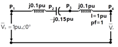
Sign in to UnlockThe figure shows the single line diagram of a 4-bus power network. Branches , , and have impedances , and per-unit (pu), respectively, where , with and . The current drawn from each load bus (marked as arrows) is equal to pu, where . If the network is to operate with minimum loss, the branch that should be opened is


Sign in to see the solution
Log in to view the explanation, track your attempts, and keep your progress.
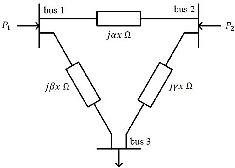
Sign in to UnlockFor the three-bus lossless power network shown in the figure, the voltage magnitudes at all the buses are equal to 1 per unit , and the differences of the voltage phase angles are very small. The line reactances are marked in the figure, where , and are strictly positive. The bus injections and are in pu. If , where , and the real power flow from bus 1 to bus 2 is , then which one of the following options is correct?


Sign in to see the solution
Log in to view the explanation, track your attempts, and keep your progress.
Sign in to UnlockA line of length has the following parameters:


Resistance,
Inductance, ;

Capacitance,

The line is represented by the nominal- model. With the magnitudes of the sending end and the receiving end voltages of the line (denoted by and , respectively) maintained at , the phase angle difference between and required for maximum possible active power to be delivered to the receiving end, in degree is ________ (Round off to 2 decimal places).


Sign in to see the solution
Log in to view the explanation, track your attempts, and keep your progress.
Sign in to UnlockThe geometric mean radius of a conductor, having four equal strands with each strand of radius ‘𝑟’, as shown in the figure below, is

Sign in to see the solution
Log in to view the explanation, track your attempts, and keep your progress.
Sign in to UnlockIf only 5% of the supplied power to a cable reaches the output terminal, the power loss in the cable, in decibels, is _________. (round off to nearest integer)
Sign in to see the solution
Log in to view the explanation, track your attempts, and keep your progress.
Sign in to UnlockTwo single-core power cables have total conductor resistances of 0.7 Ω and 0.5 Ω, respectively, and their insulation resistances (between core and sheath) are 600 MΩ and 900 MΩ, respectively. When the two cables are joined in series, the ratio of insulation resistance to conductor resistance is ______

Sign in to see the solution
Log in to view the explanation, track your attempts, and keep your progress.
Sign in to UnlockAn alternator with internal voltage of . and synchronous reactance of 0.4 p.u is connected by a transmission line of reactance 0.1 p.u. to a synchronous motor having synchronous reactance 0.35 pu. and internal voltage of If the real power supplied by the altemator is 0.866 p.u, then is …………… degrees. (Round off to 2 decimal places) (Machines are of non-salient type. Neglect resistances)


Sign in to see the solution
Log in to view the explanation, track your attempts, and keep your progress.
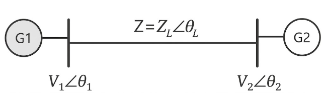
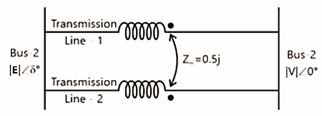
Sign in to UnlockIn the figure shown, self-impedances of the two transmission Iines are 1.5j p.u each, and is the mutual impedance. Bus voltages shown in the figure are in p.u. Given that , the maximum steady-state real power that can be transferred in p.u from Bus-1 to Bus-2 is


Sign in to see the solution
Log in to view the explanation, track your attempts, and keep your progress.
Sign in to UnlockA lossless transmission line with 0.2 pu reactance per phase uniformly distributed along the length of the line, connecting a generator bus to a load bus, is protected up to 80 % of its length by a distance relay placed at the generator bus. The generator terminal voltage is 1 pu. There is no generation at the load bus. The threshold pu current for operation of the distance relay for a solid three phase-to-ground fault on the transmission line is closest to:
Sign in to see the solution
Log in to view the explanation, track your attempts, and keep your progress.
Sign in to UnlockBus 1 with voltage magnitude is sending reactive power towards bus 2 with voltage magnitude through a lossless transmission line of reactance X. Keeping the voltage at bus 2 fixed at 1 pu, magnitude of voltage at bus 1 is changed, so that the reactive power sent from bus 1 is increased by


20%. Real power flow through the line under both the conditions is zero. The new value of the voltage magnitude, , in pu (rounded off to 2 decimal places), at bus 1 is __________.


Sign in to see the solution
Log in to view the explanation, track your attempts, and keep your progress.
Sign in to UnlockA three-phase 50Hz, 400kV transmission line is 300 km long. The line inductance is 1mH/phase and capacitance 0.01µF/km per phase. The line is under open circuit condition at receiving end and energized with 400kV at sending end, the receiving end line voltage is KV (round off to two decimal places) will be ______
Sign in to see the solution
Log in to view the explanation, track your attempts, and keep your progress.
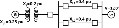
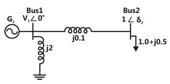
Sign in to UnlockIn the single machine infinite bus system shown below, the generator is delivering the real power of 0.8 pu at 0.8 power factor lagging to the infinite bus. The power angle of the generator in degrees (round off to one decimal place) is _________.
Sign in to see the solution
Log in to view the explanation, track your attempts, and keep your progress.
Sign in to UnlockConsider a lossy transmission line with and as the sending and receiving end voltages, respectively. Z and X are the series impedance and reactance of the line, respectively. The steady-state stability limit for the transmission line will be

Greater than

Less than
equal to
equal to
Sign in to see the solution
Log in to view the explanation, track your attempts, and keep your progress.
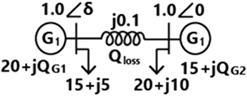
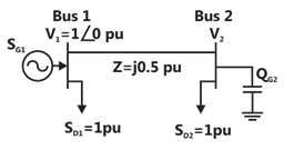
Sign in to UnlockConsider the two bus power system network with given loads as shown in the figure. All the values shown in the figure are in per unit. The reactive power supplied by generator and are and respectively. The per unit values of and line reactive power loss respectively are


Sign in to see the solution
Log in to view the explanation, track your attempts, and keep your progress.
Sign in to UnlockA load is supplied by a 230 V, 50 Hz source. The active power P and the reactive power Q consumed by the load are such that .and A capacitor connected across the load for power factor correction generates 1 kVAR reactive power. The worst case power factor after power factor correction is


Sign in to see the solution
Log in to view the explanation, track your attempts, and keep your progress.
Sign in to UnlockThe nominal- circuit of a transmission line is shown in the figure.

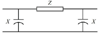
Impedance and reactance. The magnitude of the characteristic impedance of the transmission line, in , is ______________ . (Give the answer up to one decimal place)


Sign in to see the solution
Log in to view the explanation, track your attempts, and keep your progress.
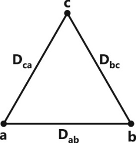
Sign in to UnlockConsider an overhead transmission line with 3-phase, 50 Hz balanced system with conductors located at the vertices of an equilateral triangle of length as shown in figure below. The resistances of the conductors are neglected. The geometric mean radius (GMR) of each conductor is 0.01 m. Neglecting the effect of ground, the magnitude of positive sequence reactance in (rounded off to three decimal places ) is ___________


Sign in to see the solution
Log in to view the explanation, track your attempts, and keep your progress.
Sign in to UnlockA 3-phase, 50 Hz generator supplies power of 3MW at 17.32 kV to a balanced 3-phase inductive load through an overhead line. The per phase line resistance and reactance are and respectively. If the voltage at the generator terminal is 17.87 kV, the power factor of the load is ___________ .


Sign in to see the solution
Log in to view the explanation, track your attempts, and keep your progress.
Sign in to UnlockA three-phase cable is supplying 800kW and 600 kVAr to an inductive load. It is intended to supply an additional resistive load of 100kW through the same cable without increasing the heat dissipation in the cable, by providing a three-phase bank of capacitors connected in star across the load. Given the line voltage is 3.3kV, 50Hz, the capacitance per phase of the bank, expressed in microfarads, is _______________.
Sign in to see the solution
Log in to view the explanation, track your attempts, and keep your progress.
Sign in to UnlockA single-phase transmission line has two conductors each of 10 mm radius. These are fixed at a center-to-center distance of 1m in a horizontal plane. This is now converted to a three-phase transmission line by introducing a third conductor of the same radius. This conductor is fixed at an equal distance D from the two single-phase conductors. The three phase line is fully transposed. This positive sequence inductance per phase of the three-phase system is to be 5% more than that of the inductance per conductor of the single-phase system. The distance D, in meters, is_________________.
Sign in to see the solution
Log in to view the explanation, track your attempts, and keep your progress.
Sign in to UnlockThe inductance and capacitance of a 400kV, three-phase, 50 Hz lossless transmission line are 1.6 mH/km/phase and 10 mF/km/phase respectively. The sending end voltage is maintained at 400kV. To maintain a voltage of 400kV at the receiving end, when the line is delivering 300MW load, the shunt compensation required is
Sign in to see the solution
Log in to view the explanation, track your attempts, and keep your progress.
Sign in to UnlockAt no load condition, a 3-phase, 50Hz, losses power transmission line has sending-end and receiving-end voltages of 400kV and 420kV respectively. Assuming the velocity of travelling wave to be the velocity of light, the length of the line, in km, is______________.
Sign in to see the solution
Log in to view the explanation, track your attempts, and keep your progress.
Sign in to UnlockThe power consumption of an industry is 500 kVA, at 0.8 p.f. lagging. A synchronous motor is added to raise the power factor of the industry to unity. If the power intake of the motor is 100 kW, the p.f. of the motor is_______________.
Sign in to see the solution
Log in to view the explanation, track your attempts, and keep your progress.
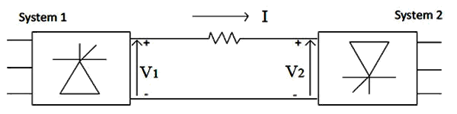
Sign in to UnlockConsider a HVDC link which uses thyristor based line- commutated converter as shown in the figure. For a power flow of 750 MW from system 1 to system 2, the voltages at the two ends, and the current are given by: =500 kV, and I=1.5 kA. If the direction of power flow is to be reversed (that is from system 2 to system 1) without changing the electrical connections, then which one of the following combinations is feasible?

and I = 1.5 kA

and I =1.5 kA

and I = – 1.5kA

and I = – 1.5 kA
Sign in to see the solution
Log in to view the explanation, track your attempts, and keep your progress.
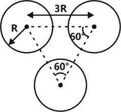
Sign in to UnlockA composite conductor consists of three conductors of radius R each. The conductors are arranged as shown below. The geometric mean radius (GMR) (in cm) of the composite conductor is kR. The value of k is ____________.
Sign in to see the solution
Log in to view the explanation, track your attempts, and keep your progress.
Sign in to UnlockThe undesirable property of an electrical insulating material is
Sign in to see the solution
Log in to view the explanation, track your attempts, and keep your progress.
Sign in to UnlockA distribution feeder of 1km length having resistance, but negligible reactance, is fed from both the ends by 400V, 50Hz balanced sources. Both voltage source are in phase. The feeder supplies concentrated loads of unity power factor as shown in the figure.

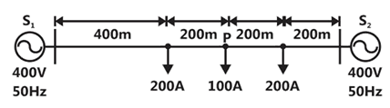
The contributions of and in 100A current supplied at location P respectively, are


Sign in to see the solution
Log in to view the explanation, track your attempts, and keep your progress.
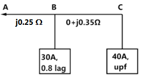
Sign in to UnlockA two bus power system shown in the figure supplies load of 1.0 + j0.5 p.u
The values of in p.u. and respectively are

0.95 and

1.05 and

1.1 and

1.1 and

Sign in to see the solution
Log in to view the explanation, track your attempts, and keep your progress.
Sign in to UnlockA single phase induction motor draws 12 MW power at 0.6 lagging power. A capacitor is connected in parallel to the motor to improve the power factor of the combination of motor and capacitor to 0.8 lagging. Assuming that the real and reactive power drawn by the motor remains same as before, the reactive power delivered by the capacitor in MVAR is ______________.
Sign in to see the solution
Log in to view the explanation, track your attempts, and keep your progress.
Sign in to UnlockA three phase star-connected load is drawing power at a voltage of 0.9 pu and 0.8 power factor lagging. The three phase base power and base current are 100 MVA and 437.38 A respectively. The line-to-line load voltage in kV is______________.
Sign in to see the solution
Log in to view the explanation, track your attempts, and keep your progress.
Sign in to UnlockShunt reactors are sometimes used in high voltage transmission systems to
Sign in to see the solution
Log in to view the explanation, track your attempts, and keep your progress.
Sign in to UnlockThe horizontally placed conductors of a single phase line operating at 50Hz are having outside diameter of 1.6cm, the spacing between centers of the conductors is 6m. The permittivity of free space is F/m. The capacitance to ground per kilometer of each line is


Sign in to see the solution
Log in to view the explanation, track your attempts, and keep your progress.
Sign in to UnlockIn a long transmission line with r, l, g and c are the resistance, inductance, shunt conductance and capacitance per unit length, respectively, the condition for distortion less transmission is
rc = lg

rg = lc

Sign in to see the solution
Log in to view the explanation, track your attempts, and keep your progress.
Sign in to UnlockFor a 400 km long transmission line, the series impedance is and the shunt admittance is μmho/km. The magnitude of the series impedance of the equivalent circuit of the transmission line is ____________.


Sign in to see the solution
Log in to view the explanation, track your attempts, and keep your progress.
Sign in to UnlockThe complex power consumed by a constant-voltage load is given by , where and .A compensating shunt capacitor is chosen such that , where Q is the net reactive power consumed by the capacitor-load combination. The reactive power (in kVAR) supplied by the capacitor is ____________.


Sign in to see the solution
Log in to view the explanation, track your attempts, and keep your progress.
Sign in to UnlockFor the system shown below, and are complex power demands at bus 1 and bus 2 respectively. If , the VAR rating of the capacitor connected at bus 2 is


Sign in to see the solution
Log in to view the explanation, track your attempts, and keep your progress.
Sign in to UnlockA nuclear power station of 500MW capacity is located at 300km away from a load center. Select the most suitable power evacuation transmission configuration among the following options


Sign in to see the solution
Log in to view the explanation, track your attempts, and keep your progress.
Sign in to UnlockFor enhancing the power transmission in a long EHV transmission line, the most preferred method is to connect a
Sign in to see the solution
Log in to view the explanation, track your attempts, and keep your progress.
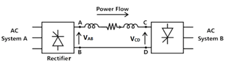
Sign in to UnlockPower is transferred from system A to system B by an HVDC link as shown in the figure. If the voltages and are as indicated in the figure and l > 0, then


Sign in to see the solution
Log in to view the explanation, track your attempts, and keep your progress.
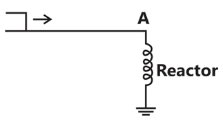
Sign in to UnlockConsider a step voltage wave of magnitude 1pu travelling along a lossless transmission line that terminates in a reactor. The voltage magnitude across the reactor at the instant the travelling wave reaches the reactor is
Sign in to see the solution
Log in to view the explanation, track your attempts, and keep your progress.
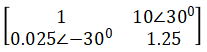
Sign in to UnlockConsider two buses connected by an impedance of. The bus 1 voltage is 10030°V, and bus 2 voltage is . The real and reactive power supplied by bus 1, respectively are


Sign in to see the solution
Log in to view the explanation, track your attempts, and keep your progress.
Sign in to UnlockA 50Hz synchronous generator is initially connected to a long lossless transmission line which is open circuited at the receiving end. With the field voltage held constant, the generator is disconnected from the transmission line. Which of the following may be said about the steady state terminal voltage and field current of the generator?

Sign in to see the solution
Log in to view the explanation, track your attempts, and keep your progress.
Sign in to UnlockConsider a three-phase, 50Hz, 11kV distribution system. Each of the conductors is suspended by an insulator string having two identical porcelain insulators. The self capacitance of the insulator is 5 times, the shunt capacitance between the link and the ground, as shown in the figure. The voltages across the two insulators are
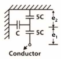


Sign in to see the solution
Log in to view the explanation, track your attempts, and keep your progress.
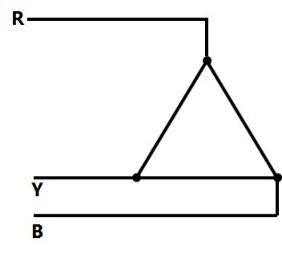
Sign in to UnlockConsider a three-core, three-phase, 50Hz, 11kV cable whose conductors are denoted as R,Y, and B in the figure. The inter-phase capacitance () between each pair of conductors is and the capacitance between each line conductor and the sheath is. The per-phase charging current is


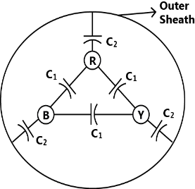
Sign in to see the solution
Log in to view the explanation, track your attempts, and keep your progress.
Sign in to UnlockFor a fixed value of complex power flow in a transmission line having a sending end voltage V, the real power loss will be proportional to
V


Sign in to see the solution
Log in to view the explanation, track your attempts, and keep your progress.
Sign in to UnlockMatch the items in List-I with the items in List-II and select the correct answer using the codes given below the lists.
List I | List II |
To | Use |
a. Improve power factor | 1. shunt reactor |
b. Reduce the current ripples | 2. shunt capacitor |
c. Increase the power flow in line | 3. series capacitor |
d. Reduce the Ferranti effect | 4. series reactor |
Sign in to see the solution
Log in to view the explanation, track your attempts, and keep your progress.
Sign in to UnlockThree generators are feeding a load of 100 MW. The details of the generators are
Rating (MW) | Efficiency (%) | Regulation (p.u.) on 100 MAVA base | |
Generator-1 | 100 | 20 | 0.02 |
Generator-2 | 100 | 30 | 0.04 |
Generator-3 | 100 | 40 | 0.03 |
In the event of increased load power demand, which of the following will happen?
Sign in to see the solution
Log in to view the explanation, track your attempts, and keep your progress.
Sign in to UnlockAn extra high voltage transmission line of length 300 km can be approximated by a lossless line having propagation constant β=0.00127 radians per km. Then the percentage ratio of line length to wavelength will be given by
Sign in to see the solution
Log in to view the explanation, track your attempts, and keep your progress.
Sign in to UnlockA lossless transmission line having Surge Impedance Loading (SIL) of 2280 MW is provided with a uniformly distributed series capacitive compensation of 30%. Then, SIL of the compensated transmission line will be
Sign in to see the solution
Log in to view the explanation, track your attempts, and keep your progress.
Sign in to UnlockSingle line diagram of a 4-bus single source distribution system is shown below. Branches and have equal impedances. The load current values indicated in the figure are in per unit.


Distribution Company’s policy requires radial system operation with minimum loss, this can be achieved by opening of the branch


Sign in to see the solution
Log in to view the explanation, track your attempts, and keep your progress.
Sign in to UnlockConsider the transformer connections in a part of a power system shown in the figure. The nature of transformer connections and phase shifts are indicated for all but one transformer. Which of the following connections, and the corresponding phase shift , should be used for the transformer between A and B?

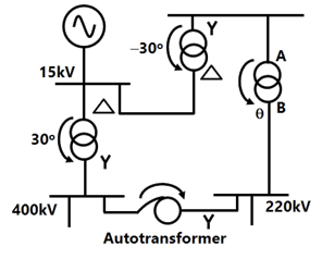


Sign in to see the solution
Log in to view the explanation, track your attempts, and keep your progress.
Sign in to UnlockTwo regional systems, each having several synchronous generators and loads are interconnected by an ac line and a HVDC link as shown in the figure. Which of the following statements is true in the steady state:
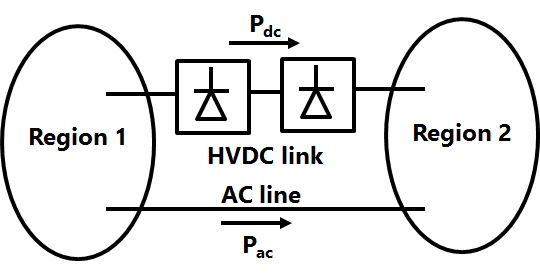
Both regions need not have the same frequency.
The total power now between the regions can be changed by controlling the HVDC converters alone.

The power sharing between the ac line and the HVDC link can be changed by controlling the HVDC converters alone.
The direction of power now in the HVDC link cannot be reversed.

Sign in to see the solution
Log in to view the explanation, track your attempts, and keep your progress.
Sign in to UnlockConsider a bundled conductor of an overhead line, consisting of three identical sub-conductors placed at the corners of an equilateral triangle as shown in the figure. If we neglect the charges on the other phase conductors and ground, and assume that spacing between sub-conductors is much larger than their radius, the maximum electric field intensity is experienced at
Sign in to see the solution
Log in to view the explanation, track your attempts, and keep your progress.
Sign in to UnlockThe total reactance and total susceptance of a lossless overhead EHV line, operating at 50 Hz. are given by 0.045pu and 1.2pu respectively. If the velocity of wave propagation is , then the approximate length of the line is

Sign in to see the solution
Log in to view the explanation, track your attempts, and keep your progress.
Sign in to UnlockConsider the two power systems shown in figure A below, which are initially not interconnected, and are operating in steady state at the same frequency. Separate load flow solutions are computed individually for the two systems, corresponding to this scenario. The bus voltage phasors so obtained are indicated on figure A. These two isolated systems are now interconnected by a short transmission line as shown in figure B, and it is found that.

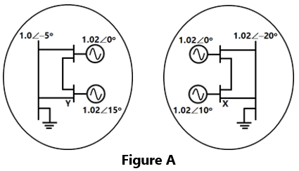
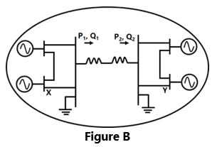
The bus voltage phase angular difference between generator bus X and generator bus Y after the interconnection is


Sign in to see the solution
Log in to view the explanation, track your attempts, and keep your progress.
Sign in to UnlockA 230 V (Phase). 50 Hz, three-phase, 4-wire system has a phase sequence ABC. A unity power-factor load of 4 kW is connected between phase A and neutral N. It is desired to achieve zero neutral current through the use of a pure inductor and a pure capacitor in the other two phases. The value of inductor and capacitor is
Sign in to see the solution
Log in to view the explanation, track your attempts, and keep your progress.
Sign in to UnlockThe concept of an electrically short, medium and long line is primarily based on the
Sign in to see the solution
Log in to view the explanation, track your attempts, and keep your progress.
Sign in to UnlockAn HVDC link consists of rectifier, inverter transmission line and other equipment’s. Which one of the following is true for this link?
Sign in to see the solution
Log in to view the explanation, track your attempts, and keep your progress.
Sign in to UnlockA 400V, 50 Hz, three phase balanced source supplies power to a star connected load whose rating is kVA, 0.8 pf (lag). The rating (in kVAR) of the delta connected (capacitive) reactive power bank necessary to bring the pf to unity is

Sign in to see the solution
Log in to view the explanation, track your attempts, and keep your progress.
Sign in to UnlockThe A, B, C, D constants of a 220 kV line are: , , . If the sending end voltage of the line for a given load delivered at nominal voltage is 240 kV, then % voltage regulation of the line is


Sign in to see the solution
Log in to view the explanation, track your attempts, and keep your progress.
Sign in to UnlockA single phase transmission line and a telephone line are both symmetrically strung one below the other, in horizontal configurations, on a common tower. The shortest and longest distances between the phase and telephone conductors are 2.5 m and 3 m respectively. The voltage (volt/km) inducted in the telephone circuit, due to 50 Hz current of 100 amps in the power circuit is
Sign in to see the solution
Log in to view the explanation, track your attempts, and keep your progress.
Sign in to UnlockAn 800 kV transmission line has a maximum power transfer capacity P, on the operated at 400 kV with the series reactance unchanged, the new maximum power transfer capacity is approximately
P
2P


Sign in to see the solution
Log in to view the explanation, track your attempts, and keep your progress.
Sign in to UnlockThe insulation strength of an EHV transmission line is mainly governed by
Sign in to see the solution
Log in to view the explanation, track your attempts, and keep your progress.
Sign in to UnlockHigh Voltage DC (HVDC) transmission is mainly used for
Sign in to see the solution
Log in to view the explanation, track your attempts, and keep your progress.
Sign in to UnlockAt an industrial sub-station with a 4 MW load, a capacitor of 2 MVAR is installed to maintain the load power factor at 0.97 lagging. If the capacitor goes out of service, the load power factor becomes
Sign in to see the solution
Log in to view the explanation, track your attempts, and keep your progress.
Sign in to UnlockThe rated voltage of a 3-phase power system is given as
Sign in to see the solution
Log in to view the explanation, track your attempts, and keep your progress.
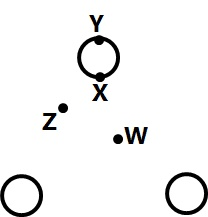
Sign in to UnlockThe phase sequence of the 3-phase system shown in Figure is
Sign in to see the solution
Log in to view the explanation, track your attempts, and keep your progress.
Sign in to UnlockAn 800 kV transmission line is having per phase line inductance of 1.1mH/km and per phase line capacitance of 11.68nF/km. Ignoring the length of the line, its ideal power transfer capability in MW is
Sign in to see the solution
Log in to view the explanation, track your attempts, and keep your progress.
Sign in to UnlockA 110 kV, single core coaxial, XLPE insulated power cable delivering power at 50 Hz, has a capacitance of 125nF/km. If the dielectric loss tangent of XLPE is , the dielectric power loss in this cable in W/km is

Sign in to see the solution
Log in to view the explanation, track your attempts, and keep your progress.
Sign in to UnlockA lightning stroke discharges impulse current of 10 kA (peak) on a 400 kV transmission line having surge impedance of 250Ω. The magnitude of transient over-voltage traveling waves in either direction assuming equal distribution form the point of lightning strike will be
Sign in to see the solution
Log in to view the explanation, track your attempts, and keep your progress.
Sign in to UnlockThe generalized circuit constants of a 3-phase, 220 kV rated voltage, medium length transmission line are


If the load at the receiving end is 50 MW at 220 kV with a power factor of 0.9 lagging, the magnitude of line to line sending end voltage should be
Sign in to see the solution
Log in to view the explanation, track your attempts, and keep your progress.
Sign in to UnlockA new generator having [equivalent to (1.212+j0.70) p.u. and synchronous reactanceof 1.0 p.u. on the system base, is to be connected to a bus having voltage in the existing power system. This existing power system can be represented by Thevenin’s voltage in series with Thevenin’s impedance . The magnitude of the bus voltage of the system in pu will be


Sign in to see the solution
Log in to view the explanation, track your attempts, and keep your progress.
Sign in to UnlockBundled conductors are mainly used in high voltage overhead transmission lines to
Sign in to see the solution
Log in to view the explanation, track your attempts, and keep your progress.
Sign in to UnlockChoose two appropriate auxiliary components of a HVDC transmission system from the following
P. D.C. line inductor
Q. A.C. line inductor
R. Reactive power sources
S. Distance relays on D.C. line
T. Series capacitance of A.C. line
Sign in to see the solution
Log in to view the explanation, track your attempts, and keep your progress.
Sign in to UnlockA balanced delta connected load of (8+j6) Ω per phase is connected to a 400 V, 50 Hz, 3-phase supply lines. If the input power factor is to be improved to 0.9 by connecting a bank of star connected capacitors the required kVAR of the bank
Sign in to see the solution
Log in to view the explanation, track your attempts, and keep your progress.
Sign in to UnlockThe ABCD parameters of a 3-phase overhead transmission line are , and . At no-load condition a shunt inductive reactor is connected at the receiving end of the line to limit the receiving end voltage to be equal to the sending end voltage. The ohmic value of the reactor is


Sign in to see the solution
Log in to view the explanation, track your attempts, and keep your progress.
Sign in to UnlockA surge of 20 kV magnitude travels along a lossless cable towards its junction with two identical lossless overhead transmission lines. The inductance and the capacitance of the cable are 0.4mH and 0.5µF per km. The inductance and capacitance of the overhead transmission lines are 1.5mH and 0.015µF per km. The magnitude of the voltage at the junction due to surge is
Sign in to see the solution
Log in to view the explanation, track your attempts, and keep your progress.
Sign in to UnlockA dc distribution system is shown in Figure with load currents as marked. The two ends of the feeder are fed by voltage sources such that, the value of the voltage for a minimum voltage of 220V at any point along the feeder is


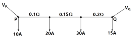
Sign in to see the solution
Log in to view the explanation, track your attempts, and keep your progress.
Sign in to UnlockA 3-phase, 11-kV generator feeds power to a constant power unity power factor load of 100 MW through a 3-phase transmission line. The line-to-line voltage at the terminals of the machine is maintained constant at 11 kV. The per unit positive sequence impedance of the line based on 100 MVA and 11 kV is j 0.2. The line-to-line voltage at the load terminals is measured to be less than 11 kV. The total reactive power to be injected at the terminals of the load to increase the line-to-line voltage at the load terminals to 11 kV is
Sign in to see the solution
Log in to view the explanation, track your attempts, and keep your progress.
Sign in to UnlockConsider a long, two-wire line composed of solid round conductors. The radius of both conductors is 0.25 cm and the distance between their centers is 1m. If this distance is doubled, then the inductance per unit length
Sign in to see the solution
Log in to view the explanation, track your attempts, and keep your progress.
Sign in to UnlockConsider a power system with three identical generators. The transmission losses are negligible. One generator () has a speed governor which maintains its speed constant at the rated value, while the other generators (and ) have governors with a drop of 5%.If the load of the system is increased, then in steady state.


Generation of and is increased equally while generation of is unchanged.
Generation of alone is increased while generation of and is unchanged.
Generation of , and is increased equally.
Generation of , and is increased in the ratio 0.5:0.25:0.25.
Sign in to see the solution
Log in to view the explanation, track your attempts, and keep your progress.
Sign in to UnlockA long wire composed of a smooth round conductor runs above and parallel to the ground (assumed to be a large conducting plane). A high voltage exists between the conductor and the ground. The maximum electric stress occurs at
Sign in to see the solution
Log in to view the explanation, track your attempts, and keep your progress.
Sign in to UnlockA transmission line has a total series reactance of 0.2 pu. Reactive power compensation is applied at the midpoint of the line and it is controlled such that the midpoint voltage of the transmission line is always maintained at 0.98 pu. If voltage at both ends of the line are maintained at 1.0 pu, then the steady state power transfer limit of the transmission line is
Sign in to see the solution
Log in to view the explanation, track your attempts, and keep your progress.
Sign in to UnlockA long lossless transmission line has a unity power factor (UPF) load at the receiving end and an ac voltage source at the sending end (Figure). The parameters of the transmission line are as follows:
Characteristic impedance , propagation constant , and length. The equation relating sending and receiving end questions is


Compute the maximum power that can be transferred to the UPF load at the receiving end if .


Sign in to see the solution
Log in to view the explanation, track your attempts, and keep your progress.
Sign in to UnlockA 50 Hz balanced three-phase, Y-connected supply is connected to a balanced three phase Y-connected load. If the instantaneous phase-α of the supply voltage is and the phase-α of the load current is , the instantaneous three-phase power is


A constant with a magnitude of

A constant with a magnitude of

Time-varying with an average value of and a frequency of 100Hz
Time-varying with an average value of and a frequency of 50 Hz

Sign in to see the solution
Log in to view the explanation, track your attempts, and keep your progress.
Sign in to UnlockA lossless radial transmission line with surge impedance loading
Sign in to see the solution
Log in to view the explanation, track your attempts, and keep your progress.
Sign in to UnlockConsider the model shown in Figure of a transmission line with a series capacitor at its mid-point. The maximum voltage on the line is at the location


Sign in to see the solution
Log in to view the explanation, track your attempts, and keep your progress.
Sign in to UnlockA power system has two synchronous generators. The Governor-turbine characteristics corresponding to the generators are. Where f denotes the system frequency in Hz, and and are, respectively, the power outputs (in MW) of turbines 1 and 2 assuming the generators and transmission network to be lossless, the system frequency for a total load of 400 MW is

Sign in to see the solution
Log in to view the explanation, track your attempts, and keep your progress.
Sign in to UnlockThe conductors of a 10 km long, single phase, two wire line are separated by a distance of 1.5m. The diameter of each conductor is 1 cm. If the conductors are of copper, the inductance of the circuit is
Sign in to see the solution
Log in to view the explanation, track your attempts, and keep your progress.
Sign in to UnlockA 132 kV transmission line AB is connected to a cable BC. The characteristic impedances of the overhead line and the cable are 400Ω and 80Ω respectively. Assume that these are purely resistive. A 250 kV switching surge travels from A to B.
(a) Calculate the value of this voltage surge when it first reaches C.
(b) Calculate the value of the reflected component of this surge when the first reflection reaches A.
(c) Calculate the surge current in the cable BC.
Sign in to see the solution
Log in to view the explanation, track your attempts, and keep your progress.
Sign in to UnlockOut of the considerations (i) and (iv) listed below
(i) No distance limitation related to steady state stability
(ii) No reactive power requirement from the system at the two terminals
(iii) No substantial effect fault level of the two systems at the terminals in spite of the interconnection
(iv) No corona problems
The considerations, which constitute advantage of HVDC transmission, are
Sign in to see the solution
Log in to view the explanation, track your attempts, and keep your progress.
Sign in to UnlockThe corona loss on a particular system at 50 Hz is 1kW/km per phase. The corona loss at 60 Hz would be
Sign in to see the solution
Log in to view the explanation, track your attempts, and keep your progress.
Sign in to UnlockA 275kV, 3-phase, 50 Hz, 400km lossless line has following parameters:
, line charging susceptance micro-Siemens/km


(a) Calculate the receiving end voltage on open circuit using justifiable assumptions.
(b) What load at the receiving end will result in a flat voltage profile on the line?
(c) If the flat voltage profile is to be achieved at 1.2 times the loading in (b), what will be the nature and quantum of uniformly distributed compensation required
Sign in to see the solution
Log in to view the explanation, track your attempts, and keep your progress.
Sign in to UnlockAn overhead line having a surge impedance of 400Ω is connected in series with an underground cable having a surge impedance of 100Ω. If a surge of 50kV travels from the line end towards the line-cable junctions, the value of the transmitted voltage wave at the junction is:
Sign in to see the solution
Log in to view the explanation, track your attempts, and keep your progress.
Sign in to UnlockThe load carrying capability of a long AC transmission line is:
Sign in to see the solution
Log in to view the explanation, track your attempts, and keep your progress.
Sign in to UnlockCorona losses are minimized when
Sign in to see the solution
Log in to view the explanation, track your attempts, and keep your progress.
Sign in to UnlockIn a DC transmission line
Sign in to see the solution
Log in to view the explanation, track your attempts, and keep your progress.
Sign in to UnlockFor a single phase overhead line having solid copper conductors of diameter 1cm, spaced 60cm between centers, the inductance in mH/km is:


Sign in to see the solution
Log in to view the explanation, track your attempts, and keep your progress.
Sign in to UnlockA single phase AC distributor supplies two single phase loads as shown in fig. The voltage drop from A to C is:
Sign in to see the solution
Log in to view the explanation, track your attempts, and keep your progress.
Sign in to UnlockA 220kV, 20 km long , 3-phase transmission line has the following A, B, C, D constants. , ,


11A
220A

Sign in to see the solution
Log in to view the explanation, track your attempts, and keep your progress.
Sign in to UnlockA 3-phase, 11kV, 50 Hz, 200 kW load has a power factor of 0.8lag. A delta connected 3-phase capacitor is used to improve the power factor to unity. The capacitance power phase of the capacitor in microfarads is
Sign in to see the solution
Log in to view the explanation, track your attempts, and keep your progress.
Sign in to UnlockA 6.6kV, 50Hz, single core lead-sheathed cable has the following data:
Conductor diameter: 1.5cm, length: 4km
Internal diameter of the sheath: 3cm
Resistivity of insulation:

Relative permittivity of insulation: 3.5
Calculate:
(a) The insulation resistance
(b) The capacitance and
(c) The maximum electric stress in the insulation
Sign in to see the solution
Log in to view the explanation, track your attempts, and keep your progress.
Sign in to UnlockA 66 kV, 3-phase, 50Hz, 150km long overhead transmission line is open circuited at the receiving end. Each conductor has a resistance of 0.25 Ω/km, an inductive reactance of 0.5 Ω/km and a capacitive admittance to neutral of

Draw the nominal π-equivalent circuit and Calculate the receiving end voltage (kV) if the sending end voltage is 66kV
Sign in to see the solution
Log in to view the explanation, track your attempts, and keep your progress.
Sign in to UnlockIn a transmission line each conductor is at 20 kV and is supported by a string of 3 suspension insulators. The air capacitance between each cap-pin junction and tower is one-fifth of the capacitance C of each insulator unit. A guard ring, effective only over the line-end insulator unit is fitted so that the voltages on the two units nearest the line-end are equal
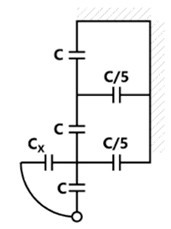
(a) Calculate the voltage on the line-end unit
(b) Calculate the value of capacitance required

Sign in to see the solution
Log in to view the explanation, track your attempts, and keep your progress.
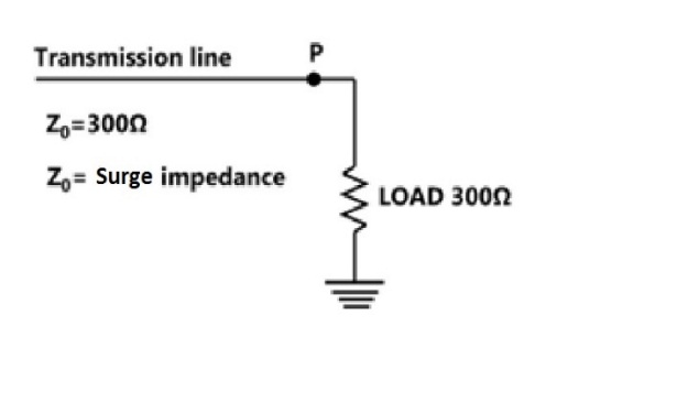
Sign in to UnlockThe reflection coefficient for the transmission line shown in fig. at P is:
Sign in to see the solution
Log in to view the explanation, track your attempts, and keep your progress.
Sign in to UnlockSeries capacitive compensation in EHV transmission lines is used to
Sign in to see the solution
Log in to view the explanation, track your attempts, and keep your progress.
Sign in to UnlockBulk power transmission over long HVDC lines is preferred, on account of
Sign in to see the solution
Log in to view the explanation, track your attempts, and keep your progress.
Sign in to UnlockIf the length of a wire of resistance R is uniformly stretched to n times its original value, its new resistance is
nR


Sign in to see the solution
Log in to view the explanation, track your attempts, and keep your progress.
Sign in to UnlockA cable has the following characteristics. .

The velocity of wave propagation through the cable is:
Sign in to see the solution
Log in to view the explanation, track your attempts, and keep your progress.
Sign in to UnlockA shunt reactor of 100MVAr is operated at 98% of its rated voltage and at 96% of its rated frequency. The reactive power absorbed by the reactor is:
Sign in to see the solution
Log in to view the explanation, track your attempts, and keep your progress.
Sign in to UnlockEach conductor of a 33KV, 3-phase system is suspended by a string of three similar insulars. The ratio of shunt capacitance to mutual capacitance is 0.1. Calculate the voltage across each insulator, and the string efficiency.
Sign in to see the solution
Log in to view the explanation, track your attempts, and keep your progress.
Sign in to UnlockA circuit consisting of a single resistor R and an inductor L in series is driven by a 25V RMS, 50 Hz sinusoidal voltage source. A capacitor is to be placed in parallel with the source to improve the power factor. Given that the average power dissipated in the R is 100W and that the reactive power delivered to the L is 75VAR, what value of C will yield a 0.9 p.f. lagging as seen by the source?
Sign in to see the solution
Log in to view the explanation, track your attempts, and keep your progress.
Sign in to UnlockBundled conductors are employed to improve the
Sign in to see the solution
Log in to view the explanation, track your attempts, and keep your progress.
Sign in to UnlockThe velocity of propagation of electromagnetic wave on an underground cable with relative permittivity of 3 will be __________
Sign in to see the solution
Log in to view the explanation, track your attempts, and keep your progress.
Sign in to UnlockTwo power systems A and B each having a regulation (R) of 0.05 p.u. on their respectively capacity bases and a stiffness (damping coefficient) of 0.75 p.u. are connected through a tie-line, initially carrying no power. The capacity of system A is 2000 MW and that of system B is 3000MW. If there is an increase in load of 200MW in system A, what is the change in the steady-state frequency and power transfer?
Sign in to see the solution
Log in to view the explanation, track your attempts, and keep your progress.
Sign in to UnlockA factory draws 100kW at 0.7p.f lagging from a 3-phase, 11 kV supply. It is desired to raise the p.f. to 0.95 lagging using series capacitors. Calculate the rating of the capacitor required in μF .
Sign in to see the solution
Log in to view the explanation, track your attempts, and keep your progress.
Sign in to UnlockFor a 500Hz frequency excitation, a 50km long power line will be modeled as
Sign in to see the solution
Log in to view the explanation, track your attempts, and keep your progress.
Sign in to UnlockFor equilateral spacing of conductors of an untransposed 3-phase line, we have
Sign in to see the solution
Log in to view the explanation, track your attempts, and keep your progress.
Sign in to UnlockThe per unit voltages of two synchronous machines connected through a lossless line are. Match the two sides in the following

(a) Real power of machine 1 | (P) Positive real power |
(b) Reactive power of machine 1 | (Q) Positive reactive power |
(c) Power factor of machine 1 | (R) Negative real power |
(S) Negative reactive power | |
(T) Leading power factor | |
(U) Lagging power factor |
Sign in to see the solution
Log in to view the explanation, track your attempts, and keep your progress.
Sign in to UnlockThe surge impedance of a 400 km long overhead transmission line is 400 ohms. For a 200 km length of the same line, the surge impedance will be:
Sign in to see the solution
Log in to view the explanation, track your attempts, and keep your progress.
Sign in to UnlockThe insulation level of a 400 kV EHV overhead transmission line is decided on the basis of
Sign in to see the solution
Log in to view the explanation, track your attempts, and keep your progress.
Sign in to UnlockThe main criterion for selection of the size of a distribution for a radial distribution system is:
Sign in to see the solution
Log in to view the explanation, track your attempts, and keep your progress.
Sign in to UnlockThe insulation resistance of a cable of length 10 km is 1 MΩ. For a length of 100 km of the same cable, the insulation resistance will be
Sign in to see the solution
Log in to view the explanation, track your attempts, and keep your progress.
Sign in to UnlockThe rated load of an underground cable is always greater than its natural load. (True=1/False=0)
Sign in to see the solution
Log in to view the explanation, track your attempts, and keep your progress.
Sign in to UnlockTwo identical three-phase transmission lines are connected in parallel to supply a total load of 100 MW at 132 kV and 0.8p.f lagging at the receiving end. The ABCD constants of each transmission line are as follows:
;


Determine:
(a) The ABCD constants of the combined network.
(b) The sending-end power factor
(a)
(b) 0.729
(a)
(b) 0.829
(a)
(b) 0.629
(a)
(b) 0.729
Sign in to see the solution
Log in to view the explanation, track your attempts, and keep your progress.
Sign in to UnlockIn a string of three identical suspension insulator units supporting a transmission line conductor, if the self capacitance of each unit is denoted as C Farads, the capacitance of each connector pin to ground can be taken as 0.1 C Farads. Determine the voltage distribution across the string if the maximum permissible voltage per unit is given as 20kV. Also determine the string efficiency.
Sign in to see the solution
Log in to view the explanation, track your attempts, and keep your progress.
Sign in to UnlockIn a 400 kV network, 360 kV is recorded at a 400 kV bus. The reactive power absorbed by a shunt rated for 50 MVAR, 400 kV connected at the bus is
Sign in to see the solution
Log in to view the explanation, track your attempts, and keep your progress.
Sign in to UnlockHVDC Transmission is preferred to EHV-AC because
Sign in to see the solution
Log in to view the explanation, track your attempts, and keep your progress.
Sign in to UnlockThe charging current of a 400kV transmission line is more than that of a 220kV line of the same length. (True=1/False=0)
Sign in to see the solution
Log in to view the explanation, track your attempts, and keep your progress.
Sign in to UnlockThe increase in resistance due to non-uniform distribution of current in a conductor is known as skin effect. (True=1/False=0)
Sign in to see the solution
Log in to view the explanation, track your attempts, and keep your progress.
Sign in to UnlockA three-phase overhead transmission line has its conductors horizontally spaced with spacing between adjacent conductors equal to ‘d’. If now the conductors of the line are rearranged to form an equilateral triangle of sides equal to ‘d’ then :
Sign in to see the solution
Log in to view the explanation, track your attempts, and keep your progress.
Sign in to UnlockThe inductance of a power transmission line increases with
Sign in to see the solution
Log in to view the explanation, track your attempts, and keep your progress.
Sign in to UnlockThe selection of size of conductors for a distributor in a distribution system is governed by
Sign in to see the solution
Log in to view the explanation, track your attempts, and keep your progress.
Sign in to UnlockWhen a fixed amount of power is to be transmitted, the efficiency of transmission increases when
Sign in to see the solution
Log in to view the explanation, track your attempts, and keep your progress.
Sign in to UnlockRing main distribution system is preferred to a radial system, because
Sign in to see the solution
Log in to view the explanation, track your attempts, and keep your progress.
Sign in to UnlockThe mica layer in a parallel plate capacitor with an effective area of 120 has a damaged section equivalent to a hole of 0.5 mm diameter. Which of the following would be significantly affected by the damage?


Capacitance
Charge
Dielectric breakdown strength

Sign in to see the solution
Log in to view the explanation, track your attempts, and keep your progress.
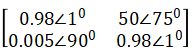
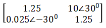
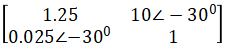
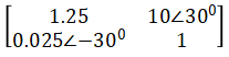
Sign in to UnlockTwo transmission lines are connected in cascade, whose ABCD parameters are

Respectively. Find the resultant ABCD parameters.
Sign in to see the solution
Log in to view the explanation, track your attempts, and keep your progress.
Sign in to Unlock