Network Analysis
Network Theorems (DC Circuits)
Practice questions from Network Theorems (DC Circuits).
27
Total0
Attempted0
Correct0
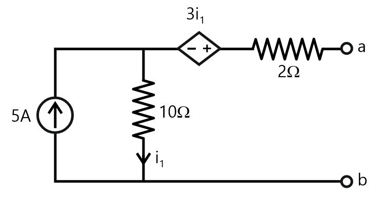
IncorrectFor the network shown, the equivalent Thevenin voltage and Thevenin impedance as seen across terminals 'ab' is
Explanation Locked!
Unlock this branch to view the explanation, track, bookmark and more.
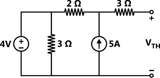
Sign in to UnlockThe Thevenin equivalent voltage, , in V (rounded off to 2 decimal places) of the network shown below, is

Explanation Locked!
Unlock this branch to view the explanation, track, bookmark and more.
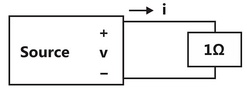
Sign in to UnlockA benchtop DC power supply acts as an ideal 4 A current source as long as its terminal voltage is below 10 V. Beyond this point, it begins to behave as an ideal 10 V voltage source for all load currents going down to 0A. When connected to an ideal rheostat, find the load resistance value at which maximum power is transferred, and the corresponding load voltage and current.
Explanation Locked!
Unlock this branch to view the explanation, track, bookmark and more.
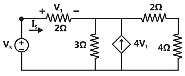
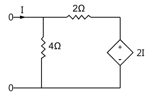
Sign in to UnlockThe driving point input impedance seen from the source of the circuit shown below, in is ___________.


Explanation Locked!
Unlock this branch to view the explanation, track, bookmark and more.
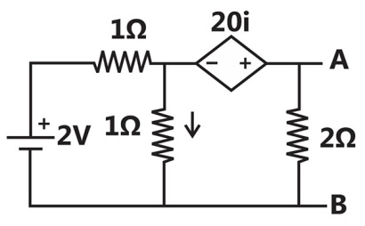
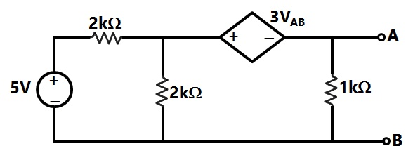
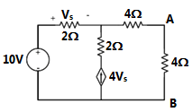
Sign in to UnlockFor the given circuit, the Thevenin equivalent is to be determined. The Thevenin voltage,

(in Volt), seen from terminal AB is _____________.
Explanation Locked!
Unlock this branch to view the explanation, track, bookmark and more.
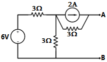
Sign in to UnlockThe current i(in Ampere) in the resistor of the given network is _______.

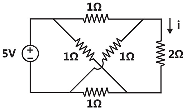
Explanation Locked!
Unlock this branch to view the explanation, track, bookmark and more.
Sign in to UnlockA non-ideal voltage source has an internal impedance of . If a purely resistive load is to be chosen that maximizes the power transferred to the load, its value must be


0
real part of
magnitude of
complex conjugate of
Explanation Locked!
Unlock this branch to view the explanation, track, bookmark and more.
Sign in to UnlockThe Norton’s equivalent source in amperes as seen into the terminals X and Y is__________.
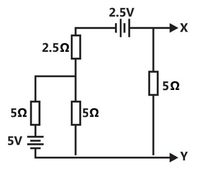
Explanation Locked!
Unlock this branch to view the explanation, track, bookmark and more.
Sign in to UnlockA source has an internal impedance of . If a purely resistive load connected to this source has to extract the maximum power out of the source, its value in Ω should beA source has an internal impedance of . If a purely resistive load connected to this source has to extract the maximum power out of the source, its value in Ω should be


Explanation Locked!
Unlock this branch to view the explanation, track, bookmark and more.
Sign in to UnlockThe impedance looking into nodes 1 and 2 in the given circuit is
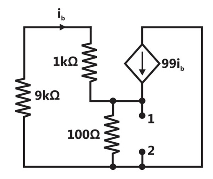


Explanation Locked!
Unlock this branch to view the explanation, track, bookmark and more.
Sign in to UnlockWith 10V dc connected at port A in the linear nonreciprocal two-port network shown below, the following were observed:
(i) connected at port B draws a current of 3A

(ii) connected at port B draws a current of 2A

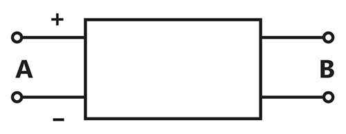
For the same network, with 6V dc connected at port A, connected at port B draws 7/3A. If 8V dc connected to port A, the open circuit voltage at port B is
Explanation Locked!
Unlock this branch to view the explanation, track, bookmark and more.
Sign in to UnlockWith 10V dc connected at port A in the linear nonreciprocal two-port network shown below, the following were observed:
(i) connected at port B draws a current of 3A
(ii) connected at port B draws a current of 2A
With 10V dc connected at port A, the current drawn by connected at port B is

Explanation Locked!
Unlock this branch to view the explanation, track, bookmark and more.
Sign in to UnlockIn the circuit given below, the value of R required for the transfer of maximum power to the load having a resistance of is

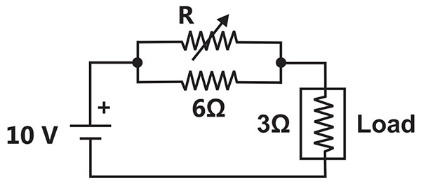
Zero

Infinity
Explanation Locked!
Unlock this branch to view the explanation, track, bookmark and more.
Sign in to UnlockAs shown in the figure, a resistance is connected across a source that has a load line
v + i = 100. The current through the resistance is
Explanation Locked!
Unlock this branch to view the explanation, track, bookmark and more.
Sign in to UnlockFor the circuit shown, find out the current flowing through the 2Ω resistance. Also identify the changes to be made to double the current through the 2Ω resistance.
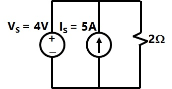
(5A; Put = 20V)
(2A; Put = 8V)
(5A; Put = 10V)
(7A; Put = 12V)
Explanation Locked!
Unlock this branch to view the explanation, track, bookmark and more.
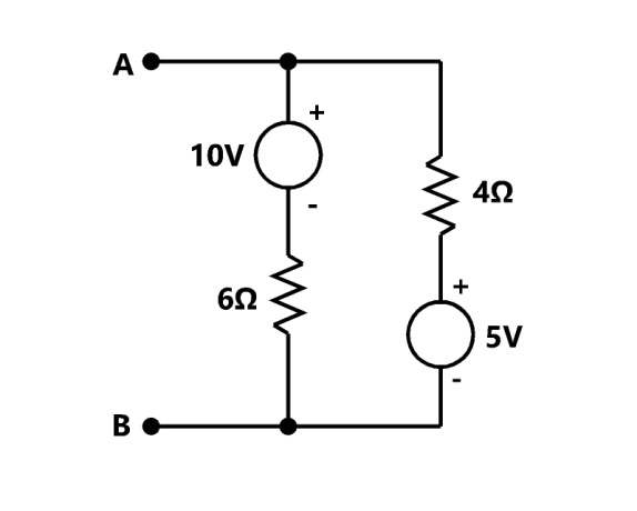
Sign in to UnlockFor the circuit given, the Thevenin's resistance across the terminals A and B is
Explanation Locked!
Unlock this branch to view the explanation, track, bookmark and more.
Sign in to UnlockFor the circuit given, the Thevenin's voltage across the terminals A and B is
Explanation Locked!
Unlock this branch to view the explanation, track, bookmark and more.
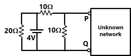
Sign in to UnlockIn Figure, the Thevenin’s equivalent pair (voltage, impedance), as seen at the terminals P-Q, is given by
Explanation Locked!
Unlock this branch to view the explanation, track, bookmark and more.
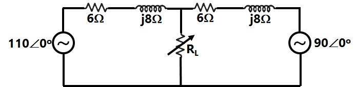
Sign in to UnlockTwo ac sources feed a common variable resistive load as shown in Figure. Under the maximum power transfer condition, the power absorbed by the load resistance RL is
Explanation Locked!
Unlock this branch to view the explanation, track, bookmark and more.
Sign in to UnlockThe circuit shown in figure is equivalent to a load of


4 ohms
2 ohms
Explanation Locked!
Unlock this branch to view the explanation, track, bookmark and more.
Sign in to UnlockViewed from the terminals A, B the following circuit shown in figure can be reduced to an equivalent circuit of a single voltage source series with a single resistance with the following parameters:
Explanation Locked!
Unlock this branch to view the explanation, track, bookmark and more.
Sign in to UnlockFor the circuit shown in figure. The Norton equivalent source current value is _________ A and its resistance is _________ Ohms
Explanation Locked!
Unlock this branch to view the explanation, track, bookmark and more.
Sign in to UnlockFind the Thevenin equivalent about AB for the circuit shown in figure
Explanation Locked!
Unlock this branch to view the explanation, track, bookmark and more.
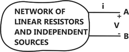
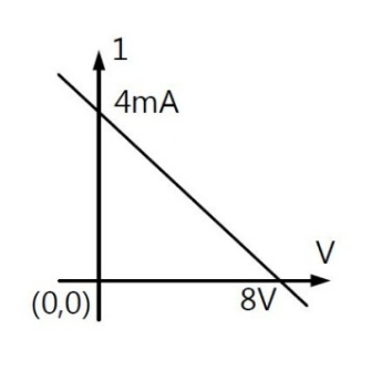
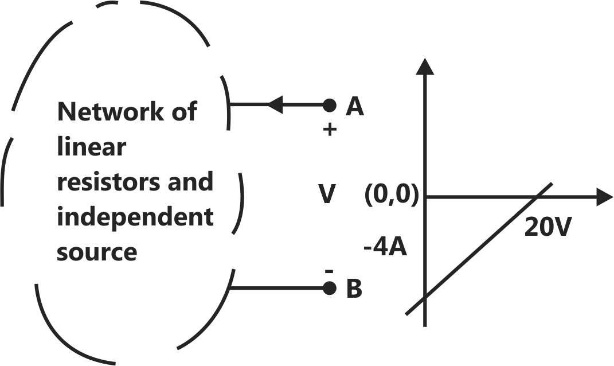
Sign in to UnlockThe V-I characteristic as seen from the terminal- pair (A, B) of the network of figure is shown in figure. If an inductance of value 6mH is connected across the terminal-pair (A, B), the time constant of the system will be


Unknown, unless the actual network is specified
Explanation Locked!
Unlock this branch to view the explanation, track, bookmark and more.
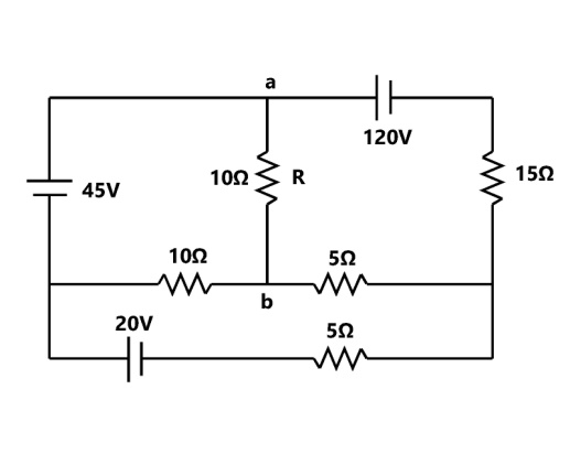
Sign in to UnlockFor the circuit shown in figure, find the current through the resistance R connected between points a and b by Thevenin’s theorem.
Explanation Locked!
Unlock this branch to view the explanation, track, bookmark and more.
Sign in to UnlockThe superposition principle is not applicable to a network containing time-varying resistors
Choose the correct options
Explanation Locked!
Unlock this branch to view the explanation, track, bookmark and more.
Sign in to UnlockThe V-I characteristic as seen from the terminal pair (A,B) of the network of figure (a) is shown figure (b), if a variable resistance is connected across the terminal pair (A,B), the maximum power that can be supplied to would be

Explanation Locked!
Unlock this branch to view the explanation, track, bookmark and more.
Sign in to Unlock