Power Systems
Fault Analysis
Practice questions from Fault Analysis.
67
Total0
Attempted0
Correct0
IncorrectThe initial three-phase voltage phasors (, and ) at a bus of a power network are as shown in Case-1. Due to a disturbance, the bus voltage phasors changed in phase by a small angle , and the magnitudes remained the same as depicted in Case-2.


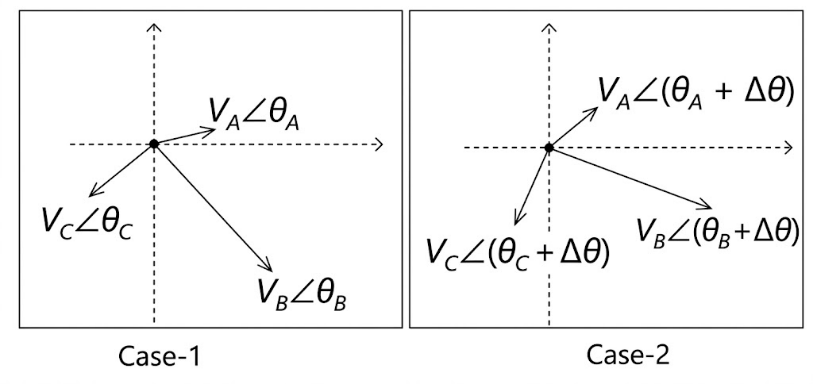
Which one of the following statements is correct about the zero sequence components?
Sign in to see the solution
Log in to view the explanation, track your attempts, and keep your progress.
Sign in to UnlockThe bus impedance matrix of a 3-bus system (in pu) is

A symmetrical fault (through a fault impedance of ) occurs at bus 2. Neglecting pre-fault loading conditions, the voltage at bus 1 , during the fault is __________ pu (round off to three decimal places).

Sign in to see the solution
Log in to view the explanation, track your attempts, and keep your progress.
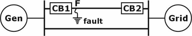
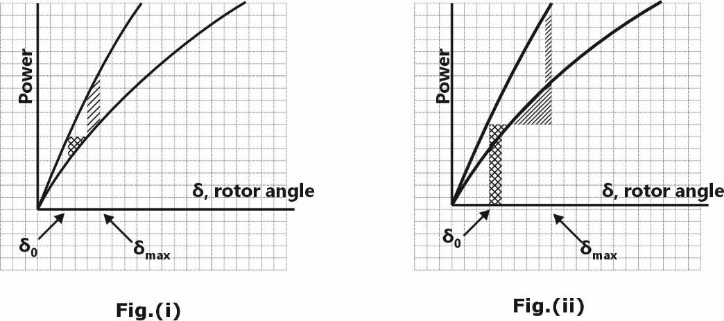
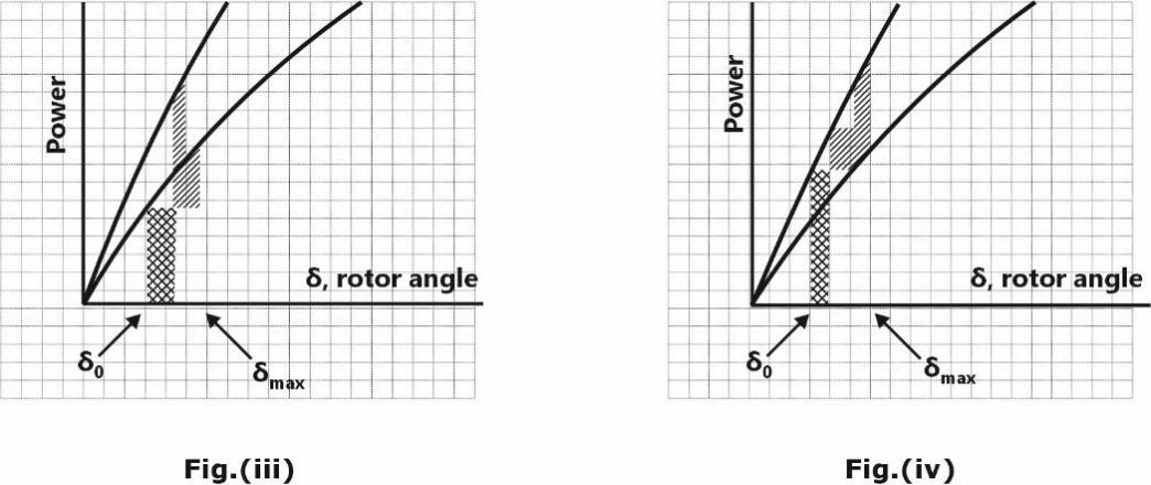
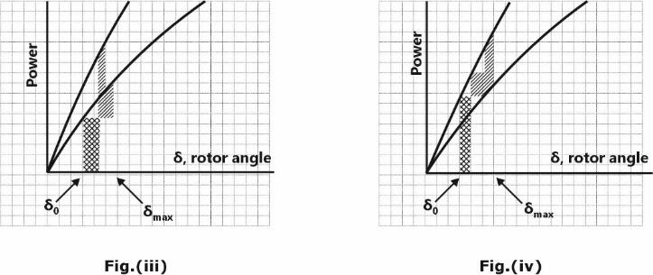
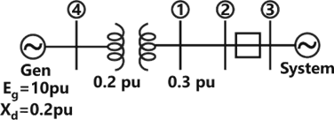
Sign in to UnlockIn the system shown below, the generator was initially supplying power to the grid. A temporary LLLG bolted fault occurs at F very close to circuit breaker 1. The circuit breakers open to isolate the line. The fault self-clears. The circuit breakers reclose and restore the line. Which one of the following diagrams best indicates the rotor accelerating and decelerating areas?
Sign in to see the solution
Log in to view the explanation, track your attempts, and keep your progress.
Sign in to UnlockFor a two-phase network, the phase voltages and are to be expressed in terms of sequence voltages and as . The possible option(s) for matrix S is/are


Sign in to see the solution
Log in to view the explanation, track your attempts, and keep your progress.
Sign in to UnlockThe two-bus power system shown in figure (i) has one alternator supplying a synchronous motor load through a - transformer. The positive, negative and zero-sequence diagrams of the system are shown in figures (ii), (iii) and (iv), respectively. All reactances in the sequence diagrams are in p.u. For a bolted line-to-line fault (fault impedance = zero) between phases ' ' and ' ' at bus 1 , neglecting all pre-fault currents, the magnitude of the fault current (from phase ' ' to ' ') in p.u. is _______ (Round off to 2 decimal places).


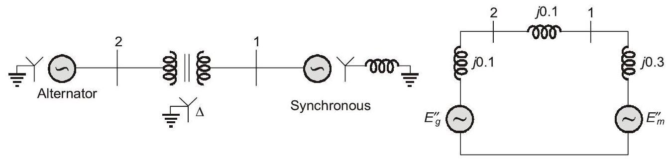
Fig. (i) : Single-line diagram of the power system
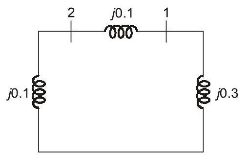
Fig. (iii) : Negative-sequence network Fig. (ii) : Positive-sequence network
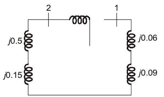
Fig. (iv) : Zero-sequence network
Sign in to see the solution
Log in to view the explanation, track your attempts, and keep your progress.
Sign in to UnlockThe valid positive, negative and zero sequence impedances (in p.u.), respectively, for a 220 kV, fully transposed three-phase transmission line. From the given choices are
(i) 1.1, 0.15 and 0.08
(ii) 0.15, 0.15 and 0.35
(iii) 0.2, 0.2 and 0.2
(iv) 0.1, 0.3 and 0.1
Sign in to see the solution
Log in to view the explanation, track your attempts, and keep your progress.
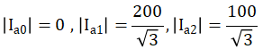
Sign in to UnlockSuppose and are a set of unbalanced current phasors in a three-phase system. The phase-B zero-sequence current If phase-A current and phase-C current , then in p.u is


Sign in to see the solution
Log in to view the explanation, track your attempts, and keep your progress.
Sign in to UnlockFive alternators each rated 5 MVA. 13.2 kV with 25% of reactance on its own base are connected in parallel to a busbar. The short-circuit level in MVA at the busbar is _____________.
Sign in to see the solution
Log in to view the explanation, track your attempts, and keep your progress.
Sign in to UnlockA 30 kV, 50 Hz, 50 MVA generator has the positive, negative, and zero sequence reactances of 0.25 pu, 0.15 pu, and 0.05 pu, respectively. The neutral of the generator is grounded with a reactance so that the fault current for a bolted LG fault and that of a bolted three-phase fault at the generator terminal are equal. The value of grounding reactance in ohms (round off to two decimal place) is ________.
Sign in to see the solution
Log in to view the explanation, track your attempts, and keep your progress.
Sign in to UnlockThe series impedance matrix of a short three-phase transmission line in phase coordinates is

If the positive sequence impedance is and the zero sequence is , then the imaginary part of (in ) is _________(up to 2 decimal places).


Sign in to see the solution
Log in to view the explanation, track your attempts, and keep your progress.
Sign in to UnlockThe positive, negative and zero sequence impedances of a 125 MVA, three-phase, 15.5 kV, star-grounded. 50 Hz generators are j0.1pu, j0.05pu and 10.01pu respectively on the machine rating base. The machine is unloaded and working at the rated terminal voltage. If the grounding impedance of the generator is j0.01pu, then the magnitude of fault current for a b-phase to ground fault (in kA) is _______ (up to 2 decimal places).
Sign in to see the solution
Log in to view the explanation, track your attempts, and keep your progress.
Sign in to UnlockThe positive, negative and zero sequence impedances of a three phase generator are and respectively. For a line-to-line fault with fault impedance, the fault current is, where is the fault current with zero fault impedance. The relation between and k is


Sign in to see the solution
Log in to view the explanation, track your attempts, and keep your progress.
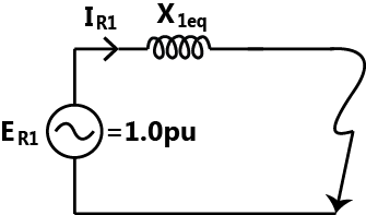
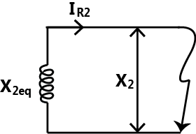
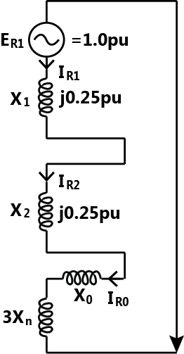
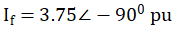
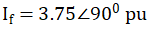
Sign in to UnlockThe positive, negative, and zero sequence reactances of a wye-connected synchronous generator are 0.2 pu, 0.2 pu and 0.1 pu, respectively. The generator is an open circuit with a terminal voltage of 1 pu. The minimum value of the inductive reactance, in pu, required to be connected between neutral and ground so that the fault current does not exceed 3.75 pu if a single line to ground fault occurs at the terminals is _________ (assume fault impedance to be zero). (Give the answer up to one decimal place.)
Sign in to see the solution
Log in to view the explanation, track your attempts, and keep your progress.
Sign in to UnlockThe magnitude of three-phase fault currents at buses A and B of a power system are 10pu and 8pu, respectively. Neglect all resistances in the system and consider the pre-fault system to be unloaded. The pre-fault voltage at all buses in the system is 1.0pu. The voltage magnitude at bus B during a three-phase fault at bus A is 0.8pu. The voltage magnitude at bus A during a three-phase fault at bus B, in pu, is_______________.
Sign in to see the solution
Log in to view the explanation, track your attempts, and keep your progress.
Sign in to UnlockA 30MVA, 3-phase, 50Hz, 13.8kV star-connected synchronous generator has positive, negative and zero sequence reactance. 15%, 15% and 5% respectively. A reactance is connected between the neutral of the generator and ground. A double line to ground fault takes place involving phase ‘b’ and ‘c’, with a fault impedance of j0.1 p.u. The value of (in p.u.) that will limit the positive sequence generator current to 4270 A is______________.


Sign in to see the solution
Log in to view the explanation, track your attempts, and keep your progress.
Sign in to UnlockA 50MVA, 10kV, 50Hz, star-connected, unloaded three-phase alternator has a synchronous reactance of 1 p.u. and a sub-transient reactance of 0.2 p.u.. If a 3-phase short circuit occurs close to the generator terminals, the ratio of initial and final values of the sinusoidal component of the short circuit current is______________.
Sign in to see the solution
Log in to view the explanation, track your attempts, and keep your progress.
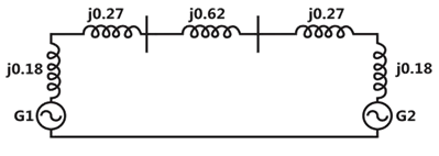
Sign in to UnlockTwo identical unloaded generators are connected in parallel as shown in the figure. Both the generators are having positive, negative and zero sequence impedance of j0.4 p.u., j0.3 p.u. and j0.15 p.u. respectively. If the pre-fault voltage is 1 p.u. for a line-to-ground (L-G) fault at the terminals at the generators, the fault current, in p.u. is______________.

Sign in to see the solution
Log in to view the explanation, track your attempts, and keep your progress.
Sign in to UnlockA sustained three-phase fault occurs in the power system shown in the figure. The current and voltage phasors during the fault (on a common reference), after the natural transients have died down are also shown. Where is the fault located?
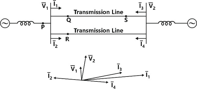
Sign in to see the solution
Log in to view the explanation, track your attempts, and keep your progress.
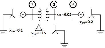
Sign in to UnlockThree – phase to ground fault takes place at locations in the system shown in the figure

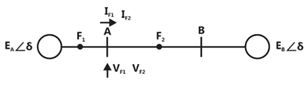
If the fault takes place at location , then the voltage and the current at bus A are and respectively. If the fault takes place at location , then the voltage and the current at bus A are respectively. The correct statement about voltages and currents during faults at is


Sign in to see the solution
Log in to view the explanation, track your attempts, and keep your progress.
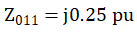
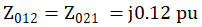
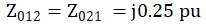
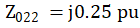
Sign in to UnlockA 2 – bus system and corresponding zero sequence network are shown in the figure.


The two transformers and are connected as,


Sign in to see the solution
Log in to view the explanation, track your attempts, and keep your progress.
Sign in to UnlockIn an unbalanced three phase system, phase current pu, negative sequence current , zero sequence current . The magnitude of phase current in pu is


Sign in to see the solution
Log in to view the explanation, track your attempts, and keep your progress.
Sign in to UnlockA three phase, 100MVA, 25kV generator has solidly grounded neutral. The positive, negative and the zero sequence reactance of the generator are 0.2pu, 0.2pu and 0.05pu, respectively, at the machine base quantities. If a bolted single phase to ground fault occurs at the terminals of the unloaded generator, the fault current in amperes immediately after the fault is_______.
Sign in to see the solution
Log in to view the explanation, track your attempts, and keep your progress.
Sign in to UnlockFor a fully transposed transmission line
Sign in to see the solution
Log in to view the explanation, track your attempts, and keep your progress.
Sign in to UnlockThe sequence components of the fault current are as follows: . The type of fault in the system is

Sign in to see the solution
Log in to view the explanation, track your attempts, and keep your progress.
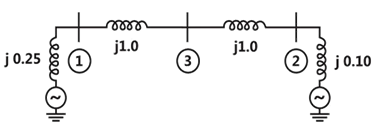
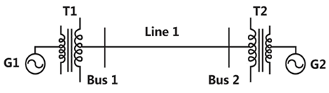
Sign in to UnlockTwo generator units G1 and G2 are connected by 15kV line with a bus at the mid-point as shown below.
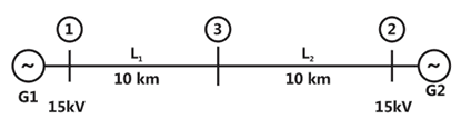
G1 = 250MVA, 15kV, positive sequence reactance X = 25% on its own base G2 = 100MVA, 15kV, positive sequence reactance X for the line = 0.225


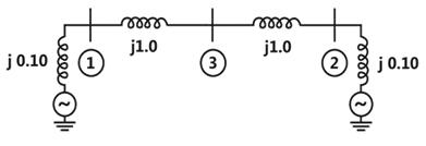
For the above system, the positive sequence diagram with the p.u. values of the 100MVA common base is
Sign in to see the solution
Log in to view the explanation, track your attempts, and keep your progress.
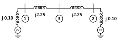
Sign in to UnlockTwo generator units G1 and G2 are connected by 15kV line with a bus at the mid-point as shown below.
G1 = 250MVA, 15kV, positive sequence reactance X = 25% on its own base G2 = 100MVA, 15kV, positive sequence reactance X for the line = 0.225
In the above system, the three-phase fault MVA at the bus 3 is
Sign in to see the solution
Log in to view the explanation, track your attempts, and keep your progress.
Sign in to UnlockFor the power system shown in the figure below. The specifications of the components are the following: [2010: 2 Marks]


Choose 25kV as the base voltage at the generator G1 and 200 MVA as the MVA base. The impedance diagram is
Sign in to see the solution
Log in to view the explanation, track your attempts, and keep your progress.
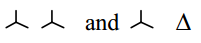
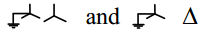
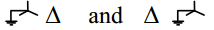
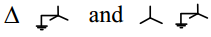
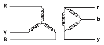
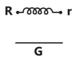
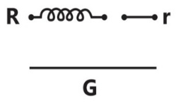
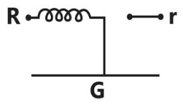
Sign in to UnlockThe zero-sequence circuit of the three phase transformers shown in the figure is
Sign in to see the solution
Log in to view the explanation, track your attempts, and keep your progress.
Sign in to UnlockA 3-phase transmission line is shown in the figure:
Voltage drop across the transmission line is given by the following equation:

Shunt capacitance of the line can be neglected. If the line has positive sequence impedance of 15Ω and zero sequence impedance of 48Ω, then the values of , and will be


Sign in to see the solution
Log in to view the explanation, track your attempts, and keep your progress.
Sign in to UnlockConsider a power system shown below:

Given that:

The positive sequence impedances are
and


3-phase Base MVA = 100
Voltage base = 400 kV (Line to Line)
Nominal system frequency = 50 Hz
The reference voltage for phase ‘a’ is defined as

A symmetrical three phase fault occurs at centre of the line. i.e. point 'F’ at time . The positive sequence impedance from source to point 'F' equals 0.004+ j0.04pu. The waveform correspond phase 'a' fault current from bus X reveals that decaying dc offset current is negative and in magnitude at its maximum initial value. Assume that the negative sequence impedances are equal to positive sequence impedances, and the zero sequence impedances are three times positive sequence impedances.


The instantof the fault will be

Sign in to see the solution
Log in to view the explanation, track your attempts, and keep your progress.
Sign in to UnlockConsider a power system shown below:
Given that:
The positive sequence impedances are and
3-phase Base MVA = 100
Voltage base = 400 kV (Line to Line)
Nominal system frequency = 50 Hz
The reference voltage for phase ‘a’ is defined as
A symmetrical three phase fault occurs at centre of the line. i.e. point 'F’ at time . The positive sequence impedance from source to point 'F' equals 0.004+ j0.04pu. The waveform correspond phase 'a' fault current from bus X reveals that decaying dc offset current is negative and in magnitude at its maximum initial value. Assume that the negative sequence impedances are equal to positive sequence impedances, and the zero sequence impedances are three times positive sequence impedances.
The RMS value of the ac component of fault currentwill be

Sign in to see the solution
Log in to view the explanation, track your attempts, and keep your progress.
Sign in to UnlockConsider a power system shown below:
Given that:
The positive sequence impedances are and
3-phase Base MVA = 100
Voltage base = 400 kV (Line to Line)
Nominal system frequency = 50 Hz
The reference voltage for phase ‘a’ is defined as
A symmetrical three phase fault occurs at centre of the line. i.e. point 'F’ at time . The positive sequence impedance from source to point 'F' equals 0.004+ j0.04pu. The waveform correspond phase 'a' fault current from bus X reveals that decaying dc offset current is negative and in magnitude at its maximum initial value. Assume that the negative sequence impedances are equal to positive sequence impedances, and the zero sequence impedances are three times positive sequence impedances.
Instead of the three phase fault, if a single line to ground fault occurs on phase 'a' at Point 'F' with zero fault impedance, then the RMS value of the ac component of fault current for phase 'a’ will be
Sign in to see the solution
Log in to view the explanation, track your attempts, and keep your progress.
Sign in to UnlockA three phase balanced star connected voltage source with frequency to rad/s is connected to a star connected balanced load which is purely inductive. The instantaneous line currents and phase to neutral voltages are denoted by and respectively, and their RMS values are denoted by V and I.


If,

then the magnitude of R is
Sign in to see the solution
Log in to view the explanation, track your attempts, and keep your progress.
Sign in to UnlockSuppose we define a sequence transformation between "a-b-c" and "p-n-o" variables as follows:
where and k is a constant. Now, if it is given that:


then,


Sign in to see the solution
Log in to view the explanation, track your attempts, and keep your progress.
Sign in to UnlockThe identical star connected resistors of 1.0pu are connected to an unbalanced 3 phase supply. The load neutral is isolated. The symmetrical components of the line voltages n pu are: . If all the pu calculations are with the respective base values, the phase to neutral sequence voltages are


Sign in to see the solution
Log in to view the explanation, track your attempts, and keep your progress.
Sign in to UnlockA generator is connected through a 20 MVA 13.8/138 kV step-up transformer, to a transmission line. At the receiving end of the line a load is supplied through a step down transformer of 10 MVA, 138/69 kV rating. A 0.72 pu load, evaluated on load side transformer ratings as base values, is supplied from the above system. For system base values of 10 MVA and 69 kV in load circuit, the value of the load (in per unit) in generator circuit will be
Sign in to see the solution
Log in to view the explanation, track your attempts, and keep your progress.
Sign in to UnlockFor a power system and admittance and impedance matrices for the fault studies are a follows:


The pre fault voltages are 1.0 p.u at all the buses. The system was unloaded prior to the fault. A solid 3 phase fault takes place at bus 2.
The post fault voltages at buses 1 and 3 in per unit respectively are
Sign in to see the solution
Log in to view the explanation, track your attempts, and keep your progress.
Sign in to UnlockFor a power system and admittance and impedance matrices for the fault studies are a follows:
The pre fault voltages are 1.0 p.u at all the buses. The system was unloaded prior to the fault. A solid 3 phase fault takes place at bus 2.
The per unit fault feeds from generators connected to buses 1 and 2 respectively are
Sign in to see the solution
Log in to view the explanation, track your attempts, and keep your progress.
Sign in to UnlockThe p.u. parameters for a 500 MVA machine on its own base are:
Inertia M = 20 p.u.; reactance X = 2 p.u.
The p.u. values of inertia and reactance on 100 MVA common base, respectively, are
Sign in to see the solution
Log in to view the explanation, track your attempts, and keep your progress.
Sign in to UnlockThe parameters of a transposed overhead transmission line are given as:
Self reactance / km and Mutual reactance


The positive sequence reactance and zero sequence reactance, respectively, in Ω/km are


Sign in to see the solution
Log in to view the explanation, track your attempts, and keep your progress.
Sign in to UnlockAt a 220 kV substation of a power system, it is given that the three-phase fault level is 4000 MVA and single-line to ground fault level is 5000 MVA. Neglecting the resistance and the shunt susceptances of the system,
(A) The positive sequence driving point reactance at the bus is:
(a) 2.5 Ω (b) 4.033 Ω
(c) 5.5 Ω (d) 12.1 Ω
(B) And the zero sequence driving point reactance at the bus is:
(a) 2.2 Ω (b) 4.84 Ω
(c) 18.18 Ω (d) 22.72 Ω
Sign in to see the solution
Log in to view the explanation, track your attempts, and keep your progress.
Sign in to UnlockAt a 220 kV substation of a power system, it is given that the three-phase fault level is 4000 MVA and single-line to ground fault level is 5000 MVA. Neglecting the resistance and the shunt susceptances of the system, the zero sequence driving point reactance at the bus is:
Sign in to see the solution
Log in to view the explanation, track your attempts, and keep your progress.
Sign in to UnlockA 3-phase generator rated at 110MVA, 11 kV is connected through circuit breakers to a transformer. The generator is having direct axis sub-transient reactance, transient reactance 26% and synchronous reactance =130%. The generator is operating at no load and rated voltage when a three phase short circuit fault occurs between the breakers and the transformer. The magnitude of initial symmetrical rims current in the breakers will be


Sign in to see the solution
Log in to view the explanation, track your attempts, and keep your progress.
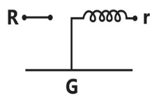
Sign in to UnlockA 3-phase transmission line supplies Δ-connected load Z. The conductor ‘c’ of the line develops an open circuit fault as shown in figure. The currents in the lines are as shown on the diagram. The positive sequence current component in line ‘a’ will be
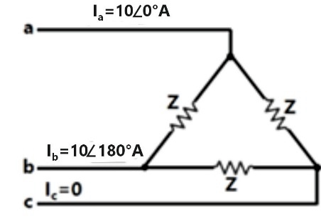


Sign in to see the solution
Log in to view the explanation, track your attempts, and keep your progress.
Sign in to UnlockA 500 MVA, 50 Hz, 3-phase turbo-generator produces power at 22 kV. Generator is Y-connected and its neutral is solidly grounded. Their sequence reactance are and . It is operating at rated voltage and disconnected from the rest of the system (no load). The magnitude of the sub-transient line current for single line ground fault at the generator terminals in p.u will be


Sign in to see the solution
Log in to view the explanation, track your attempts, and keep your progress.
Sign in to UnlockA 20-MVA, 6.6-kV, 3-phase alternator is connected to a 3-phase transmission line. The per unit positive sequence, negative sequence and zero sequence impedances of the alternator are j0.1, and j0.04 respectively. The neutral of the alternator is connected to ground through an inductive reactor of j0.05 p.u. The per unit positive, negative and zero sequence impedances of the transmission line are j0.1 and j0.3 respectively. All per unit values are based on the machine ratings. A solid ground fault occurs at one phase of the far end of the transmission line. The voltage of the alternator neutral with respect to ground during the fault is
Sign in to see the solution
Log in to view the explanation, track your attempts, and keep your progress.
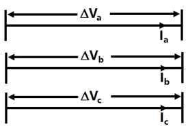
Sign in to UnlockA three-phase alternator generating unbalanced voltages is connected to an unbalanced load through a 3-phase transmission line as shown in Figure, the neutral of the alternator and the star point of the load are solidly grounded. The phase voltages of the alternator are 10∠0°, 10∠−90°V, 10∠120°V. The positive sequence component of the load current is


Sign in to see the solution
Log in to view the explanation, track your attempts, and keep your progress.
Sign in to UnlockA generator is connected to a transformer which feeds another transformer through a short feeder (see Figure). The zero sequence impedance values are expressed in pu on a common base and are indicated in Figure. The Thevenin’s equivalent zero sequence impedance at point B is
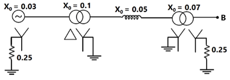
Sign in to see the solution
Log in to view the explanation, track your attempts, and keep your progress.
Sign in to UnlockTwo transposed 3 phase lines run parallel to each other, the equation describing the voltage drop in both lines is given below.

Compute the self and mutual zero sequence impedances of this system i.e. compute in the following equations


Where are the zero sequence voltage drops and currents for the two lines respectively

Sign in to see the solution
Log in to view the explanation, track your attempts, and keep your progress.
Sign in to Unlockand are steady state d-axis synchronous reactance, transient d-axis reactance and sub-transient d-axis reactance of a synchronous machine respectively. Which of the following statement is true?


Sign in to see the solution
Log in to view the explanation, track your attempts, and keep your progress.
Sign in to UnlockA 75 MVA, 10 KV, synchronous generator has The value (in p.u.) on a base of 100 MVA, 11 KV is:


Sign in to see the solution
Log in to view the explanation, track your attempts, and keep your progress.
Sign in to UnlockA 50 Hz alternator is rated 500 MVA, 20 kV, with per unit and per unit. It supplied a purely resistive load of 400 MW at 20 kV. The load is connected directly across the generator terminals when a symmetrical fault occurs at the load terminals. The initial RMS current in the generator in per unit is


Sign in to see the solution
Log in to view the explanation, track your attempts, and keep your progress.
Sign in to UnlockA single line-to-ground fault occurs on an unloaded generator in phase a positive, negative, and zero sequence impedances of the generator are j0.25p.u, j0.25p.u, and j0.15p.u. respectively. The generator neutral is grounded through a reactance of j0.05p.u. The pre fault generator terminal voltage is 1.0p.u.
The positive, negative, and zero sequence networks for the fault given are
Positive sequence diagram:
Negative sequence diagram:
Zero sequence diagram:

Interconnection of the sequence networks for the fault analysis
Sign in to see the solution
Log in to view the explanation, track your attempts, and keep your progress.
Sign in to UnlockFor given base voltage and base volt-amperes, the per unit impedance value of an element is x. What will be the per unit impedance value of this element when the voltage and volt ampere bases are both doubled?
Sign in to see the solution
Log in to view the explanation, track your attempts, and keep your progress.
Sign in to UnlockThe severity of line-to-ground and three phase faults at the terminals of an unloaded synchronous generator is to be same. If the terminal voltage is 1.0 p.u. and , for the alternator, then the required inductive reactance for neutral grounding is:


Sign in to see the solution
Log in to view the explanation, track your attempts, and keep your progress.
Sign in to UnlockFor the configuration shown in figure, the breaker connecting a large system to bus 2 is initially open. The system 3-phase fault level at bus-3 under this condition is not known. After closing the system breaker, the 3-phase fault level at bus 1 was found to be 5 p.u. What will be the new 3-phase fault level at system bus 3 after the interconnection? All unit values are on common bases. Per fault load current are neglected and pre fault voltages are assumed to be 1.0 p.u. at all buses.
Sign in to see the solution
Log in to view the explanation, track your attempts, and keep your progress.
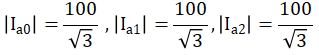
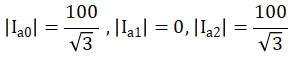
Sign in to UnlockDetermine the magnitudes of the symmetrical components of the currents in a three phase (RYB) three wire system, when a short circuit occurs between R and Y phase wires, the fault current being 100A.

Sign in to see the solution
Log in to view the explanation, track your attempts, and keep your progress.
Sign in to UnlockFor the network shown in fig, the zero sequence reactance’s in p.u. are indicated. The zero sequence driving point reactance of the node 3 is:
Sign in to see the solution
Log in to view the explanation, track your attempts, and keep your progress.
Sign in to UnlockFor a fault at the terminals of a synchronous generator, the fault current is maximum for a
Sign in to see the solution
Log in to view the explanation, track your attempts, and keep your progress.
Sign in to UnlockThe synchronous reactance of a 200 MVA, 10kV, 3-phase, 50Hz generator is 1.0p.u. at its own base. Its p.u. reactance at 100MVA, 20 kV base will be……
Sign in to see the solution
Log in to view the explanation, track your attempts, and keep your progress.
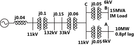
Sign in to UnlockThe system shown in figure feeds two loads-
(a) a factory load of 15 MVA consisting of induction motors and (b) a domestic load of 10MW at 0.8p.f. lagging at 6kV. If the induction motors are rated at 6 kV and take 5 times their rated current at zero p.f. at starting, calculate the dip in voltage at the domestic load bus bar when all the induction motors are started at the same time.
Sign in to see the solution
Log in to view the explanation, track your attempts, and keep your progress.
Sign in to UnlockFor an unbalanced fault, with paths for zero sequence currents, at the point of fault
Sign in to see the solution
Log in to view the explanation, track your attempts, and keep your progress.
Sign in to UnlockThe positive sequence component of the voltage at the point of fault in a power system is zero for a 3 – phase fault. (True=1/False=0)
Sign in to see the solution
Log in to view the explanation, track your attempts, and keep your progress.
Sign in to UnlockA three phase star-connected alternator is rated 30 MVA, 13.8 kV and has the following sequence reactance values:

The neutral of the alternator is solidly grounded. Determine the alternator line currents when a double line-to-ground fault occurs on its terminals. Assume that the alternator is unloaded and is operating at rated voltage when the fault occurs.

Sign in to see the solution
Log in to view the explanation, track your attempts, and keep your progress.
Sign in to UnlockIn a power-system, the 3-phase fault MVA is always higher than the single-line-to-ground fault MVA at a bus. (True=1/False=0)
Sign in to see the solution
Log in to view the explanation, track your attempts, and keep your progress.
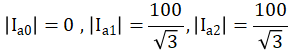
Sign in to UnlockA fault occurring at the terminals at the terminals of an unloaded synchronous generator operating at its rated voltage has resulted in the following values of current and voltage


The fault that has occurred is _________________.
Sign in to see the solution
Log in to view the explanation, track your attempts, and keep your progress.
Sign in to UnlockA 100 MVA generator with 10% reactance and a 200 MVA generator with 8% reactance (reactances on their own bases) are connected as shown in figure. The fault level on bus 1 is to be restricted to 1500 MVA. Calculate, on 100 MVA base.
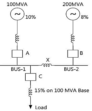
(i) The reactance of bus bar reactor X
(ii) Fault level of bus 2
(iii) MVA rating of circuit breaker C
Sign in to see the solution
Log in to view the explanation, track your attempts, and keep your progress.
Sign in to Unlock