Control Systems
Time Response Analysis
Practice questions from Time Response Analysis.
55
Total0
Attempted0
Correct0
IncorrectThe Laplace transform of the step response of a system is given by

The rise time is defined as the time taken for the response to go from 0.1 to 0.9 of its final value. The settling time is defined as the time taken for the response to reach 0.98 of its final value.
For this system, the rise time ( ), settling time ( ), and time constant ( ), all expressed in seconds, are


Sign in to see the solution
Log in to view the explanation, track your attempts, and keep your progress.
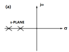
Sign in to UnlockConsider the standard second-order system of the form with the poles and having negative real parts. The pole locations are also shown in the figure. Now consider two such second-order systems as defined below:


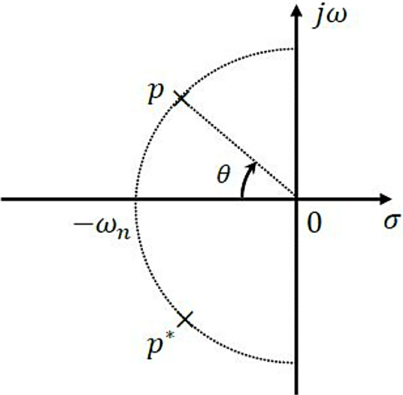
System 1: and


System 2: and


Which one of the following statements is correct?
Sign in to see the solution
Log in to view the explanation, track your attempts, and keep your progress.
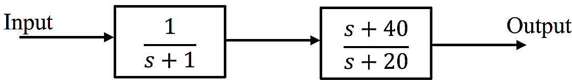
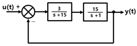
Sign in to UnlockConsider the cascaded system as shown in the figure. Neglecting the faster component of the transient response, which one of the following options is a first order pole-only approximation such that the steady-state values of the unit step responses of the original and the approximated systems are same?


Sign in to see the solution
Log in to view the explanation, track your attempts, and keep your progress.
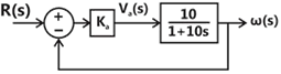
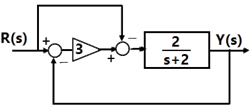
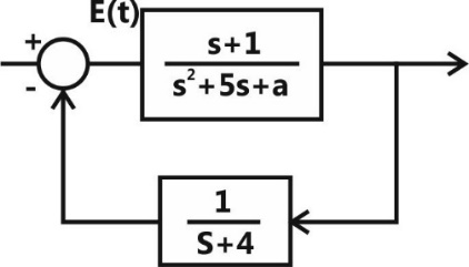
Sign in to UnlockThe damping ratio and undamped natural frequency of a closed loop system as shown in the figure, are denoted as and ωn, respectively. The values of and are


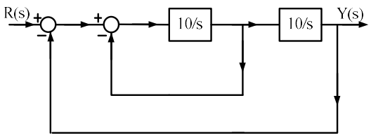
= 0.5 and = 10 rad/s

= 0.1 and = 10 rad/s
= 0.707 and = 10 rad/s
= 0.707 and = 100 rad/s
Sign in to see the solution
Log in to view the explanation, track your attempts, and keep your progress.
Sign in to UnlockConsider a permanent magnet dc (PMDC) motor which is initially at rest. At t = 0, a dc voltage of 5 V is applied to the motor. Its speed monotonically increases from 0 rad/s to 6.32 rad/s in 0.5 s and finally settles to 10 rad/s. Assuming that the armature inductance of the motor is negligible, the transfer function for the motor is


Sign in to see the solution
Log in to view the explanation, track your attempts, and keep your progress.
Sign in to UnlockThe output response of a system is denoted as y(t), and its Laplace transform is given by the steady state value of y(t) is


Sign in to see the solution
Log in to view the explanation, track your attempts, and keep your progress.
Sign in to UnlockConsider a unity feedback system with forward transfer function given by

The steady-state error in the output of the system for a unit-step input is______(up to 2 decimal places).
Sign in to see the solution
Log in to view the explanation, track your attempts, and keep your progress.
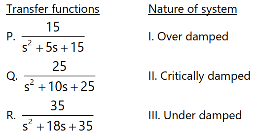
Sign in to UnlockMatch the transfer functions of the second-order systems with the nature of the systems given below.
Sign in to see the solution
Log in to view the explanation, track your attempts, and keep your progress.
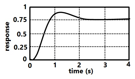
Sign in to UnlockThe unit step response y(t) of a unity feedback system with open loop transfer function is shown in the figure.

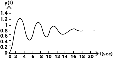
The value of K is ________ (up to decimal places).
Sign in to see the solution
Log in to view the explanation, track your attempts, and keep your progress.
Sign in to UnlockFor a system having transfer function, a unit step input is applied at time t= 0. The value of the response of the system at t = 1.5 sec. (rounded off to three decimal places) is

Sign in to see the solution
Log in to view the explanation, track your attempts, and keep your progress.
Sign in to UnlockWhen a unit ramp input is applied to the unity feedback system having closed loop transfer function , the steady rate error will be

0


Sign in to see the solution
Log in to view the explanation, track your attempts, and keep your progress.
Sign in to UnlockWhich of the following systems has maximum peak overshoot due to a unit step input?


Sign in to see the solution
Log in to view the explanation, track your attempts, and keep your progress.
Sign in to UnlockA second-order real system has the following properties:
(a) the damping ratio and undamped natural frequency ,


(b) the steady state value of the output, to a unit step input, is 1.02
The transfer function of the system is


Sign in to see the solution
Log in to view the explanation, track your attempts, and keep your progress.
Sign in to UnlockAn open loop control system results in a response of for a unit impulse input. The DC gain of the control system is ___________.

Sign in to see the solution
Log in to view the explanation, track your attempts, and keep your progress.
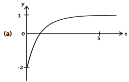
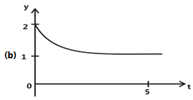
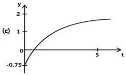
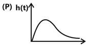
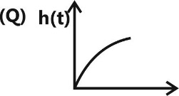
Sign in to UnlockThe unit step response of a system with the transfer function is given by which one of the following waveforms?

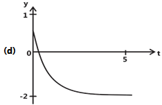
Sign in to see the solution
Log in to view the explanation, track your attempts, and keep your progress.
Sign in to UnlockThe closed-loop transfer function of a system is . The steady state error due to unit step input is_____________.

Sign in to see the solution
Log in to view the explanation, track your attempts, and keep your progress.
Sign in to UnlockAssuming zero initial condition, the response y(t) of the system given below to a unit step input u(t) is
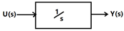
u(t)
t u(t)


Sign in to see the solution
Log in to view the explanation, track your attempts, and keep your progress.
Sign in to UnlockThe open-loop transfer function of a dc motor is given as. When connected in feedback as shown below, the approximate value of that will reduce the time constant of the closed loop system by one hundred times as compared to that of the open-loop system is


Sign in to see the solution
Log in to view the explanation, track your attempts, and keep your progress.
Sign in to UnlockThe steady state error of a unity feedback linear system for a unit step input is 0.1. The steady state error of the same system, for a pulse input r(t) having a magnitude of 10 and a duration of one second, as shown in the figure is
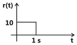
Sign in to see the solution
Log in to view the explanation, track your attempts, and keep your progress.
Sign in to UnlockFor the system , the approximate time taken for a step response to reach 98% of its final value is

Sign in to see the solution
Log in to view the explanation, track your attempts, and keep your progress.
Sign in to UnlockThe unit-step response of a unity feedback system with open loop transfer function is shown in the figure. The value of K is

Sign in to see the solution
Log in to view the explanation, track your attempts, and keep your progress.
Sign in to UnlockThe transfer function of a linear time invariant system is given as

The steady state value of the output of this system for a unit impulse input applied at time instant t = 1 will be
Sign in to see the solution
Log in to view the explanation, track your attempts, and keep your progress.
Sign in to UnlockThe transfer function of a system is given as

This system is
Sign in to see the solution
Log in to view the explanation, track your attempts, and keep your progress.
Sign in to UnlockConsider the feedback control system shown below which is subjected to a unit step input. The system is stable and has the following parameters and


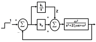
The steady state value of z is
Sign in to see the solution
Log in to view the explanation, track your attempts, and keep your progress.
Sign in to UnlockConsider the R-L-C circuit shown in figure.
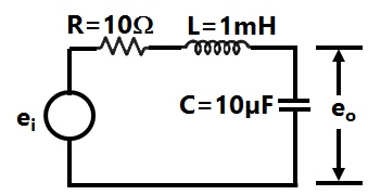
For a step-input, the overshoot in the output will be


Sign in to see the solution
Log in to view the explanation, track your attempts, and keep your progress.
Sign in to UnlockConsider the R-L-C circuit shown in figure.
If the above step response is to be observed on a non-storage CRO, then it would be best to have the , as a

Sign in to see the solution
Log in to view the explanation, track your attempts, and keep your progress.
Sign in to UnlockWhen subjected to a unit step input, the closed loop control system shown in Figure will have a steady state error of
Sign in to see the solution
Log in to view the explanation, track your attempts, and keep your progress.
Sign in to UnlockConsider the function , where F(s) is the Laplace transform of the function f(t). The initial value of f(t) is equal to

5


0
Sign in to see the solution
Log in to view the explanation, track your attempts, and keep your progress.
Sign in to UnlockThe block diagram of a closed loop control system is given by figure. The values of K and P such that the system has a damping ratio of 0.7 and an un-damped natural frequency of 5rad/sec, are respectively equal to
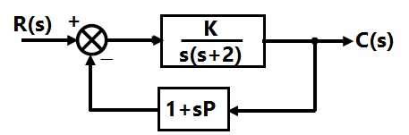
Sign in to see the solution
Log in to view the explanation, track your attempts, and keep your progress.
Sign in to UnlockThe unit impulse response of a second order under-damped system starting from rest is given by

The steady-state value of the unit step response of the system is equal to
Sign in to see the solution
Log in to view the explanation, track your attempts, and keep your progress.
Sign in to UnlockA control system is defined by the following mathematical relationship

The response of the system as t →∞ is
Sign in to see the solution
Log in to view the explanation, track your attempts, and keep your progress.
Sign in to UnlockA control system with certain excitation is governed by the following mathematical equation

The natural time constants of the response of the system are
Sign in to see the solution
Log in to view the explanation, track your attempts, and keep your progress.
Sign in to UnlockThe block diagram shown in Figure gives a unity feedback closed loop control system. The steady state error in the response of the above system to unit step input is
Sign in to see the solution
Log in to view the explanation, track your attempts, and keep your progress.
Sign in to UnlockThe roots of the closed loop characteristic equation of the system shown in above figure are
Sign in to see the solution
Log in to view the explanation, track your attempts, and keep your progress.
Sign in to UnlockGiven the relationship between the input u(t) and the output y(t) to be, the transfer function is


Sign in to see the solution
Log in to view the explanation, track your attempts, and keep your progress.
Sign in to UnlockA unity feedback system has open loop transfer function G(s). The steady-state error is zero for
Sign in to see the solution
Log in to view the explanation, track your attempts, and keep your progress.
Sign in to UnlockA linear time-invariant system initially at rest, when subjected to a unit-step input, gives a response,. The transfer function of the system is:


Sign in to see the solution
Log in to view the explanation, track your attempts, and keep your progress.
Sign in to UnlockA unity feedback system has open loop transfer function. The peak overshoot in the step-input response of the system is approximately equal to:

Sign in to see the solution
Log in to view the explanation, track your attempts, and keep your progress.
Sign in to UnlockThe output of a linear time invariant control system is c(t) for a certain input r(t). If r(t) modified by passing it through a block whose transfer function is and then applied to the system, the modified output of the system would be


Sign in to see the solution
Log in to view the explanation, track your attempts, and keep your progress.
Sign in to UnlockThe Laplace transform of is:


None of the above
Sign in to see the solution
Log in to view the explanation, track your attempts, and keep your progress.
Sign in to UnlockA first order system is initially at rest and excited by a step input at time t=0. Its output becomes 1.1V is in 4 seconds and eventually reacts a steady state value of 2V. Determine its time constant
Sign in to see the solution
Log in to view the explanation, track your attempts, and keep your progress.
Sign in to UnlockThe unit-impulse response of a unit-feedback control system is given by

The open loop transfer function is equal to


Sign in to see the solution
Log in to view the explanation, track your attempts, and keep your progress.
Sign in to UnlockConsider the unit-step response of a unity-feedback control system whose open-loop transfer functions is . The maximum overshoot is equal to

Sign in to see the solution
Log in to view the explanation, track your attempts, and keep your progress.
Sign in to UnlockFor a feedback control system of type 2, the steady state error for a ramp input is
Sign in to see the solution
Log in to view the explanation, track your attempts, and keep your progress.
Sign in to UnlockFor the system shown in figure, with a damping ratio of 0.7 and an undamped natural frequency

of 4 rad/sec, the values of K and a are


Sign in to see the solution
Log in to view the explanation, track your attempts, and keep your progress.
Sign in to UnlockThe unit impulse response of a system is given as . The step response of the same system for is equal to


Sign in to see the solution
Log in to view the explanation, track your attempts, and keep your progress.
Sign in to UnlockThe impulse response of an initially relaxed linear system is . To produce a response of , the input must be equal to


Sign in to see the solution
Log in to view the explanation, track your attempts, and keep your progress.
Sign in to UnlockThe closed loop transfer function of a control system is given by

For a unit step input the output is
zero
infinity
Sign in to see the solution
Log in to view the explanation, track your attempts, and keep your progress.
Sign in to UnlockThe Laplace transform of f(t) is F(s). Given , the final value of f(t) is :

Sign in to see the solution
Log in to view the explanation, track your attempts, and keep your progress.
Sign in to UnlockThe steady state error due to a step input for type 1 system is _______________
Sign in to see the solution
Log in to view the explanation, track your attempts, and keep your progress.
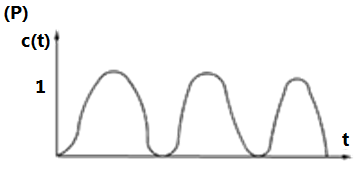
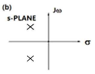
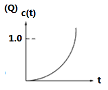
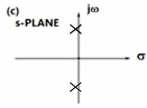
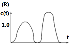
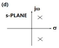
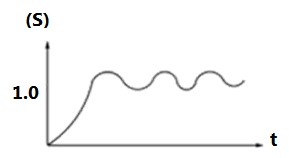
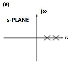
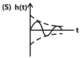
Sign in to UnlockRoot locations of the characteristic unit step responses of second order of second equations order systems
Sign in to see the solution
Log in to view the explanation, track your attempts, and keep your progress.
Sign in to UnlockIf f(t) is the step-response of a linear-time invariant system, then its impulse response is given by .
(True=1, False=0)

Sign in to see the solution
Log in to view the explanation, track your attempts, and keep your progress.
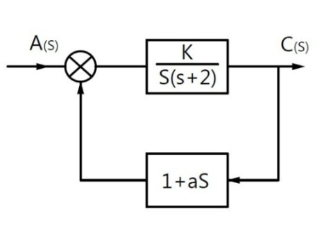
Sign in to UnlockFor what values of ‘a’ does the system shown in figure have a zero steady state error for a step input?


a=10

for no value of ‘a’
Sign in to see the solution
Log in to view the explanation, track your attempts, and keep your progress.
Sign in to UnlockMatch the following transfer functions and impulse responses
Transfer functions | |
(a) | |
(b) | |
(c) | |
(d) |


Sign in to see the solution
Log in to view the explanation, track your attempts, and keep your progress.
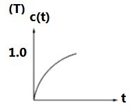
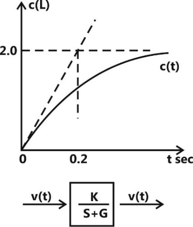
Sign in to UnlockA first order system and its response to a unit step input are shown in figure. The system parameters are
a= _______________
K= _______________
Sign in to see the solution
Log in to view the explanation, track your attempts, and keep your progress.
Sign in to Unlock