Network Analysis
Transient Analysis
Practice questions from Transient Analysis.
48
Total0
Attempted0
Correct0
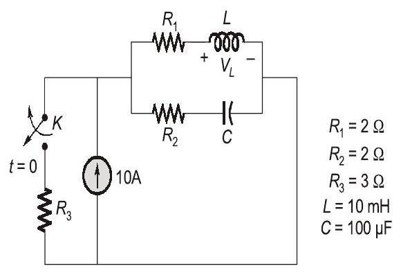
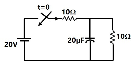
IncorrectThe electrical network shown has an independent voltage source (10 V) and a current source ( ).

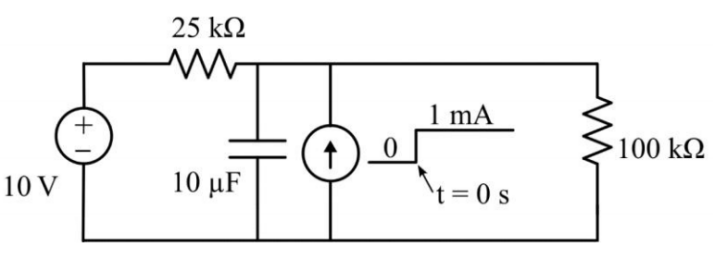
The voltage across the capacitor at time instants (in seconds) , and , respectively, is:


Sign in to see the solution
Log in to view the explanation, track your attempts, and keep your progress.
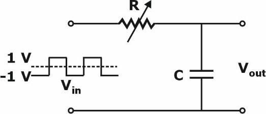
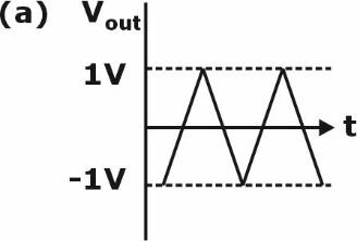
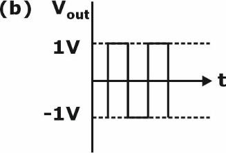
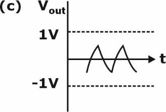
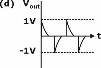
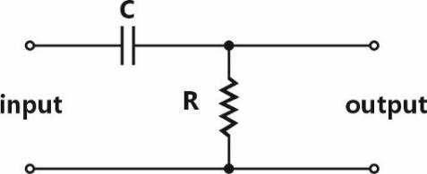
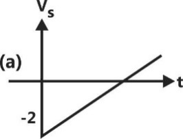
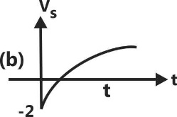
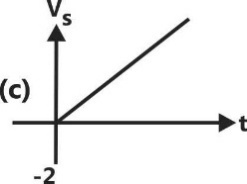
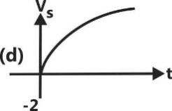
Sign in to UnlockIn the circuit, shown below, if the values of R and C are very large, the form of the
output voltage for a very high frequency square wave input, is best represented by
Sign in to see the solution
Log in to view the explanation, track your attempts, and keep your progress.
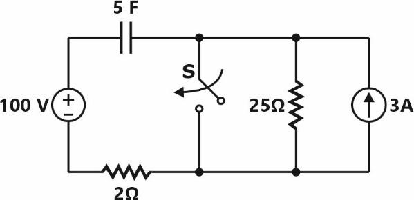
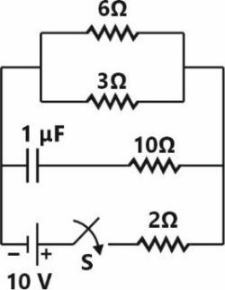
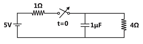
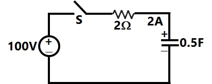
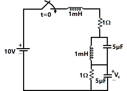
Sign in to UnlockThe switch (S) closes at . The time, in sec, the capacitor takes to charge to 50 V is ________ (round off to one decimal place).

Sign in to see the solution
Log in to view the explanation, track your attempts, and keep your progress.
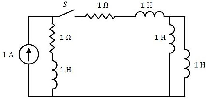
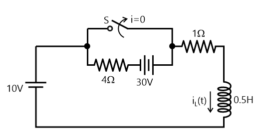
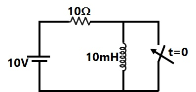
Sign in to UnlockThe circuit shown in the figure with the switch S open, is in steady state. After the switch S is closed, the time constant of the circuit in seconds is
Sign in to see the solution
Log in to view the explanation, track your attempts, and keep your progress.
Sign in to UnlockThe value of parameters of the circuit shown in the figure are :

For time , the circuit is at steady state with the switch ' ' in closed condition. If the switch is opened at , the value of the voltage across the inductor at in Volts is ________ (Round off to 1 decimal place).


Sign in to see the solution
Log in to view the explanation, track your attempts, and keep your progress.
Sign in to UnlockIn the circuit shown below, the switch Sis closed at t = 0. The magnitude of the steady state voltage, in volts, across the 6Ω resistor is_________ (round off to two decimal places).
Sign in to see the solution
Log in to view the explanation, track your attempts, and keep your progress.
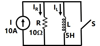
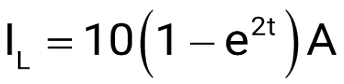
Sign in to UnlockIn the circuit, switch 'S’ is in the closed position for a very long time if the switch is opened at time t = 0, then iL(t) in amperes, for t > 0 is
10


Sign in to see the solution
Log in to view the explanation, track your attempts, and keep your progress.
Sign in to UnlockA 100 Hz square wave, switching between 0V and 5V, is applied to a CR high-pass filter circuit as shown, The output voltage waveform across the resistor is 6.2V peak-to-peak, If the resistance R is 820Ω. then the value C is_________ μF. (Round off to 2 decimal places.)
Sign in to see the solution
Log in to view the explanation, track your attempts, and keep your progress.
Sign in to UnlockA resistor and a capacitor are connected in series to a 10 V DC supply through a switch. The switch is closed at t=0, and the capacitor voltage is found to cross 0V at t=0.4τ, where τ is the circuit time constant. The absolute value of percentage change required in the initial capacitor voltage if the zero crossing has to happen at t=0.2τ is_________ (rounded off to 2 decimal places).
Sign in to see the solution
Log in to view the explanation, track your attempts, and keep your progress.
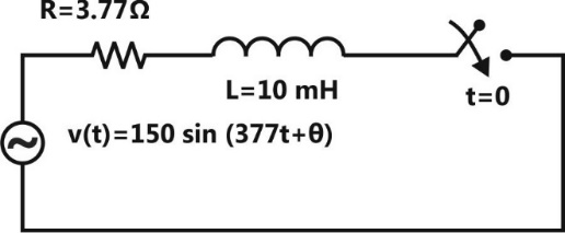
Sign in to UnlockIn the circuit shown below, the switch is closed at t=0. The value of in degrees which will give the maximum value of DC offset of the current at the time of switching is

Sign in to see the solution
Log in to view the explanation, track your attempts, and keep your progress.
Sign in to UnlockA 0.1capacitor charged to 100 V is discharged through a resistor. The time in ms (round off to two decimal places) required for the voltage across the capacitor to drop to 1 V is ___________


Sign in to see the solution
Log in to view the explanation, track your attempts, and keep your progress.
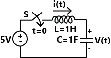
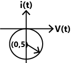
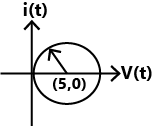
Sign in to UnlockA DC voltage source is connected to a series L-C circuit by taming on the switch S at time t-0 as shown in the figure. Assume. Which one of the following circular loci represents the plot of i(t) versus v(t)?

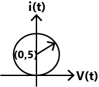
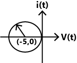
Sign in to see the solution
Log in to view the explanation, track your attempts, and keep your progress.
Sign in to UnlockThe switch in the figure below was closed for a long time. It is opened at t = 0. The current in the inductor of 2 H for, is

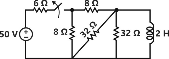


Sign in to see the solution
Log in to view the explanation, track your attempts, and keep your progress.
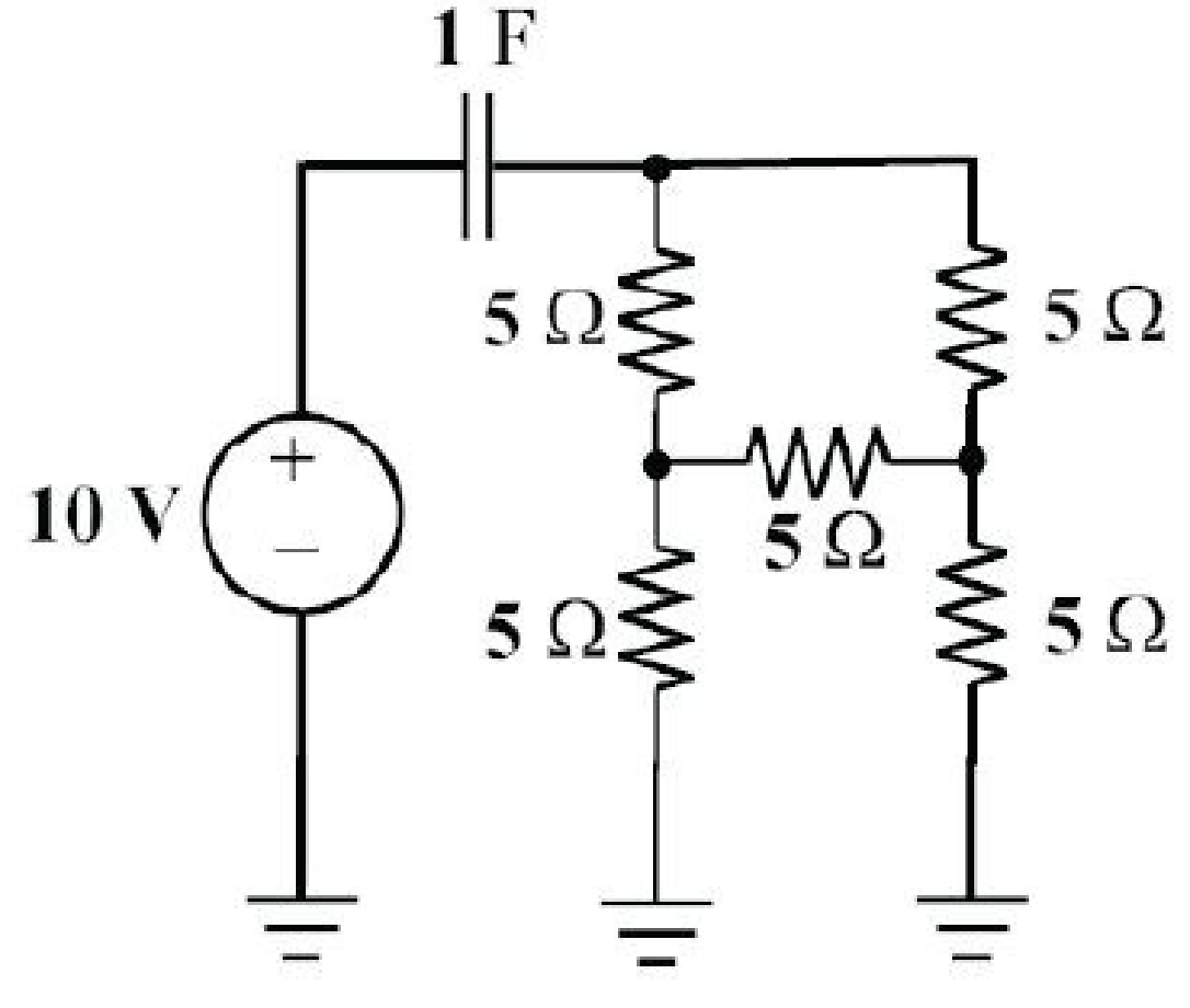
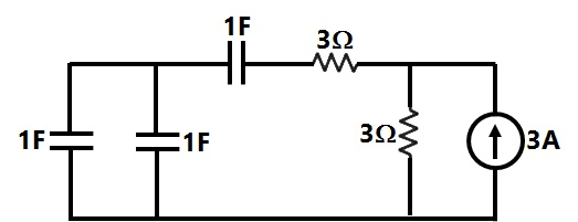
Sign in to UnlockThe initial charge in the 1 F capacitor present in the circuit shown is zero. The energy in joules transferred from the DC source until steady state condition is reached equals ________ . (Give the answer up to one decimal place).
Sign in to see the solution
Log in to view the explanation, track your attempts, and keep your progress.
Sign in to UnlockIn the circuit shown, switch has been closed for a long time. At time t = 0 switch is closed. At , the rate of change of current through the inductor, in amperes per second, is _____________.


Sign in to see the solution
Log in to view the explanation, track your attempts, and keep your progress.
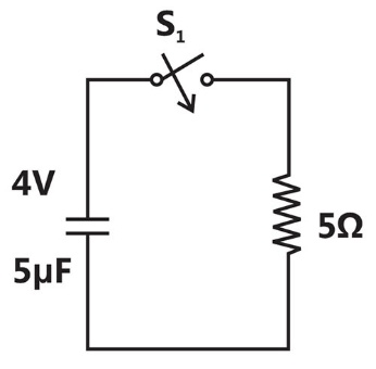
Sign in to UnlockIn the circuit shown below, the initial capacitor voltage is 4V, Switch \(S_1\) is closed at t = 0. The charge (in ) lost by the capacitor from t = 25 micro sec. to is ______________.


Sign in to see the solution
Log in to view the explanation, track your attempts, and keep your progress.
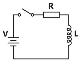
Sign in to UnlockA series RL circuit is excited at t = 0 by closing a switch as shown in the figure. Assuming zero initial conditions, the value of at t = 0 is


0

Sign in to see the solution
Log in to view the explanation, track your attempts, and keep your progress.
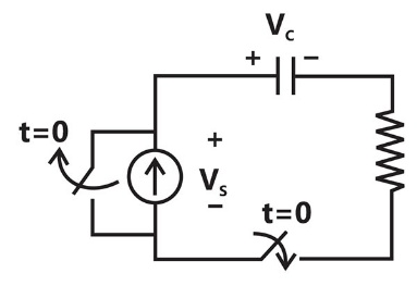
Sign in to UnlockA combination of capacitor with an initial voltage in series with a resistor is connected to a 20mA ideal dc current source by operating both switches at t = 0 s as shown. Which of the following graphs shown in the options approximates the voltage across the current source over the next few seconds?


Sign in to see the solution
Log in to view the explanation, track your attempts, and keep your progress.
Sign in to UnlockThe switch SW shown in the circuit is kept at position ‘1’ for a long duration. At t = 0+, the switch is moved to position ‘2’. Assuming, the voltage across the capacitor is


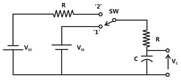


Sign in to see the solution
Log in to view the explanation, track your attempts, and keep your progress.
Sign in to UnlockThe driving point impedance Z(s) for the circuit shown below is
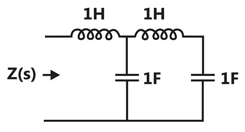


Sign in to see the solution
Log in to view the explanation, track your attempts, and keep your progress.
Sign in to UnlockThe switch in the circuit has been closed for a long time. It is opened at t = 0. At , the current through the line capacitor is

Sign in to see the solution
Log in to view the explanation, track your attempts, and keep your progress.
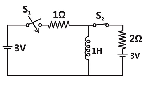
Sign in to UnlockIn the figure shown, all elements used are ideal. For time t < 0, \(S_1\) remained closed and \(S_2\) open. At
t = 0, \(S_1\) is opened and \(S_2\) is closed. If the voltage \(Vc_2\) across the capacitor \(C_2\) at t = 0 is zero, the voltage across the capacitor combination at will be

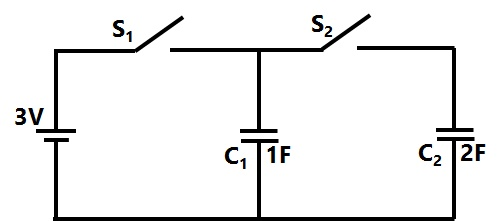
Sign in to see the solution
Log in to view the explanation, track your attempts, and keep your progress.
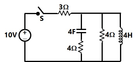
Sign in to UnlockThe time constant for the given circuit will be


4s
9s
Sign in to see the solution
Log in to view the explanation, track your attempts, and keep your progress.
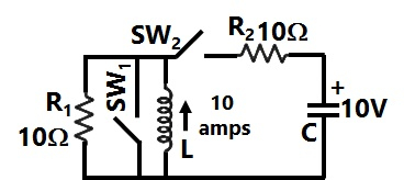
Sign in to UnlockIn the circuit shown in figure switch \(SW_1\), is initially CLOSED and \(SW_2\) is OPEN. The inductor L carries a current of 10A and the capacitor is charged to 10 V with polarities as indicated. \(SW_2\), is initially CLOSED at and \(SW_1\), is OPENED at t=0. The current through C and the voltage across L at is
Sign in to see the solution
Log in to view the explanation, track your attempts, and keep your progress.
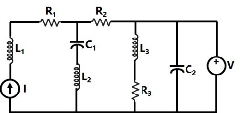
Sign in to UnlockIn the circuit shown in the figure, the current source I = 1A, voltage source V = 5V, , ,


In steady state, the currents (in A) through R3 and the voltage source V respectively will be
Sign in to see the solution
Log in to view the explanation, track your attempts, and keep your progress.
Sign in to UnlockAn ideal capacitor is charged to a voltage V0 and connected at t = 0 across an ideal inductor L. (The circuit now consists of a capacitor and inductor alone). If we let , the voltage across the capacitor at time t > 0 is given by

V0


Sign in to see the solution
Log in to view the explanation, track your attempts, and keep your progress.
Sign in to UnlockIn Figure, the initial capacitor voltage is zero. The switch is closed at t = 0. The final steady-state voltage across the capacitor is:
Sign in to see the solution
Log in to view the explanation, track your attempts, and keep your progress.
Sign in to UnlockThe circuit shown in Figure is in steady state, when the switch is closed at t = 0. Assuming that the inductance is ideal, the current through the inductor at equals
Sign in to see the solution
Log in to view the explanation, track your attempts, and keep your progress.
Sign in to UnlockA coil of inductance 10H resistance is connected as shown in figure. After the switch S has been in connected with point 1 for a very long time, it is moved to point 2 at t=0

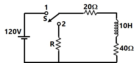
If, at t = 0+, the voltage across the coil is 120V, the value of resistance R is:
Sign in to see the solution
Log in to view the explanation, track your attempts, and keep your progress.
Sign in to UnlockA coil of inductance 10H resistance is connected as shown in figure. After the switch S has been in connected with point 1 for a very long time, it is moved to point 2 at t=0
For the value of R =40 ohm, the time taken for 95% of the stored energy dissipated is close to
Sign in to see the solution
Log in to view the explanation, track your attempts, and keep your progress.
Sign in to UnlockIn figure, the capacitor initially has a charge of 10 Coulomb. The current in the circuit one second after the switch S is closed will be
Sign in to see the solution
Log in to view the explanation, track your attempts, and keep your progress.
Sign in to UnlockThe RMS value of the resultant current in a wire which carries a dc current of 10 A and a sinusoidal alternating current of peak value 20 A is
Sign in to see the solution
Log in to view the explanation, track your attempts, and keep your progress.
Sign in to UnlockIn the circuit shown in Figure, the switch S is closed at time t = 0. The voltage across the inductance at
, is
Sign in to see the solution
Log in to view the explanation, track your attempts, and keep your progress.
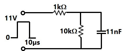
Sign in to UnlockAn 11 V pulse of 10 µs duration is applied to the circuit shown in Figure. Assuming that the capacitor is completely discharged prior to applying the pulse, the peak value of the capacitor voltage is
Sign in to see the solution
Log in to view the explanation, track your attempts, and keep your progress.
Sign in to UnlockIn the circuit shown in Figure, the switch is closed at time t = 0. The steady state value of the voltage is

Sign in to see the solution
Log in to view the explanation, track your attempts, and keep your progress.
Sign in to UnlockA constant current source is supplying 10A to a circuit shown in Figure. The switch S, which is initially closed for a sufficiently long time, is suddenly opened. Obtain obtain the complete time response of the inductor current. What is the energy stored in L, a long time after the switch is opened?
E=250J

E=250J
E=250J
E=350J
Sign in to see the solution
Log in to view the explanation, track your attempts, and keep your progress.
Sign in to UnlockA unit step voltage is applied at t = 0 to a series RL circuit with zero initial conditions.
It is possible for the current to be oscillatory.
The voltage across the resistor at is zero.
The energy stored in the inductor in the steady state is zero.
The resistor current eventually falls to zero.
Sign in to see the solution
Log in to view the explanation, track your attempts, and keep your progress.
Sign in to UnlockA voltage waveform is applied across a 1H inductor for , with initial current through it being zero. The current through the inductor for is given by


Sign in to see the solution
Log in to view the explanation, track your attempts, and keep your progress.
Sign in to UnlockA rectangular voltage pulse of magnitude V and duration T is applied to a series combination of resistance R and capacitance C. The maximum voltage developed across the capacitor is:


v

Sign in to see the solution
Log in to view the explanation, track your attempts, and keep your progress.
Sign in to UnlockWhen a periodic triangular voltage peak amplitude 1V and frequency 0.5Hz is applied to a parallel combination of 1Ω resistance and 1F capacitance, the current through the voltage source has wave-form
Sign in to see the solution
Log in to view the explanation, track your attempts, and keep your progress.
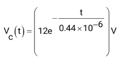
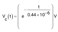
Sign in to UnlockIn the circuit shown in figure, capacitor is initially charged to 12V. Find the mathematical expression for the voltage across the capacitor after closing the switch at t=0

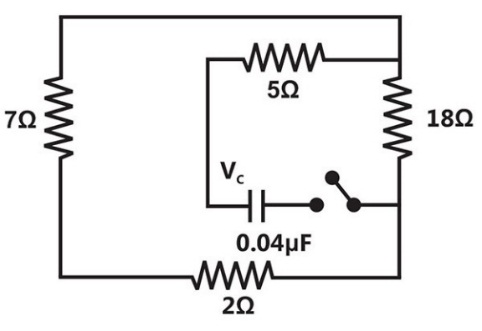
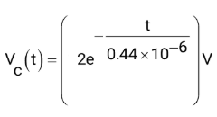
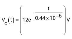
Sign in to see the solution
Log in to view the explanation, track your attempts, and keep your progress.
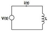
Sign in to UnlockIn the circuit shown in figure, it is desired to have a constant direct current i(t) through the ideal inductor L. the nature of the voltage source v(t) must be:
Sign in to see the solution
Log in to view the explanation, track your attempts, and keep your progress.
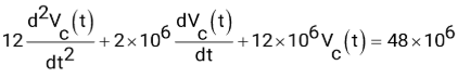
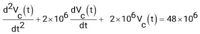
Sign in to UnlockThe switch in the following circuit, shown in fig 3, has been connected to the 12 V source for a long time. At t=0, the switch is thrown to 24V. The value of L=2H,


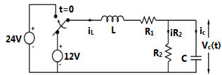
(a) Determine and


(b) Write the differential equation governing for t>0

(c) Compute the steady state value of

(a) 1A, 2V
(b)
(c) =4V
(a) 1A, 1V
(b)
(c) =4V
(a) 1A, 2V
(b)
(c) =4V

(a) 1A, 2V
(b)
(c) =8V
Sign in to see the solution
Log in to view the explanation, track your attempts, and keep your progress.
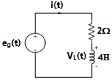
Sign in to UnlockIn the circuit shown in figure. eg(t)=2.5t volts. What are the values of i(t) and VL(t) at t=4 seconds?
Sign in to see the solution
Log in to view the explanation, track your attempts, and keep your progress.
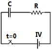
Sign in to UnlockIn the series RC circuit shown in figure the voltage across C starts increasing when the d.c. source is switched on. The rate of increase of voltage across C at the instant just after the switch is closed
(i.e., at ), will be
Sign in to see the solution
Log in to view the explanation, track your attempts, and keep your progress.
Sign in to UnlockThe time constant of the network shown in figure, is
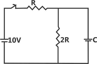
2RC
3RC


Sign in to see the solution
Log in to view the explanation, track your attempts, and keep your progress.
Sign in to UnlockTwo coils having equal resistance but different inductances are connected in series.
The time-constant of the series combination is:
Sign in to see the solution
Log in to view the explanation, track your attempts, and keep your progress.
Sign in to UnlockThe switch S in figure is closed at t=0. If and respectively, voltages across the capacitors in steady state will be :


Sign in to see the solution
Log in to view the explanation, track your attempts, and keep your progress.
Sign in to Unlock