Network Analysis
Magnetically Coupled Circuits
Practice questions from Magnetically Coupled Circuits.
11
Total0
Attempted0
Correct0
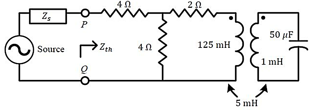
IncorrectFor the circuit shown in the figure, the source frequency is . The mutual inductance between the magnetically coupled inductors is with their self inductances being and . The Thevenin's impedance, , between the terminals and Q in is _______ (rounded off to 2 decimal places).


Sign in to see the solution
Log in to view the explanation, track your attempts, and keep your progress.
Sign in to UnlockThe input impedance , for the network shown in

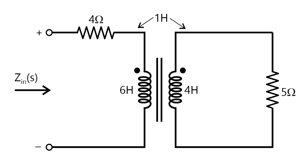
7s + 4


6s + 4
Sign in to see the solution
Log in to view the explanation, track your attempts, and keep your progress.
Sign in to UnlockTwo identical coils are each having inductance L are placed together on the some core. If an overall inductance of is obtained by interconnecting these two coils, the minimum value of is _______________.


Sign in to see the solution
Log in to view the explanation, track your attempts, and keep your progress.
Sign in to UnlockTwo identical coupled inductors are connected is series. The measured inductance for the two possible series connections are , Their mutual inductance in is __________


Sign in to see the solution
Log in to view the explanation, track your attempts, and keep your progress.
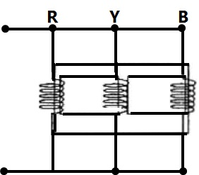
Sign in to UnlockThe three limbed non ideal core shown in the figure has three windings with nominal inductances L each when measured individually with a single phase AC source.
The inductance of the windings as connected will be
Sign in to see the solution
Log in to view the explanation, track your attempts, and keep your progress.
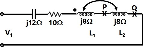
Sign in to UnlockIn the circuit shown in Figure, it is found that the input ac voltage (v) and current I are in phase. The coupling coefficient is , where M is the mutual inductance between the two coils. The value of K and the dot polarity of the coil P-Q are

Sign in to see the solution
Log in to view the explanation, track your attempts, and keep your progress.
Sign in to UnlockGiven two coupled inductors and , their mutual inductance M satisfies


Sign in to see the solution
Log in to view the explanation, track your attempts, and keep your progress.
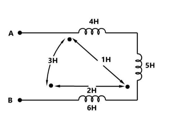
Sign in to UnlockThe effective inductance of the circuit across the terminals A, B in the fig, shown below is:
Sign in to see the solution
Log in to view the explanation, track your attempts, and keep your progress.
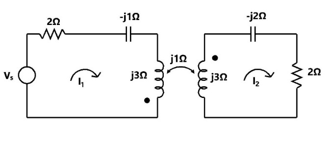
Sign in to UnlockDetermine the impedance seen by the source in the network shown in fig.

Sign in to see the solution
Log in to view the explanation, track your attempts, and keep your progress.
Sign in to UnlockTwo identical coils negligible resistance when connected in series across a 200V, 50Hz source draws, a current of 10A. When the terminals of one of the coils are reversed, then current drawn is 8A. The coefficient of coupling between the two coils is
Sign in to see the solution
Log in to view the explanation, track your attempts, and keep your progress.
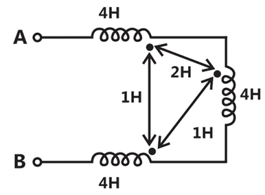
Sign in to UnlockThe equivalent inductance seen at terminals A-B in figure is _____________H
Sign in to see the solution
Log in to view the explanation, track your attempts, and keep your progress.
Sign in to Unlock