Network Analysis
Sinusoidal Steady State Analysis
Practice questions from Sinusoidal Steady State Analysis.
83
Total0
Attempted0
Correct0
IncorrectA single-phase voltage source delivers a current, A to a load.


The load power factor, correct up to two decimal places, is:
Sign in to see the solution
Log in to view the explanation, track your attempts, and keep your progress.
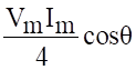
Sign in to UnlockAn electrical component has voltage drop , when the current through it is .
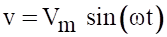
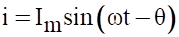
What is the average power dissipated over a half cycle corresponding to ?

0
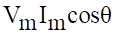
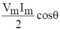
Sign in to see the solution
Log in to view the explanation, track your attempts, and keep your progress.
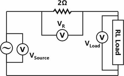
Sign in to UnlockIn an experiment to measure the active power drawn by a single-phase RL Load connected to an AC source through a resistor, three voltmeters are connected as shown in the figure below. The voltmeter readings are as follows: . Assuming perfect resistors and ideal voltmeters, the Load-active power measured in this experiment, in W, is __________ (round off to one decimal place).


Sign in to see the solution
Log in to view the explanation, track your attempts, and keep your progress.
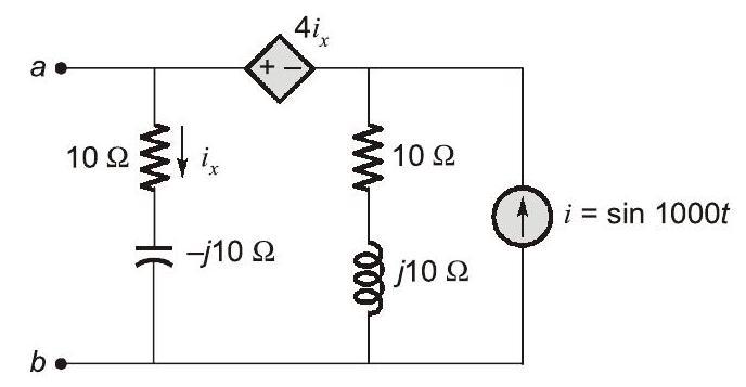
Sign in to UnlockFor the circuit shown, if , the instantaneous value of the Thevenin's equivalent voltage (in Volts) across the terminals at time is __________ (Round off to 2 decimal places).



Sign in to see the solution
Log in to view the explanation, track your attempts, and keep your progress.
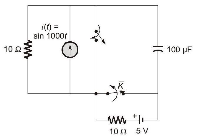
Sign in to UnlockThe circuit shown in the figure is initially in the steady state with the switch in open condition and in closed condition. The switch is closed and is opened simultaneously at the instant , where . The minimum value of in milliseconds, such that there is no transient in the voltage across the capacitor, is (Round off to 2 decimal places).






Sign in to see the solution
Log in to view the explanation, track your attempts, and keep your progress.
Sign in to UnlockAn inductor having a 𝑄-factor of 60 is connected in series with a capacitor having a 𝑄-factor of 240. The overall 𝑄-factor of the circuit is ________. (round off to nearest integer)
Sign in to see the solution
Log in to view the explanation, track your attempts, and keep your progress.
Sign in to UnlockThe network shown below has a resonant frequency of 150 kHz and a bandwidth of 600 Hz. The 𝑄-factor of the network is __________. (round off to nearest integer)
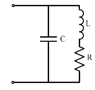
Sign in to see the solution
Log in to view the explanation, track your attempts, and keep your progress.
Sign in to UnlockIn the given circuit, the value of capacitor C that makes current I = 0 is _________ μF.
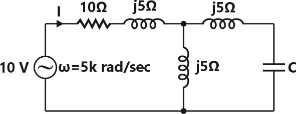
Sign in to see the solution
Log in to view the explanation, track your attempts, and keep your progress.
Sign in to UnlockIn the given circuit, for maximum power to be delivered to , its value should be …………… Ω. (Round off to 2 decimal places).

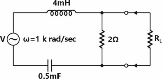
Sign in to see the solution
Log in to view the explanation, track your attempts, and keep your progress.
Sign in to UnlockCurrent through ammeters and in fig. are 1 ∠ 10° and 1 ∠ 70° respectively. The reading of the ammeter A1 (rounded off to 3 decimal places) is _________ A.


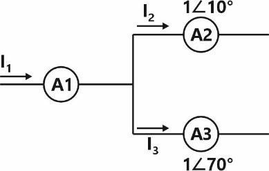
Sign in to see the solution
Log in to view the explanation, track your attempts, and keep your progress.
Sign in to UnlockThe voltage across and the current through a load are expressed as follows


The average power in watts (round off to one decimal place) consumed by the load is _______.
Sign in to see the solution
Log in to view the explanation, track your attempts, and keep your progress.
Sign in to UnlockIn the figure, the voltages are , and


. The circuit is in sinusoidal steady state, and, and are the average power outputs. Which one of the following statements is true?









Sign in to see the solution
Log in to view the explanation, track your attempts, and keep your progress.
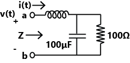
Sign in to UnlockThe voltage v(t) across the terminals a and b as shown in the figure, is a sinusoidal voltage having a frequency . When the inductor current i(t) is in phase with the voltage v(t), the magnitude of the impedance Z (in ) seen between the terminals a and is _______ (up to 2 decimal places).


Sign in to see the solution
Log in to view the explanation, track your attempts, and keep your progress.
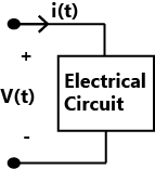
Sign in to UnlockThe voltage across the circuit in the figure, and the current through it are given by the following expressions:


Where , If the average power delivered to the circuit is zero then the value of X (in Ampere) is ________ (up to 2 decimal places).

Sign in to see the solution
Log in to view the explanation, track your attempts, and keep your progress.
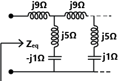
Sign in to UnlockThe equivalent impedance for the infinite ladder circuit shown in the figure is





Sign in to see the solution
Log in to view the explanation, track your attempts, and keep your progress.
Sign in to UnlockA source is supplying a load through a 2-phase, 3-wire transmission system as shown in figure below. The instantaneous voltage and current in phase-a are V and A, respectively. Similarly for phase-b, the instantaneous voltage and current are A, respectively.



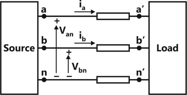
The total instantaneous power flowing from the source to the load is
2200 W

4400 W

Sign in to see the solution
Log in to view the explanation, track your attempts, and keep your progress.
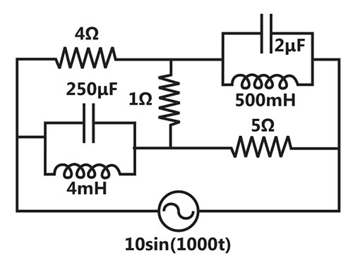
Sign in to UnlockIn the circuit shown below, the supply voltage is volts. The peak value of the steady state current through the resistor, in amperes, is _________________.


Sign in to see the solution
Log in to view the explanation, track your attempts, and keep your progress.
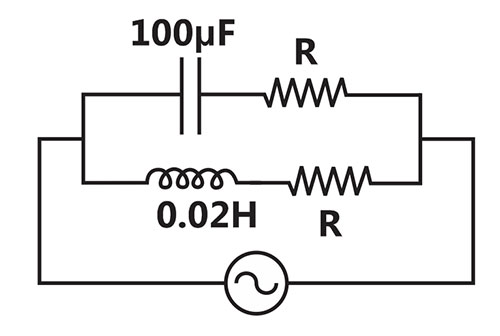
Sign in to UnlockThe circuit below is excited by a sinusoidal source. The value of R, in , for which the admittance of the circuit becomes a pure conductance at all frequencies is _____________.

Sign in to see the solution
Log in to view the explanation, track your attempts, and keep your progress.
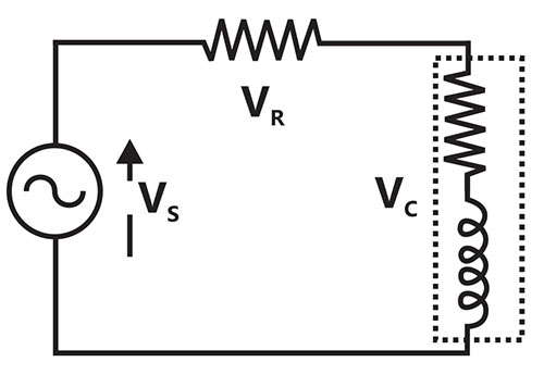
Sign in to UnlockA resistance and a coil connected in series and supplied from a phase, 100V, 50Hz ac source as shown in the figure below. The rms values of possible voltages across the resistance and coil respectively, in volts are


`
Sign in to see the solution
Log in to view the explanation, track your attempts, and keep your progress.
Sign in to UnlockThe voltage (V) and current ((A) across a load are as follows.
.

.

The average power consumed by the load, in W, is_____________.
Sign in to see the solution
Log in to view the explanation, track your attempts, and keep your progress.
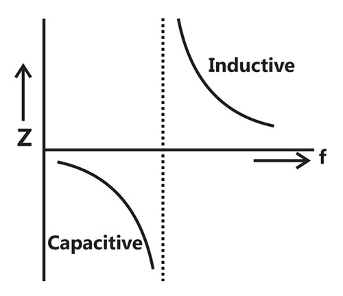
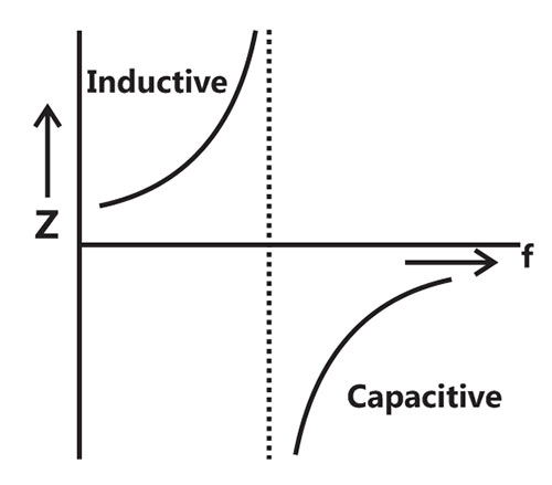
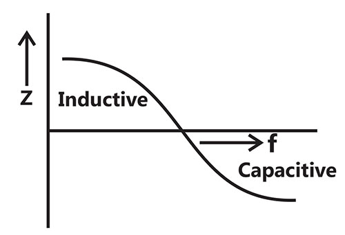
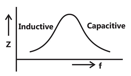
Sign in to UnlockAn inductor is connected in parallel with a capacitor as shown in the figure.
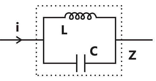
As the frequency of current i is increased, the impedance (Z) of the network varies as
Sign in to see the solution
Log in to view the explanation, track your attempts, and keep your progress.
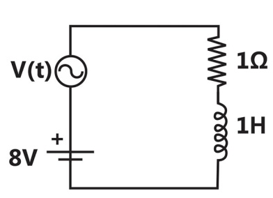
Sign in to UnlockThe circuit shown in the figure has two sources connected in series. The instantaneous voltage of the AC source (in Volt) is given by . If the circuit is in steady state, then the RMS value of the current (in Ampere) flowing in the circuit is

Sign in to see the solution
Log in to view the explanation, track your attempts, and keep your progress.
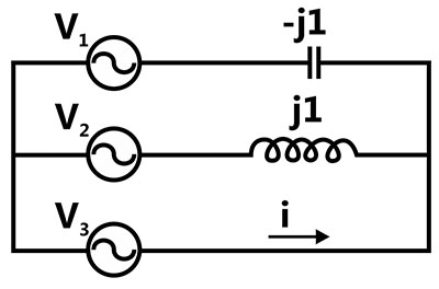
Sign in to UnlockIn the given network. , ,



The phasor current i (in Ampere) is




Sign in to see the solution
Log in to view the explanation, track your attempts, and keep your progress.
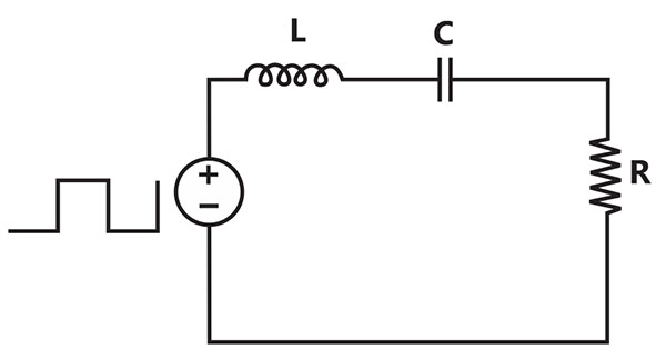
Sign in to UnlockA symmetrical square wave of 50% duty cycle has amplitude of ±15V and time period of . This square wave is applied across a series RLC circuit with L=10mH and . The amplitude of the 5000 rad/s component of the capacitor voltage (in volt) is ____________.



Sign in to see the solution
Log in to view the explanation, track your attempts, and keep your progress.
Sign in to UnlockThe voltage across the capacitor, as shown in the figure, is expressed as +


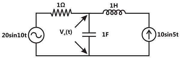
The values of and respectively, are


Sign in to see the solution
Log in to view the explanation, track your attempts, and keep your progress.
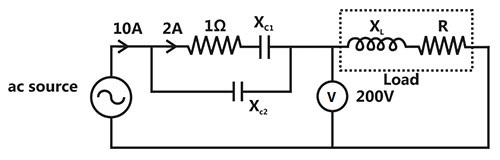
Sign in to UnlockThe total power dissipated in the circuit, shown in the figure, is 1kW. The voltmeter, across the load, reads 200V. The value of is ____________

Sign in to see the solution
Log in to view the explanation, track your attempts, and keep your progress.
Sign in to UnlockA series RLC circuit is observed at two frequencies. At , we note that source voltage results in a current . At , the source voltage results in a current . The closest values for R, L, C out of the following options are









Sign in to see the solution
Log in to view the explanation, track your attempts, and keep your progress.
Sign in to UnlockA single-phase load is supplied by a single –phase voltage source. If the current flowing from the Load to the source is and if the voltage at the load terminals is , then the


Sign in to see the solution
Log in to view the explanation, track your attempts, and keep your progress.
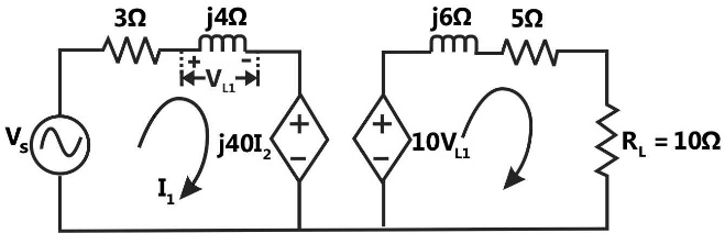
Sign in to UnlockIn the circuit shown below, if the source voltage then the Thevenin’s equivalent voltage in volts as seen by the load resistance is






Sign in to see the solution
Log in to view the explanation, track your attempts, and keep your progress.
Sign in to UnlockTwo magnetically uncoupled inductive coils have Q factors and at the chosen operating frequency. Their respective resistances are and . When connected in series, their effective Q factor at the same operating frequency is








Sign in to see the solution
Log in to view the explanation, track your attempts, and keep your progress.
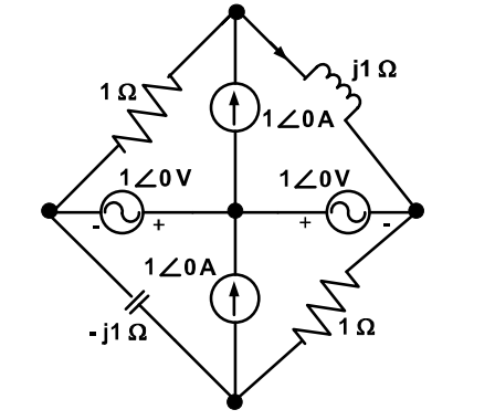
Sign in to UnlockIn the circuit shown below, the current through the inductor is



0 A
Sign in to see the solution
Log in to view the explanation, track your attempts, and keep your progress.
Sign in to UnlockThe average power delivered to an impedance (4–j3) by a current is

Sign in to see the solution
Log in to view the explanation, track your attempts, and keep your progress.
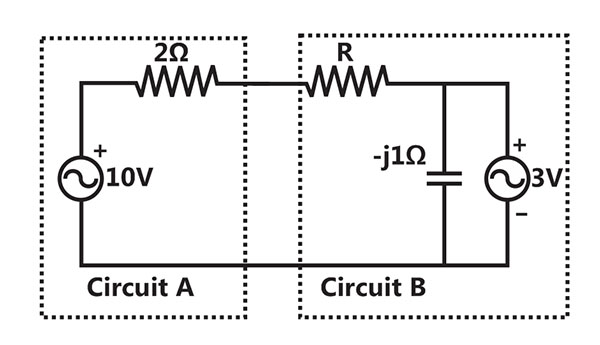
Sign in to UnlockAssuming both the voltage sources are in phase, the value of R for which maximum power is transferred from circuit A to circuit B is




Sign in to see the solution
Log in to view the explanation, track your attempts, and keep your progress.
Sign in to Unlock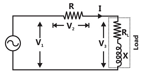
In the circuit shown, the three voltmeter readings are .

The power factor of the load is
Sign in to see the solution
Log in to view the explanation, track your attempts, and keep your progress.
Sign in to UnlockIn the circuit shown, the three voltmeter readings are .
If , the approximate power consumption in the load is

Sign in to see the solution
Log in to view the explanation, track your attempts, and keep your progress.
Sign in to UnlockThe RMS value of the current i(t) in the circuit shown below is
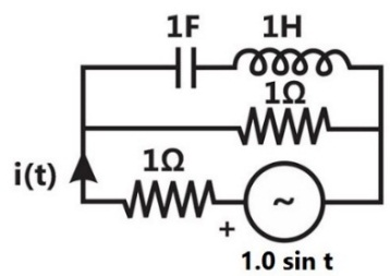


1A

Sign in to see the solution
Log in to view the explanation, track your attempts, and keep your progress.
Sign in to UnlockThe voltage applied to a circuit is volts and the circuit draws a current of amperes. Taking the voltage as the reference phasor, the phasor representation of the current in amperes is






Sign in to see the solution
Log in to view the explanation, track your attempts, and keep your progress.
Sign in to UnlockAn RLC circuit with relevant data is given below.
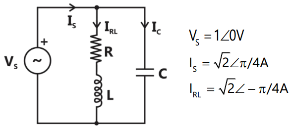
The power dissipated in the resistor R is
0.5W
1W

2W
Sign in to see the solution
Log in to view the explanation, track your attempts, and keep your progress.
Sign in to UnlockAn RLC circuit with relevant data is given below.
The current in the figure above is

–j 2A


+j2 A
Sign in to see the solution
Log in to view the explanation, track your attempts, and keep your progress.
Sign in to UnlockThe equivalent capacitance of the input loop of the circuit shown is
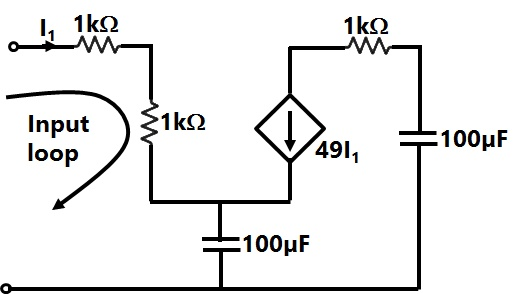
Sign in to see the solution
Log in to view the explanation, track your attempts, and keep your progress.
Sign in to UnlockThe Thevenin's equivalent of a circuit operating at, has and . At this frequency, the minimal realization of the Thevenin's impedance will have a



Sign in to see the solution
Log in to view the explanation, track your attempts, and keep your progress.
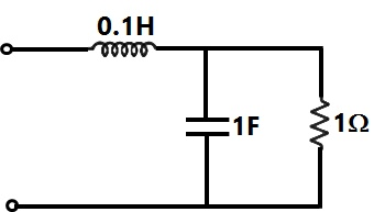
Sign in to UnlockThe resonant frequency for the given circuit will be
Sign in to see the solution
Log in to view the explanation, track your attempts, and keep your progress.
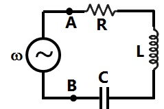
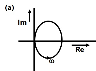
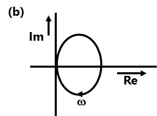
Sign in to UnlockThe R-L-C series circuit shown is supplied from a variable frequency voltage source. The admittance-locus of the R-L-C network at terminals AB for increasing frequency ω is
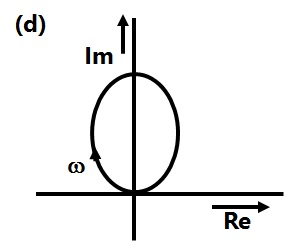
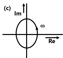
Sign in to see the solution
Log in to view the explanation, track your attempts, and keep your progress.
Sign in to UnlockIn the figure given below all phasors are with reference to the potential at point "O". The locus of voltage phasor as R is varied from zero to infinity is shown by

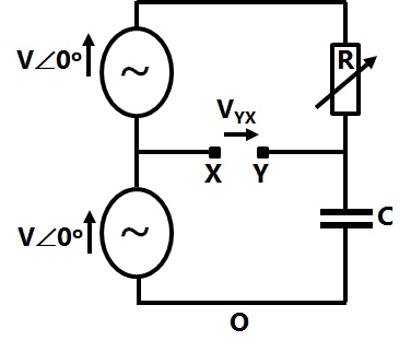
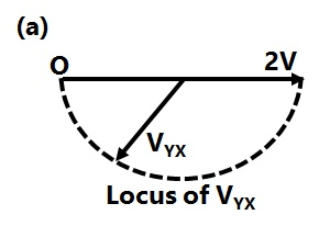
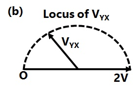
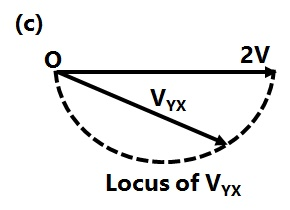
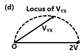
Sign in to see the solution
Log in to view the explanation, track your attempts, and keep your progress.
Sign in to UnlockAn energy meter connected to an immersion heater (resistive) operating on an AC 230 V, 50 Hz, AC single phase source reads 2.3 units (kWh) in 1 hour. The heater is removed from the supply and now connected to a 400 V peak square wave source of 150 Hz. The power in kW dissipated by the heater will be
Sign in to see the solution
Log in to view the explanation, track your attempts, and keep your progress.
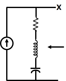
Sign in to UnlockIn the figure the current source is 1∠0 A, R=1Ω, the impedances are , and . The Thevenin equivalent looking into the circuit across X-Y is






Sign in to see the solution
Log in to view the explanation, track your attempts, and keep your progress.
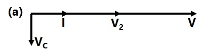
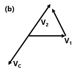
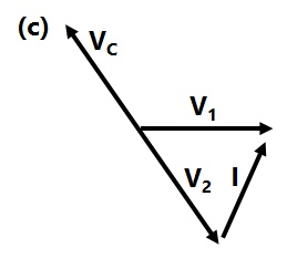
Sign in to UnlockThe circuit shown in the figure is energized by a sinusoidal voltage source at a frequency which causes resonance with a current of I.

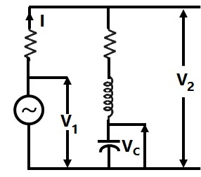
The phasor diagram which is applicable to this circuit is
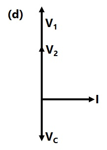
Sign in to see the solution
Log in to view the explanation, track your attempts, and keep your progress.
Sign in to UnlockThe RMS value of the voltage is:


5V
7V

Sign in to see the solution
Log in to view the explanation, track your attempts, and keep your progress.
Sign in to UnlockThe RL circuit of Figure is fed from a constant magnitude, variable frequency sinusoidal voltage source . At 100 Hz, the R and L elements each have a voltage drop . If the frequency of the source is changed to 50 Hz, the new voltage drop across R is:


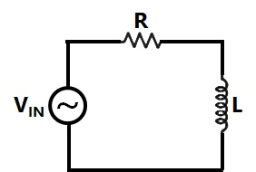




Sign in to see the solution
Log in to view the explanation, track your attempts, and keep your progress.
Sign in to UnlockIn the figure the value of Z in Figure, which is most appropriate to cause parallel resonance at 500 Hz, is
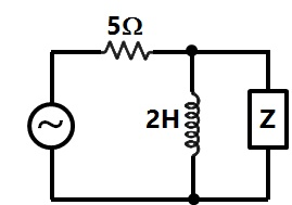
Sign in to see the solution
Log in to view the explanation, track your attempts, and keep your progress.
Sign in to UnlockTotal instantaneous power supplied by a 3-phase ac supply to a balanced R-L load is
Sign in to see the solution
Log in to view the explanation, track your attempts, and keep your progress.
Sign in to UnlockIn figure, the admittance values of the elements in Siemens are
respectively.

The value of I as a phasor when the voltage E across the elements isis

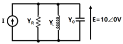
Sign in to see the solution
Log in to view the explanation, track your attempts, and keep your progress.
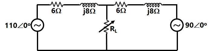
Sign in to UnlockTwo ac sources feed a common variable resistive load as shown in Figure. Under the maximum power transfer condition, the power absorbed by the load resistance RL is
Sign in to see the solution
Log in to view the explanation, track your attempts, and keep your progress.
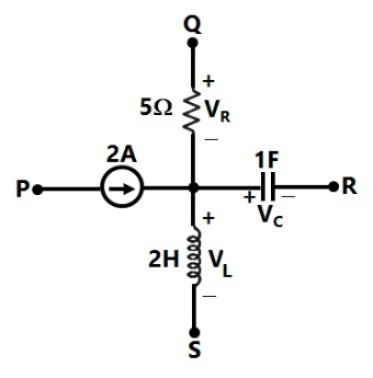
Sign in to UnlockA segment of a circuit is shown in Figure. , . The voltage is given by



Sign in to see the solution
Log in to view the explanation, track your attempts, and keep your progress.
Sign in to UnlockIn the Figure.
.
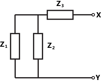

The thevenin impedance seen from X-Y is
Sign in to see the solution
Log in to view the explanation, track your attempts, and keep your progress.
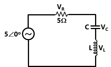
Sign in to UnlockIn the circuit of Figure, the magnitudes of and are twice that of . The inductance of the coil is


Sign in to see the solution
Log in to view the explanation, track your attempts, and keep your progress.
Sign in to UnlockIn the circuit shown in Figure, what value of C will cause a unity power factor at the ac source?
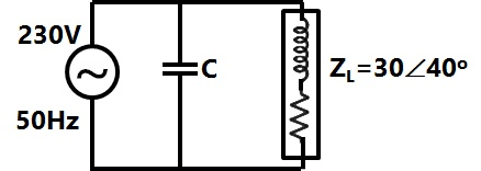
Sign in to see the solution
Log in to view the explanation, track your attempts, and keep your progress.
Sign in to UnlockA series R-L-C circuit has R = 50Ω, L = 100 μH and C = 1 μF. the lower half power frequency of the circuit is
Sign in to see the solution
Log in to view the explanation, track your attempts, and keep your progress.
Sign in to UnlockConsider the circuit shown in Figure. If the frequency of the source is 50 Hz, then a value of which results in a transient free response is

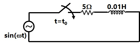
Sign in to see the solution
Log in to view the explanation, track your attempts, and keep your progress.
Sign in to UnlockAn electrical network is fed by two ac sources, as shown Figure. Given that , and . Obtain the Thevenin equivalent circuit (Thevenin voltage and impedance) across terminals x and y, and determine the current through the load .





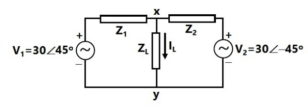
Sign in to see the solution
Log in to view the explanation, track your attempts, and keep your progress.
Sign in to UnlockIn a series RLC circuit at resonance, the magnitude of the voltage developed across the capacitor.
Sign in to see the solution
Log in to view the explanation, track your attempts, and keep your progress.
Sign in to UnlockA 240 V single-phase ac source is connected to a load with an impedance of . A capacitor is connected in parallel with the load. If the capacitor supplied 1250 VAR, the real power supplied by the source is

Sign in to see the solution
Log in to view the explanation, track your attempts, and keep your progress.
Sign in to UnlockDetermine the resonance frequency and the Q-factor of the circuit shown in figure.
Data: R = 10Ω, C = 3µF, , and M = 10 mH.


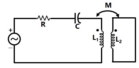
Sign in to see the solution
Log in to view the explanation, track your attempts, and keep your progress.
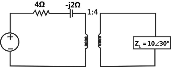
Sign in to UnlockThe impedance seen by the source in the circuit in figure, is given by




Sign in to see the solution
Log in to view the explanation, track your attempts, and keep your progress.
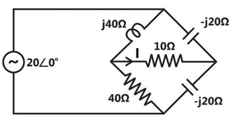
Sign in to UnlockPredict the current I in figure in response to a voltage of . The impedance values are given in ohms. Use the thevenin’s theorem.

Sign in to see the solution
Log in to view the explanation, track your attempts, and keep your progress.
Sign in to UnlockA series R-L-C circuit when excited by a 10V sinusoidal voltage source of variable frequency, exhibits resonance at 100Hz and has a 3 dB bandwidth of 5Hz. The voltage across the inductor L at resonance is:
10V


200V
Sign in to see the solution
Log in to view the explanation, track your attempts, and keep your progress.
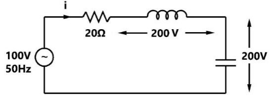
Sign in to UnlockThe current in the circuit shown in figure is:
Sign in to see the solution
Log in to view the explanation, track your attempts, and keep your progress.
Sign in to UnlockCurrents , and meet at a junction (node) in a circuit. All currents are marked as entering the node.



If and , then will be







Sign in to see the solution
Log in to view the explanation, track your attempts, and keep your progress.
Sign in to UnlockA fixed capacitor of reactance –j0.02 kΩ is connected in parallel across a series combination of a fixed inductor of reactance j0.01 kΩ and a variable resistance R. As R is varied from zero to infinity, the locus diagram of the admittance of this L-C-R circuit will be
Sign in to see the solution
Log in to view the explanation, track your attempts, and keep your progress.
Sign in to UnlockThe voltage phasor of a circuit is and the current phasor is A. The active and the reactive powers in the circuit are:


10W and 17.32 VAr
5W and 8.66 VAr
20W and 60 VAr
and


Sign in to see the solution
Log in to view the explanation, track your attempts, and keep your progress.
Sign in to UnlockA constant voltage frequency sinusoidal voltage source of magnitude is connected to a series circuit made of a resistance of 15Ω, a coil of winding resistance R and inductance L and a 50μF capacitor. The voltage across the 15Ω resistors is 30V, across the coil is 50V, across the capacitor is 40V, The voltage across the combination of the 15Ω resistor and the coil together is 72.11V. Determine the values of the inductance L, winding resistance R and the source voltage V.

Sign in to see the solution
Log in to view the explanation, track your attempts, and keep your progress.
Sign in to UnlockA sinusoidal source of voltage V and frequency f is connected to a series circuit of variable resistance, R and a fixed reactance, X. the locus of the tip of the current-phasor I, as R is varied from 0 to ∞ is:
A semicircle with a diameter of

A straight line with a slop of

An ellipse with as major axis

A circle of radius and origin at


Sign in to see the solution
Log in to view the explanation, track your attempts, and keep your progress.
Sign in to UnlockA circuit with a resistor, inductor and capacitor in series is resonant of If all the component values are now doubled, the new resonant frequency is:


still



Sign in to see the solution
Log in to view the explanation, track your attempts, and keep your progress.
Sign in to UnlockA water boiler at home is switched on the a.c. mains supplying power at 230V/50Hz. The frequency of instantaneous power consumed by the boiler is
Sign in to see the solution
Log in to view the explanation, track your attempts, and keep your progress.
Sign in to UnlockA coil (which can be modeled as a series RL circuit) has been designed for high-Q performance at a rated voltage and a specified frequency. If the frequency of operation is doubled, and the coil is operated at the same rated voltage, then the Q-factor and the active power P consumed by the coil will be affected as follows
Sign in to see the solution
Log in to view the explanation, track your attempts, and keep your progress.
Sign in to UnlockA series R-L-C circuit has the following parameter values: , , .The Q factor of the circuit at resonance is __________



Sign in to see the solution
Log in to view the explanation, track your attempts, and keep your progress.
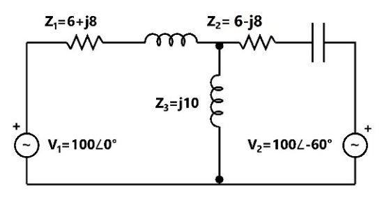
Sign in to UnlockIn the network system shown in figure, find the current through using nodal method. The values of voltages are given in volts and the impedances are given in ohms.





Sign in to see the solution
Log in to view the explanation, track your attempts, and keep your progress.
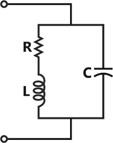
Sign in to UnlockAt resonance, the given parallel circuit constituted by an iron-coil and a capacitor behaves like
Sign in to see the solution
Log in to view the explanation, track your attempts, and keep your progress.
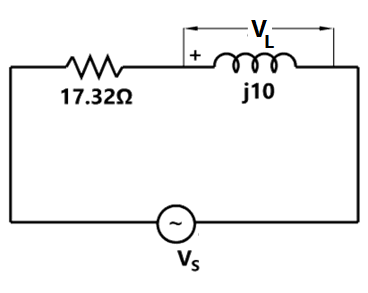
Sign in to UnlockIn the given circuit, the voltage , has a phase angle of _____________ with respect to .


Sign in to see the solution
Log in to view the explanation, track your attempts, and keep your progress.
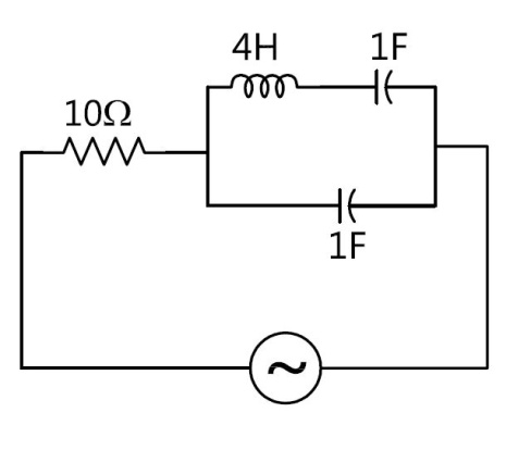
Sign in to UnlockThe following circuit (figure) resonates at
Sign in to see the solution
Log in to view the explanation, track your attempts, and keep your progress.
Sign in to UnlockIn the figure shown, are ideal ammeters. If read 5 and 13A respectively, reading of will be


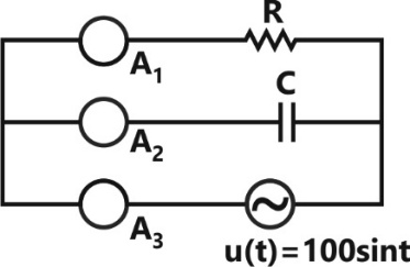
8A
12A
18A
Indeterminate unless the actual values of R, C and are specified

Sign in to see the solution
Log in to view the explanation, track your attempts, and keep your progress.
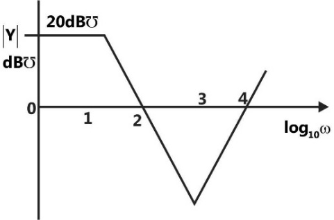
Sign in to UnlockA one port active network has an input admittance Y, the magnitude of which is shown in figure as a function of frequency. The circuit is resistive or capacitive in different frequency ranges.
Complete the following table:
Frequency Range | Type of Impedance | Value (Ω/H/F) |
10000 rad/sec < ω | A | P |
10 rad/sec < ω < 1000 rad/sec | B | Q |
Sign in to see the solution
Log in to view the explanation, track your attempts, and keep your progress.
Sign in to UnlockIn figure calculate
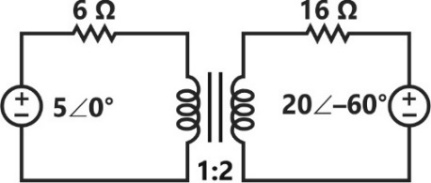
(a) The power delivered by each source
(b) The power dissipated in each resistor
Sign in to see the solution
Log in to view the explanation, track your attempts, and keep your progress.
Sign in to Unlock