Control Systems
Transfer Function
Practice questions from Transfer Function.
28
Total0
Attempted0
Correct0
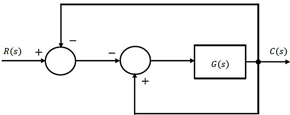
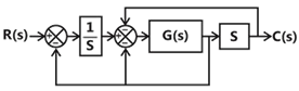
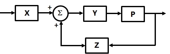
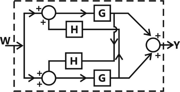
IncorrectFor the block-diagram shown in the figure, the transfer function is


Sign in to see the solution
Log in to view the explanation, track your attempts, and keep your progress.
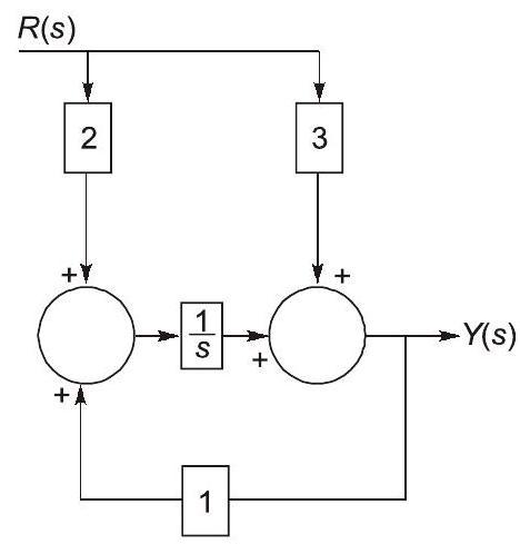
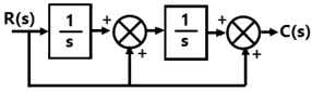
Sign in to UnlockFor the block diagram shown in the figure, the transfer function is


Sign in to see the solution
Log in to view the explanation, track your attempts, and keep your progress.
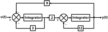
Sign in to UnlockA continuous-time system that is initially at rest is described by

where is the input voltage and is the output voltage. The impulse response of the system is


Sign in to see the solution
Log in to view the explanation, track your attempts, and keep your progress.
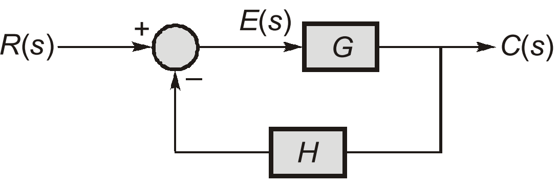
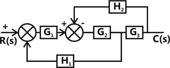
Sign in to UnlockFor the closed-loop system shown, the transfer function is


Sign in to see the solution
Log in to view the explanation, track your attempts, and keep your progress.
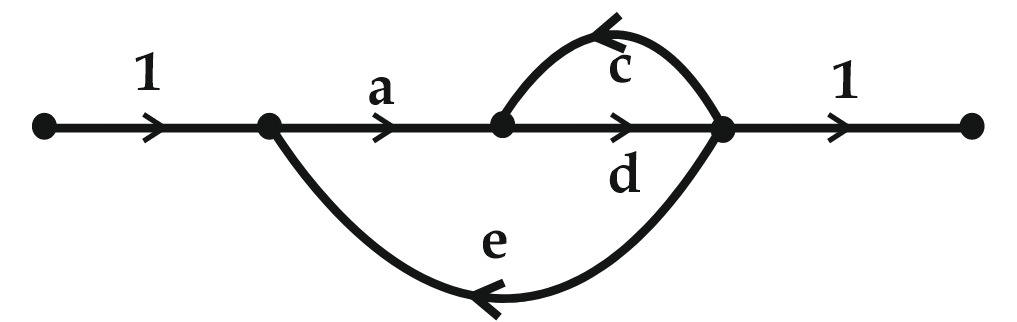
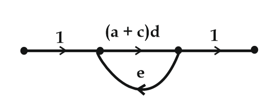
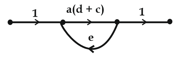
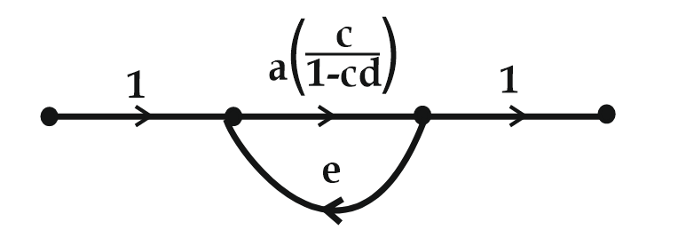
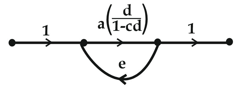
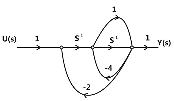
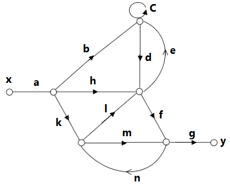
Sign in to UnlockWhich of the options is an equivalent representation of the signal flow graph shown here?
Sign in to see the solution
Log in to view the explanation, track your attempts, and keep your progress.
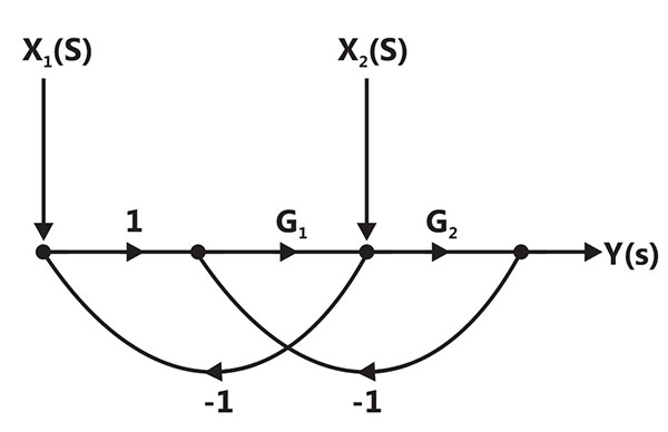
Sign in to UnlockIn the system whose signal flow graph is shown in the figure, are inputs. The transfer function v


Sign in to see the solution
Log in to view the explanation, track your attempts, and keep your progress.
Sign in to UnlockFor the signal – flow graph shown in the figure, which one of the following expressions is equal to the transfer function


Sign in to see the solution
Log in to view the explanation, track your attempts, and keep your progress.
Sign in to UnlockFind the transfer function of the system given below.


Sign in to see the solution
Log in to view the explanation, track your attempts, and keep your progress.
Sign in to UnlockThe signal flow graph of a system is shown below. U(s) is the input and C(s) is the output.
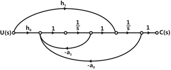
Assuming, , the input-output transfer function, of the system is given by


Sign in to see the solution
Log in to view the explanation, track your attempts, and keep your progress.
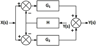
Sign in to UnlockThe block diagram of a system is shown in the figure
If the desired transfer function of the system is

Then G(s) is

s
1/s
This cannot be expressed in the required form for any value of G(s)
Sign in to see the solution
Log in to view the explanation, track your attempts, and keep your progress.
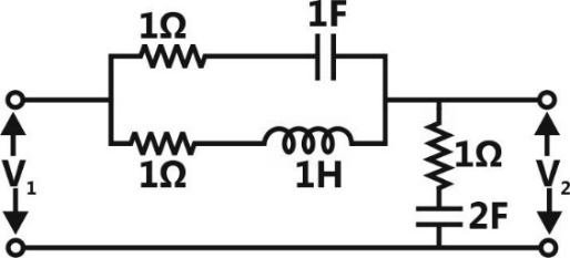
Sign in to UnlockThe transfer function of the circuit shown below is


Sign in to see the solution
Log in to view the explanation, track your attempts, and keep your progress.
Sign in to UnlockThe signal flow graph for a system is given below. The transfer function for this system is


Sign in to see the solution
Log in to view the explanation, track your attempts, and keep your progress.
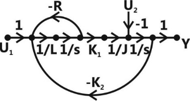
Sign in to UnlockA two-loop position control system is shown below.
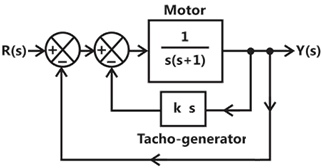
The gain k of the Tacho-generator influences mainly the
Peak overshoot
Natural frequency of oscillations
Phase shift of the closed loop transfer function at very low frequencies

Phase shift of the closed loop transfer function at very high frequencies

Sign in to see the solution
Log in to view the explanation, track your attempts, and keep your progress.
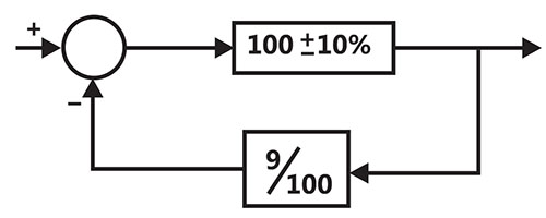
Sign in to UnlockAs shown in the figure, a negative feedback system has an amplifier of gain 100 with ±10% tolerance in the forward path, and an attenuator of value 9/100 in the feedback path. The overall system gain is approximately:
Sign in to see the solution
Log in to view the explanation, track your attempts, and keep your progress.
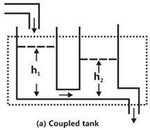
Sign in to UnlockIf the electrical circuit of figure (b) is an equivalent of the coupled tank system of figure (a). then
Sign in to see the solution
Log in to view the explanation, track your attempts, and keep your progress.
Sign in to UnlockThe system shown in figure below,
Can be reduced to the form
With


Sign in to see the solution
Log in to view the explanation, track your attempts, and keep your progress.
Sign in to UnlockFor a tachometer if θ(t) is the rotor displacement is radians, e(t) is the output voltage and Kt is the tachometer constant in V/rad/sec, then the transfer function, will be


Sign in to see the solution
Log in to view the explanation, track your attempts, and keep your progress.
Sign in to UnlockFor the block diagram shown in figure, the transfer function is equal to


Sign in to see the solution
Log in to view the explanation, track your attempts, and keep your progress.
Sign in to UnlockThe block diagram of a control system is shown in Figure. The transfer function of the system is


Sign in to see the solution
Log in to view the explanation, track your attempts, and keep your progress.
Sign in to UnlockThe transfer function of the system described by with u as input and y as output is


Sign in to see the solution
Log in to view the explanation, track your attempts, and keep your progress.
Sign in to UnlockRatio of the rotor reactance X to the rotor resistance R for a two-phase servomotor
Sign in to see the solution
Log in to view the explanation, track your attempts, and keep your progress.
Sign in to UnlockFeedback control systems are
Sign in to see the solution
Log in to view the explanation, track your attempts, and keep your progress.
Sign in to UnlockFor block diagram shown in fig. is given by


Sign in to see the solution
Log in to view the explanation, track your attempts, and keep your progress.
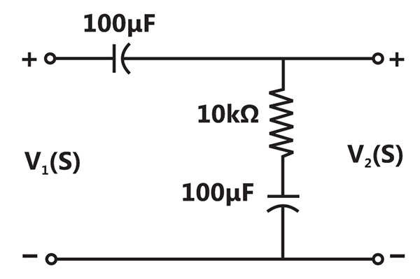
Sign in to UnlockFor the circuit shown in figure, the transfer function is equal to ?
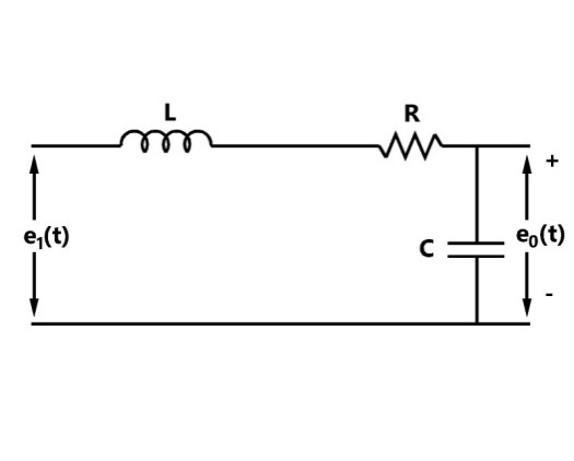
None of these
Sign in to see the solution
Log in to view the explanation, track your attempts, and keep your progress.
Sign in to UnlockSignal flow graph is used to obtain the
Sign in to see the solution
Log in to view the explanation, track your attempts, and keep your progress.
Sign in to UnlockThe overall transfer function of the system in figure, is


Sign in to see the solution
Log in to view the explanation, track your attempts, and keep your progress.
Sign in to UnlockThe signal flow graph of figure has ____________ forward paths/and ____________ feedback loops.
Sign in to see the solution
Log in to view the explanation, track your attempts, and keep your progress.
Sign in to Unlock(a) Find the transfer function
for the network shown in figure.

(b) What is the order of the system?
(c) Now if the inductance value is changed to 2H, what will be the order of the modified network?
order of the system = 1

order of the system = 2
order of the modified network = 3
Sign in to see the solution
Log in to view the explanation, track your attempts, and keep your progress.
Sign in to Unlock