Digital Electronics
Data Converters
Practice questions from Data Converters.
22
Total0
Attempted0
Correct0
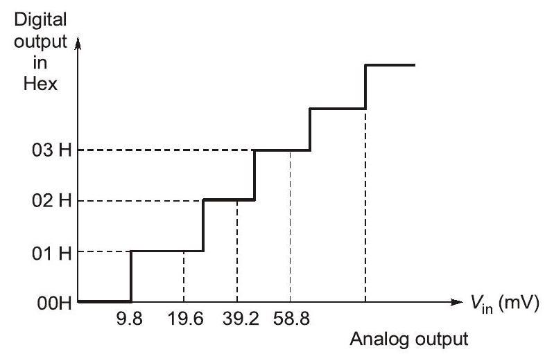
IncorrectAn 8-bit ADC converts analog voltage in the range of 0 to to the corresponding digital code as per the conversion characteristics shown in figure. For , which of the following digital output, given in hex, is true?


Sign in to see the solution
Log in to view the explanation, track your attempts, and keep your progress.
Sign in to UnlockA temperature in the range of is to be measured with a resolution of . The minimum number of ADC bits required to get a matching dynamic range of the temperature sensor is


Sign in to see the solution
Log in to view the explanation, track your attempts, and keep your progress.
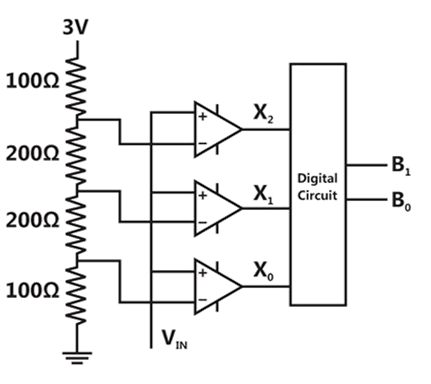
Sign in to UnlockA 2-bit flash Analog to digital converter (ADC) is given below. The input is Volts. The expression for the LSB of the output as a Boolean function of and is


Sign in to see the solution
Log in to view the explanation, track your attempts, and keep your progress.
Sign in to UnlockAn 8-bit, unipolar successive approximation register type ADC is used to convert 3.5V to digital equivalent output. The reference voltage is +5V. The output of the ADC, at the end of 3rd clock pulse after the start of conversion, is
Sign in to see the solution
Log in to view the explanation, track your attempts, and keep your progress.
Sign in to UnlockTwo 8-bit ADCs, one of single slope integrating type and other of successive approximation type, take and times to convert 5V analog input signal to equivalent digital output. If the input analog signal is reduced to 2.5V, the approximate lime taken by the two ADCs will respectively be


Sign in to see the solution
Log in to view the explanation, track your attempts, and keep your progress.
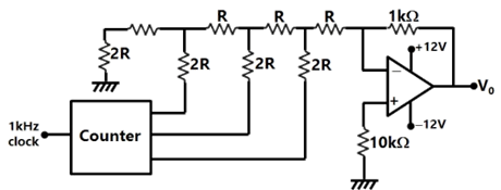
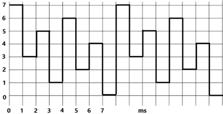
Sign in to UnlockA student has made a 3-bit binary down counter and connected to the R- 2R ladder type DAC [Gain = (-1 kΩ/2R)] as shown in figure to generate a staircase waveform. The output achieved is different as shown in figure. What could be the possible cause of this error?
Sign in to see the solution
Log in to view the explanation, track your attempts, and keep your progress.
Sign in to UnlockIt is required to design an anti-aliasing filter for an 8 bit ADC. The filter is a first order RC filter with R = 1Ω and C = 1F. The ADC is designed to span a sinusoidal signal with peak to peak amplitude equal to the full range of the ADC.
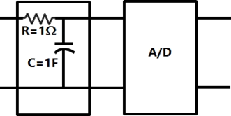
The transfer function of the filter and its roll off respectively are
dB/decade

dB/decade

dB/decade

dB/decade

Sign in to see the solution
Log in to view the explanation, track your attempts, and keep your progress.
Sign in to UnlockIt is required to design an anti-aliasing filter for an 8 bit ADC. The filter is a first order RC filter with R = 1W and C = 1F. The ADC is designed to span a sinusoidal signal with peak to peak amplitude equal to the full range of the ADC.

What is the SNR (in dB) of the ADC? Also find the frequency (in decades) at the filter output at which the filter attenuation just exceeds the SNR of the ADC.
Sign in to see the solution
Log in to view the explanation, track your attempts, and keep your progress.
Sign in to UnlockA digital-to-analog converter with a full-scale output voltage of 3.5V has a resolution close to 14 mV. Its bit size is:
Sign in to see the solution
Log in to view the explanation, track your attempts, and keep your progress.
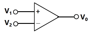
Sign in to UnlockThe voltage comparator shown in figure can be used in as
Sign in to see the solution
Log in to view the explanation, track your attempts, and keep your progress.
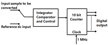
Sign in to UnlockThe simplified block diagram of a 10-bit A/D converter of dual slope integrator type is shown in figure. The 10-bit counter at the output is clocked by a 1MHz clock. Assuming negligible timing overhead for the control logic, the maximum frequency of the analog signal that can be converted using this A/D converter is approximately
Sign in to see the solution
Log in to view the explanation, track your attempts, and keep your progress.
Sign in to UnlockAmong the following four, the slowest ADC (analog-to-digital converter) is
Sign in to see the solution
Log in to view the explanation, track your attempts, and keep your progress.
Sign in to UnlockA sample-and-hold (S/H) circuit, having a holding capacitor of 0.1nF, is used at the input of an ADC (analog-to-digital converter). The conversion time of the ADC is 1µsec, and during this time, the capacitor should not lose more than 0.5% of the charge put across it during the sampling time. The maximum value of the input signal to the S/H circuit is 5V. The leakage current of the S/H circuit should be less than
Sign in to see the solution
Log in to view the explanation, track your attempts, and keep your progress.
Sign in to UnlockA dual slope analog-to-digit converters uses an N-bit counter. When the input signal is being integrated, the counter is allowed to count up to a value


Equal to
Equal to

Proportional to
Inversely proportional to
Sign in to see the solution
Log in to view the explanation, track your attempts, and keep your progress.
Sign in to UnlockA single channel digital storage oscilloscope uses a 10 bit, samples per second Analog-to-Digital converter. For a 100 KHz sine wave input, the number of samples taken per cycle of the input will be


Sign in to see the solution
Log in to view the explanation, track your attempts, and keep your progress.
Sign in to UnlockFor a dual ADC type digit DVM, the reference voltage is 100mV and the first integration time is set to 300ms. For some input voltage, the “de-integration” period is 370.2ms. The DVM will indicate

Sign in to see the solution
Log in to view the explanation, track your attempts, and keep your progress.
Sign in to UnlockA digit, 2 V full scale slope ADC has its integration time set to 300ms. If the input to the ADC is (1+1sin314t)V, then the ADC output will be

Sign in to see the solution
Log in to view the explanation, track your attempts, and keep your progress.
Sign in to UnlockThe number of comparisons carried out in a 4-bit flash-type A/D converter is_________?
Sign in to see the solution
Log in to view the explanation, track your attempts, and keep your progress.
Sign in to UnlockA 10 bit A/D converter is used to digitize an analog signal in the 0 to 5V range. The maximum peak to peak ripple voltage that can be allowed in the D.C. supply voltage is
Sign in to see the solution
Log in to view the explanation, track your attempts, and keep your progress.
Sign in to UnlockThe number of comparators needed in a parallel conversion type 8-bit A to D converter is
Sign in to see the solution
Log in to view the explanation, track your attempts, and keep your progress.
Sign in to UnlockIn a dual slope integrating type digital voltmeter the first integration is carried out for 10 periods of the supply frequency of 50 Hz. If the reference voltage used is 2 V, the total conversion time for an input 1V is ___________ sec
Sign in to see the solution
Log in to view the explanation, track your attempts, and keep your progress.
Sign in to UnlockThe resolution of an 8-bit A/D converter is ________________%
Sign in to see the solution
Log in to view the explanation, track your attempts, and keep your progress.
Sign in to Unlock