Network Analysis
Network Basics
Practice questions from Network Basics.
60
Total0
Attempted0
Correct0
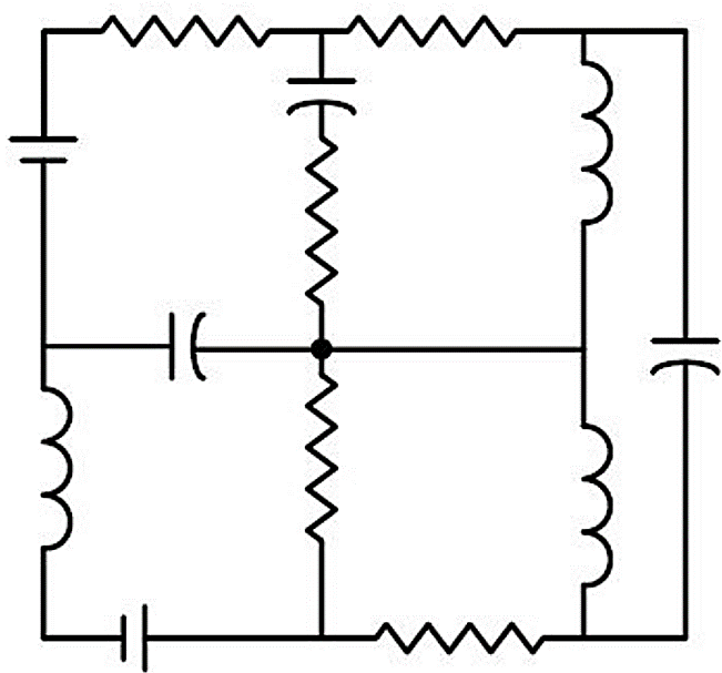
IncorrectA circuit with ideal elements is shown.
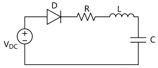
Which one of the following options correctly identifies all the linear elements in the circuit?
Sign in to see the solution
Log in to view the explanation, track your attempts, and keep your progress.
Sign in to UnlockRefer to the four circuits shown.
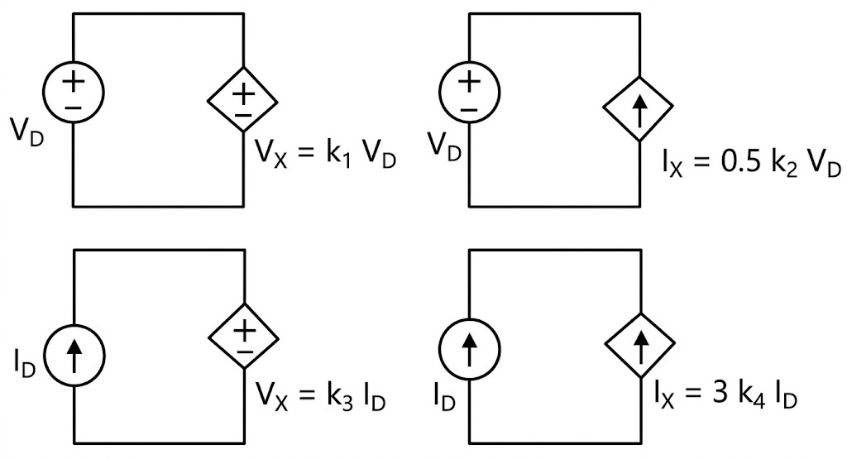
Which one of the following options for , and makes all of them realizable?


, for all values of and


, for all values of and


Sign in to see the solution
Log in to view the explanation, track your attempts, and keep your progress.
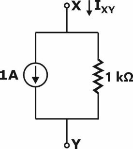
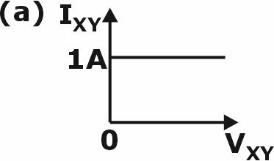
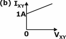
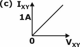
Sign in to UnlockThe I-V characteristics of the element between the nodes X and Y is best depicted by

Sign in to see the solution
Log in to view the explanation, track your attempts, and keep your progress.
Sign in to UnlockA nullator is defined as a circuit element where the voltage across the device and the current through the device are both zero. A series combination of a nullator and a resistor of value, R, will behave as a
Sign in to see the solution
Log in to view the explanation, track your attempts, and keep your progress.
Sign in to UnlockThe number of junctions in the circuit is
Sign in to see the solution
Log in to view the explanation, track your attempts, and keep your progress.
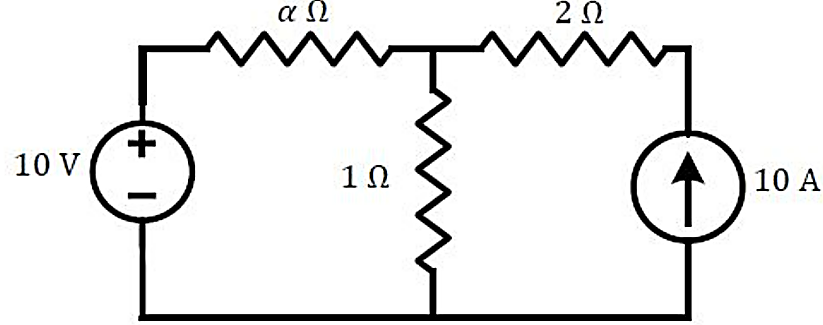
Sign in to UnlockAll the elements in the circuit are ideal. The power delivered by the source in watts is

0
50
100
dependent on the value of

Sign in to see the solution
Log in to view the explanation, track your attempts, and keep your progress.
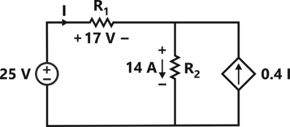
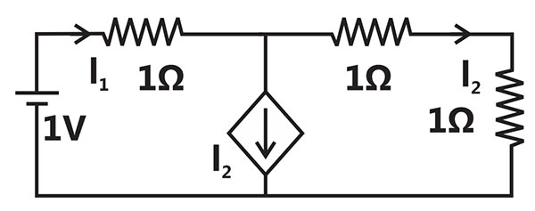
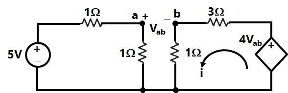
Sign in to UnlockFor the circuit shown in the figure, and . The voltage in Volts is __________ (Round off to 1 decimal place).


Sign in to see the solution
Log in to view the explanation, track your attempts, and keep your progress.
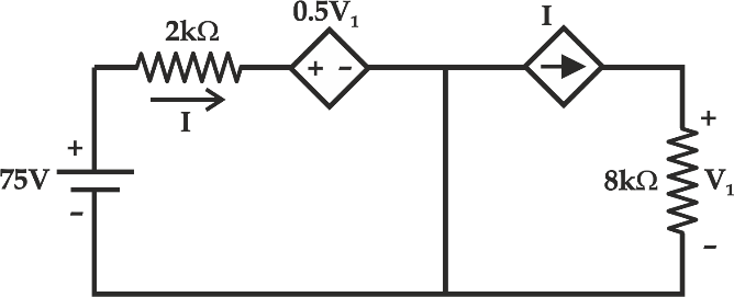
Sign in to UnlockIn the circuit shown below, the magnitude of voltage V1 in volts, across the 8 kΩ resistor is ________ . (round off to nearest integer)
Sign in to see the solution
Log in to view the explanation, track your attempts, and keep your progress.
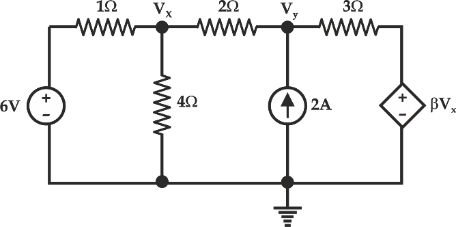
Sign in to UnlockIn the given circuit, for voltage Vy to be zero, value of β should be_________ (round off to 2 decimal places).
Sign in to see the solution
Log in to view the explanation, track your attempts, and keep your progress.
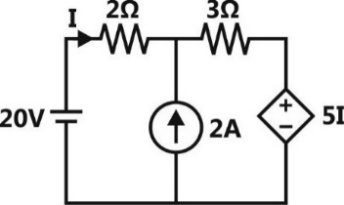
Sign in to UnlockThe current I flowing in the circuit shown below in amperes (round off to one decimal place) is ____________.
Sign in to see the solution
Log in to view the explanation, track your attempts, and keep your progress.
Sign in to UnlockThe current I flowing in the circuit shown below in amperes is ________.
Sign in to see the solution
Log in to view the explanation, track your attempts, and keep your progress.
Sign in to UnlockThe power supplied by the 25 V source in the figure shown below is ____________ W.
Sign in to see the solution
Log in to view the explanation, track your attempts, and keep your progress.
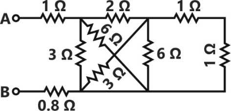
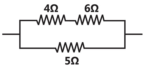
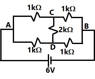
Sign in to UnlockThe equivalent resistance between the terminals A and B is __________ .

Sign in to see the solution
Log in to view the explanation, track your attempts, and keep your progress.
Sign in to UnlockIn the circuit shown below, the maximum power transferred to the resistor R is _____W.
Sign in to see the solution
Log in to view the explanation, track your attempts, and keep your progress.
Sign in to UnlockIn the circuit shown below, the value of capacitor C required for maximum power to be transferred to the load is
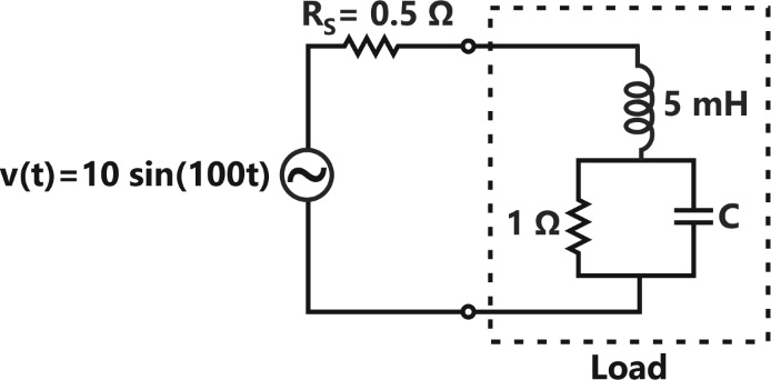
1 nF

1 mF
10 mF
Sign in to see the solution
Log in to view the explanation, track your attempts, and keep your progress.
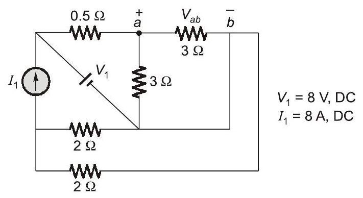
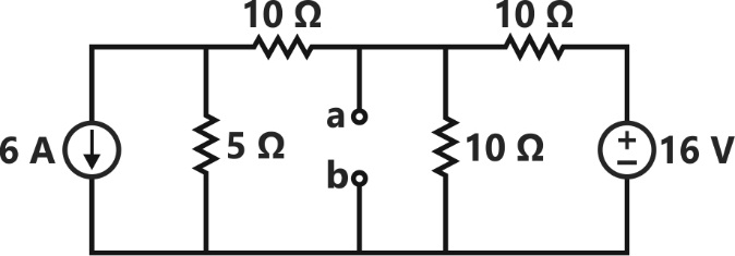
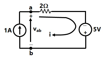
Sign in to UnlockFor the network given in figure below, the Thevenin’s voltage Vab is
Sign in to see the solution
Log in to view the explanation, track your attempts, and keep your progress.
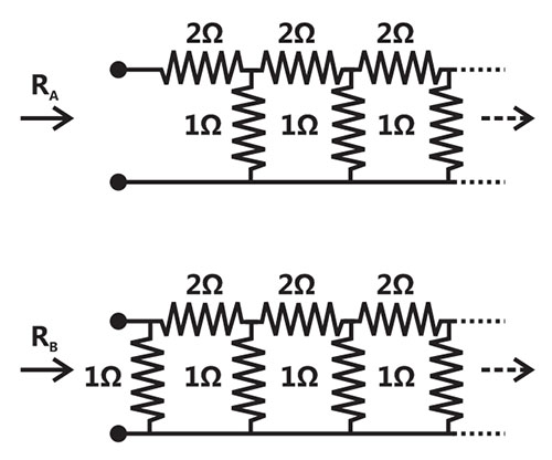
Sign in to Unlockand are the input resistances of circuits as shown below. The circuit extends infinitely in the direction shown. Which one of the following statements is TRUE?


Sign in to see the solution
Log in to view the explanation, track your attempts, and keep your progress.
Sign in to UnlockIn the portion of a circuit shown, if the heat generated in resistance is 10 calories per second, then heat generated by the resistance, in calories per second, is__________.


Sign in to see the solution
Log in to view the explanation, track your attempts, and keep your progress.
Sign in to UnlockIn the given circuit, the current supplied by the battery, in ampere, is______________
Sign in to see the solution
Log in to view the explanation, track your attempts, and keep your progress.
Sign in to UnlockIn the circuit shown below, the node voltage is ________________V.

Sign in to see the solution
Log in to view the explanation, track your attempts, and keep your progress.
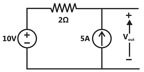
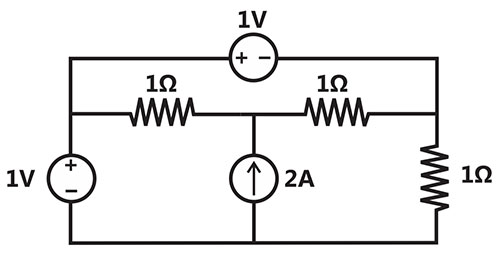
Sign in to UnlockIn the circuit shown below, the voltage and current sources are ideal. The voltage across the current source, in volts, is

Sign in to see the solution
Log in to view the explanation, track your attempts, and keep your progress.
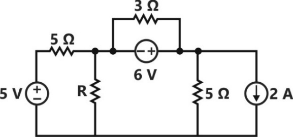
Sign in to UnlockThe voltages developed across the and resistors shown in the figure are 6V and 2V respectively, with the polarity as marked. What is the power (in Watt) delivered by the 5V voltage source?


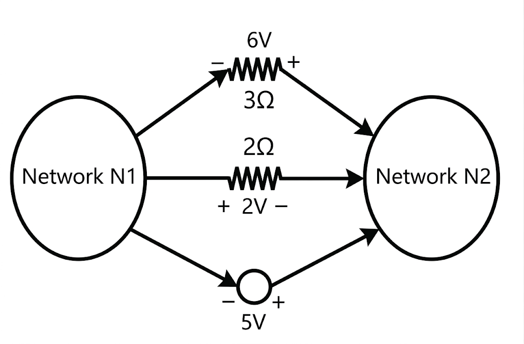
Sign in to see the solution
Log in to view the explanation, track your attempts, and keep your progress.
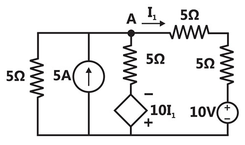
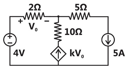
Sign in to UnlockIn the given circuit, the parameter k is positive, and the power dissipated in the 2 resistor is 12.5W. The value of k is ____________.

Sign in to see the solution
Log in to view the explanation, track your attempts, and keep your progress.
Sign in to UnlockThe three circuit elements shown in the figure are part of an electric circuit. The total power absorbed by the three circuit elements in watt is _______________.
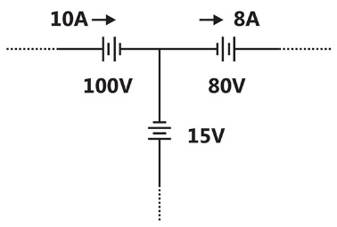
Sign in to see the solution
Log in to view the explanation, track your attempts, and keep your progress.
Sign in to UnlockAn incandescent lamp is marked 40W, 240V. If resistance at room temperature is and temperature coefficient of resistance is , then its ‘ON’ state filament temperature is is approximately______________.


Sign in to see the solution
Log in to view the explanation, track your attempts, and keep your progress.
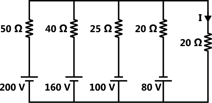
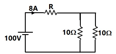
Sign in to UnlockIn the figure, the value of resistor R is (25 + I/2) ohms, where I is the current in amperes. The current I is ________________.
Sign in to see the solution
Log in to view the explanation, track your attempts, and keep your progress.
Sign in to UnlockThe power delivered by the current source, in the figure is_________.
Sign in to see the solution
Log in to view the explanation, track your attempts, and keep your progress.
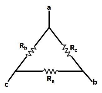
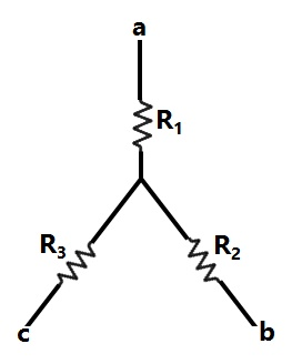
Sign in to UnlockConsider a delta connection of resistors and its equivalent star connection as shown below. If all elements of the delta connection are scaled by a factor k, k>0, the element of the corresponding star equivalent will be scaled by a factor of
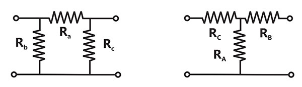

k
1/k

Sign in to see the solution
Log in to view the explanation, track your attempts, and keep your progress.
Sign in to UnlockIf , then is


Sign in to see the solution
Log in to view the explanation, track your attempts, and keep your progress.
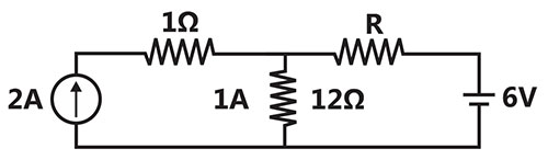
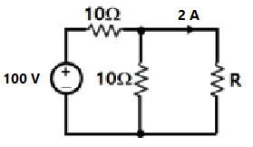
Sign in to UnlockIf the resistor draws a current of 1 A as shown in the figure, the value of resistance R is


Sign in to see the solution
Log in to view the explanation, track your attempts, and keep your progress.
Sign in to UnlockThe current through the 2kΩ resistance in the circuit shown is
Sign in to see the solution
Log in to view the explanation, track your attempts, and keep your progress.
Sign in to UnlockHow many 200W/220V incandescent lamps connected in series would consume the same total power as a single 100W/220V incandescent lamp?
Sign in to see the solution
Log in to view the explanation, track your attempts, and keep your progress.
Sign in to UnlockAssuming ideal elements in the circuit shown below, the voltage will be

Sign in to see the solution
Log in to view the explanation, track your attempts, and keep your progress.
Sign in to UnlockIn the circuit shown in the figure. The value of the current i will be given by
Sign in to see the solution
Log in to view the explanation, track your attempts, and keep your progress.
Sign in to UnlockThe current i(t) sketched in the figure flows through an initially uncharged 0.3nF capacitor.
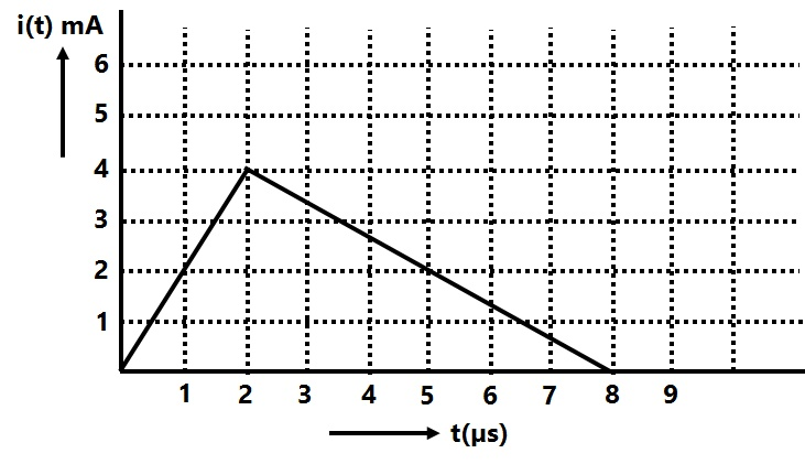
The charge stored in the capacitor at t = 5µs, will be
Sign in to see the solution
Log in to view the explanation, track your attempts, and keep your progress.
Sign in to UnlockThe current i(t) sketched in the figure flows through an initially uncharged 0.3nF capacitor.
The capacitor charged up to 5µs, as per the current profile given in the figure, is connected across an
inductor of 0.6mH. Then the value of voltage across the capacitor after 1µs will approximately be
Sign in to see the solution
Log in to view the explanation, track your attempts, and keep your progress.
Sign in to UnlockA 3 V dc supply with an internal resistance of 2Ω supplies a passive non-linear resistance characterized by the relation. The power dissipated in the non linear resistance is

Sign in to see the solution
Log in to view the explanation, track your attempts, and keep your progress.
Sign in to UnlockFigure the value of R is
Sign in to see the solution
Log in to view the explanation, track your attempts, and keep your progress.
Sign in to UnlockIn figure, the value of the source voltage is
Sign in to see the solution
Log in to view the explanation, track your attempts, and keep your progress.
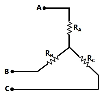
Sign in to UnlockIn figure, Ra, Rb and Rc are 20Ω, 10Ω and 10Ω respectively. The resistance R1, R2 and R3 in Ω of an equivalent star-connection are
Sign in to see the solution
Log in to view the explanation, track your attempts, and keep your progress.
Sign in to UnlockIn figure, the value of resistance R in Ω is
Sign in to see the solution
Log in to view the explanation, track your attempts, and keep your progress.
Sign in to UnlockFigure shows the waveform of the current passing through an inductor of resistance 1Ω and inductance 2 H. The energy absorbed by the inductor in the first four seconds is
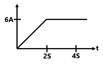
Sign in to see the solution
Log in to view the explanation, track your attempts, and keep your progress.
Sign in to UnlockIn Figure, the potential difference between points P and Q is
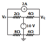
Sign in to see the solution
Log in to view the explanation, track your attempts, and keep your progress.
Sign in to UnlockIn Figure the value of R is
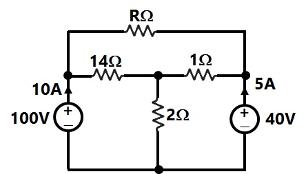
Sign in to see the solution
Log in to view the explanation, track your attempts, and keep your progress.
Sign in to UnlockIn the resistor network shown in Figure, all resistor values are 1Ω. A current of 1A passes from terminal a to terminal b, as shown in the figure. Calculate the voltage between terminals a and b. [Hint: You may exploit the symmetry of the circuit].
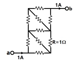
Sign in to see the solution
Log in to view the explanation, track your attempts, and keep your progress.
Sign in to UnlockTwo incandescent light bulbs of 40W and 60W rating are connected in series across the mains.
Then
Sign in to see the solution
Log in to view the explanation, track your attempts, and keep your progress.
Sign in to UnlockConsider the star network shown in Figure. The resistance between terminals A and B with C open is 6Ω, between terminals B and C with A open is 11Ω, and between terminals C and A with B open is 9Ω. Then


Sign in to see the solution
Log in to view the explanation, track your attempts, and keep your progress.
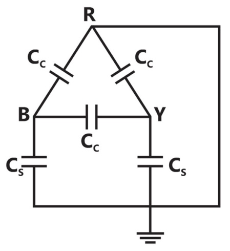
Sign in to UnlockFor the circuit shown in fig. the capacitance measured between terminals B and Y will be


Sign in to see the solution
Log in to view the explanation, track your attempts, and keep your progress.
Sign in to UnlockThe color code of a 1kΩ resistance is:
Sign in to see the solution
Log in to view the explanation, track your attempts, and keep your progress.
Sign in to UnlockWhen a resistor R is connected to a current source, it consumes a power of 18W. When the same R is connected to a voltage source having the same magnitude as the current source, the power absorbed by R is 4.5W. The magnitude of the current source and the value of R are
and


3A and

1A and 18Ω
6A and 0.5Ω
Sign in to see the solution
Log in to view the explanation, track your attempts, and keep your progress.
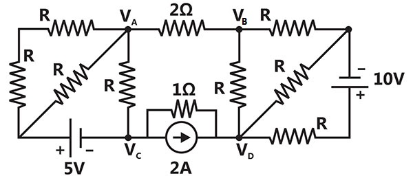
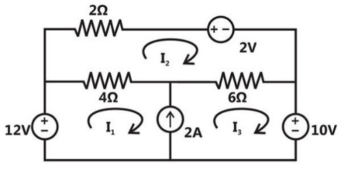
Sign in to UnlockSolve the circuit shown in figure using the mesh method of analysis and determine the mesh currents and . Evaluate the power developed in the 10V voltage source.


Sign in to see the solution
Log in to view the explanation, track your attempts, and keep your progress.
Sign in to UnlockAn ideal voltage source will charge an ideal capacity
Sign in to see the solution
Log in to view the explanation, track your attempts, and keep your progress.
Sign in to UnlockA practical current source is usually represented by
Sign in to see the solution
Log in to view the explanation, track your attempts, and keep your progress.
Sign in to UnlockEnergy stored in a capacitor over a cycle, when excited by an a.c. source is
Sign in to see the solution
Log in to view the explanation, track your attempts, and keep your progress.
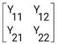
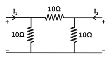
Sign in to UnlockFor the two port network shown in figure, the admittance matrix is . Then Find
\(Y_{11} + Y_{12} + Y_{22} + Y_{21} = ?\)
Sign in to see the solution
Log in to view the explanation, track your attempts, and keep your progress.
Sign in to UnlockA 10V battery with an internal resistance of 1Ω is connected across a nonlinear load whose V-I characteristic is given by . The current delivered by the battery is __________ A

Sign in to see the solution
Log in to view the explanation, track your attempts, and keep your progress.
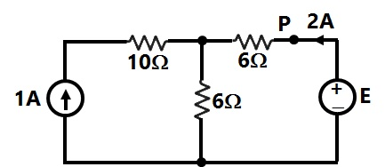
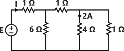
Sign in to UnlockThe values of E and I for the circuit shown in figure, are_________V and _________A. Then E+I= ?
Sign in to see the solution
Log in to view the explanation, track your attempts, and keep your progress.
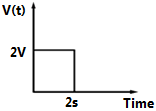
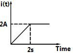
Sign in to UnlockThe voltage and current waveforms for an element are shown in figure. The circuit element is _________And its value is
Sign in to see the solution
Log in to view the explanation, track your attempts, and keep your progress.
Sign in to UnlockIn the circuit shown in figure X is an element which always absorbs power. During a particular operations, it sets up a current of 1 amp in the direction shown and absorbs a power . It is possible that X can absorb the same power for another current i, the value of this current is

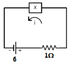


None of these
Sign in to see the solution
Log in to view the explanation, track your attempts, and keep your progress.
Sign in to UnlockAll the resistances in figure are each. The value of current ‘I’ is

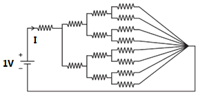


Sign in to see the solution
Log in to view the explanation, track your attempts, and keep your progress.
Sign in to Unlock