Digital Electronics
Boolean Algebra
Logic Gates
Questions mapped to Logic Gates under Boolean Algebra.
10
Total0
Attempted0
Correct0
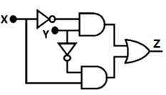
IncorrectIn the circuit shown below, X and Y are digital inputs, and Z is a digital output. The equivalent circuit is a
Sign in to see the solution
Log in to view the explanation, track your attempts, and keep your progress.
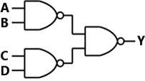
Sign in to UnlockIn the logic circuit shown in the figure. Y is given by




Sign in to see the solution
Log in to view the explanation, track your attempts, and keep your progress.
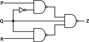
Sign in to UnlockFor a 3-input logic circuit shown below, the output Z can be expressed as




Sign in to see the solution
Log in to view the explanation, track your attempts, and keep your progress.
Sign in to UnlockA bulb in a staircase has two switches, one switch being at the ground floor and the other one at the first floor. The bulb can be turned ON and also can be turned OFF by any one of the switches irrespective of the state of the other switch. The logic of switching of the bulb resembles
Sign in to see the solution
Log in to view the explanation, track your attempts, and keep your progress.
Sign in to UnlockThe output Y of the logic circuit given below is

1
0
X

Sign in to see the solution
Log in to view the explanation, track your attempts, and keep your progress.
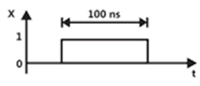
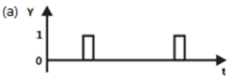
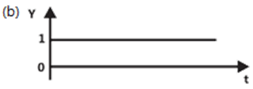
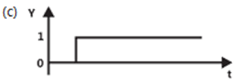
Sign in to UnlockThe TTL circuit shown in the figure is fed with the waveform X (also shown). All gates have equal propagation delay of 10ns. The output Y of the circuit is


Sign in to see the solution
Log in to view the explanation, track your attempts, and keep your progress.
Sign in to UnlockThe complete set of only those Logic Gates designated as Universal Gates is
Sign in to see the solution
Log in to view the explanation, track your attempts, and keep your progress.
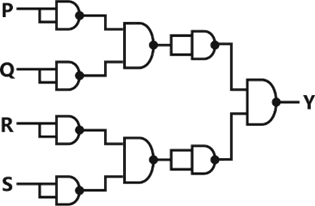
Sign in to UnlockFor the circuit shown in figure, the Boolean expression for the output Y in terms of inputs P, Q, R and S is




Sign in to see the solution
Log in to view the explanation, track your attempts, and keep your progress.
Sign in to UnlockThe output of a logic gate is “1” when all its inputs are at logic “0”. The gate is either.
Sign in to see the solution
Log in to view the explanation, track your attempts, and keep your progress.
Sign in to UnlockThe Boolean expression for the output of the logic circuit shown in figure is





Sign in to see the solution
Log in to view the explanation, track your attempts, and keep your progress.
Sign in to Unlock