Power Electronics
Chopper
Boost Converter
Questions mapped to Boost Converter under Chopper.
8
Total0
Attempted0
Correct0
IncorrectConsider the boost converter circuit shown. Assume that the semiconductor devices are ideal. In steady state, the inductor current rises linearly from 0 A to 6 A in the first and then falls linearly from 6 A to 0 A in the next of every switching cycle as shown. The load resistance is and the capacitance is .


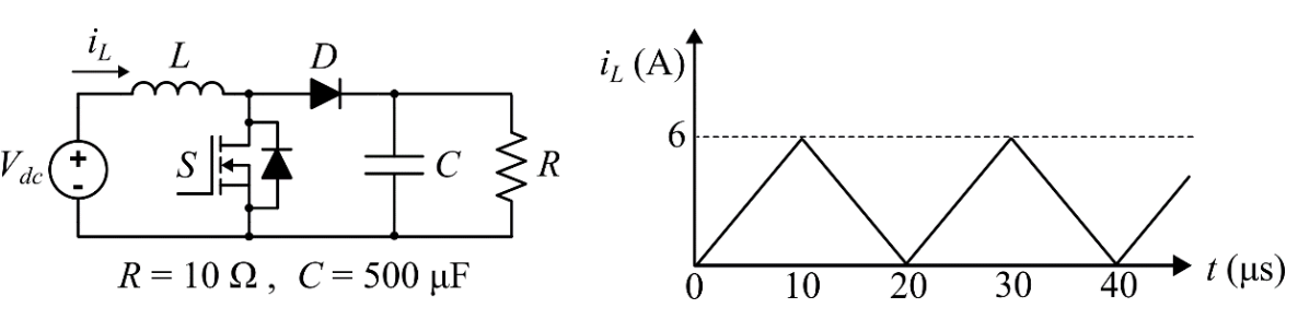
Neglect the ripple in the output voltage. What is the input voltage ?

Sign in to see the solution
Log in to view the explanation, track your attempts, and keep your progress.
Sign in to UnlockConsider the boost converter shown. Switch Q is operating at 25 kHz with a duty cycle of 0.6. Assume the diode and switch to be ideal. Under steady-state condition, the average resistance as seen by the source is _______Ω. (Round off to 2 decimal places.)


Sign in to see the solution
Log in to view the explanation, track your attempts, and keep your progress.
Sign in to UnlockIn a DC-DC boost converter, the duty ratio is controlled to regulate the output voltage at 48 V. The input DC voltage is 24 V. The output power is 120 W. The switching frequency is 50 kHz. Assume ideal components and a very larger output filter capacitor. The converter operates at the boundary between continuous and discontinuous conduction modes. The value of the boost inductor (in ) is __________.

Sign in to see the solution
Log in to view the explanation, track your attempts, and keep your progress.
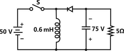
Sign in to UnlockIn the circuit shown all elements are ideal and the switch S is operated at 10kHz and 60% duty ratio. The capacitor is large enough so that the ripple across it is negligible and at steady state acquires a voltage as shown. The peak current in amperes drawn from the 50 V DC source is ___________. (Give the answer up to one decimal place).
Sign in to see the solution
Log in to view the explanation, track your attempts, and keep your progress.
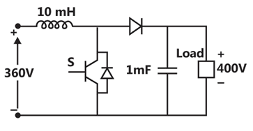
Sign in to UnlockA DC-DC boost converter, as shown in the figure below, is used to boost 360V to 400V, at a power of a 4kW. All devices are ideal, considering continuous inductor current, the rms current in the solid state switch (S), in ampere, is_______________.
Sign in to see the solution
Log in to view the explanation, track your attempts, and keep your progress.
Sign in to UnlockA step-up chopper is used to feed a load at 400V dc from a 250V dc source. The inductor current is continuous. If the ‘off’ time of the switch is , the switching frequency of the chopper in kHz is____.

Sign in to see the solution
Log in to view the explanation, track your attempts, and keep your progress.
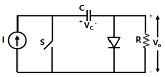
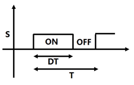
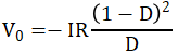
Sign in to UnlockIn the circuit shown in Figure, the source I is a dc current source. The switch S is operated with a time period T and a duty ratio D. You may assume that the capacitance C has a finite value which is large enough so that the voltage. has negligible ripple. Calculate the following under steady state conditions, in terms of D, I and R.

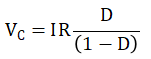
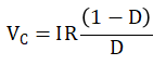
(a) The voltage, with the polarity shown in Figure.
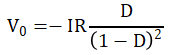
(b) The average output voltage, with the polarity shown.

Sign in to see the solution
Log in to view the explanation, track your attempts, and keep your progress.
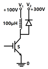
Sign in to UnlockThe semiconductor switch S in the circuit of Figure is operated at a frequency of 20 kHz and a duty ratio D=0.5. The circuit operates in the steady state. Calculate the power transferred from the dc voltage source to the dc voltage source.


Sign in to see the solution
Log in to view the explanation, track your attempts, and keep your progress.
Sign in to Unlock