Power Electronics
Chopper
Buck Boost Converter
Questions mapped to Buck Boost Converter under Chopper.
9
Total0
Attempted0
Correct0
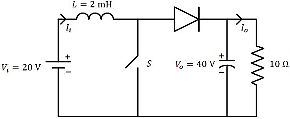
IncorrectIn the DC-DC converter shown in the figure, the current through the inductor is continuous. The switching frequency is 500 Hz. The voltage across the load is assumed to be constant and ripple free. The peak inductor current in amperes is ________(rounded off to the nearest integer).

Sign in to see the solution
Log in to view the explanation, track your attempts, and keep your progress.
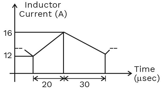
Sign in to UnlockThe steady state current flowing through the inductor of a DC-DC buck boost converter is given in the figure below. If the peak-to-peak ripple in the output voltage of the converter is 1 V, then the value of the output capacitor, in µF, is _______________. (round off to nearest integer)
Sign in to see the solution
Log in to view the explanation, track your attempts, and keep your progress.
Sign in to UnlockConsider the buck-boost converter shown. Switch Q is operating at 25 kHz and 0.75 duty-cycle. Assume diode and switch to be ideal. Under steady-state condition, the average current flowing through the inductor is _______A.

Sign in to see the solution
Log in to view the explanation, track your attempts, and keep your progress.
Sign in to UnlockA DC to dc converter shown in the figure is charging a battery bank, B2 whose voltage is constant at 150V. B1 is another battery bank whose voltage is constant at 50V. The value of the inductor, L is 5mH and the ideal switch, S is operated with a switching frequency of 5 kHz with a duty ratio of 0.4. Once the circuit has attained steady state and assuming the diode D to be ideal, the power transferred from B1 to B2 (in Watt) is _____ (up to 2 decimal places).

Sign in to see the solution
Log in to view the explanation, track your attempts, and keep your progress.
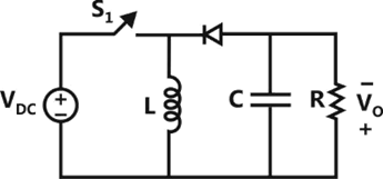
Sign in to UnlockThe input voltage of the buck-boost converter shown below varies from 32 V to 72 V. Assume that all components are ideal, inductor current is continuous, and output voltage is ripple free. The range of duty ratio D of the converter for which the magnitude of the steady-state output voltage remains constant at 48 V is





Sign in to see the solution
Log in to view the explanation, track your attempts, and keep your progress.
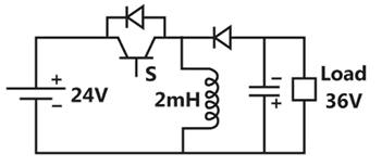
Sign in to UnlockA buck-boost DC-DC converter, shown in the figure below, is used to convert 24V battery voltage to 36 V DC voltage to feed a load of 72W. It is operated at 20kHz with an inductor of 2mH and output capacitor 1000μF. All devices are considered to be ideal. The peak voltage across the solid-state switch (S), in volt, is____________.
Sign in to see the solution
Log in to view the explanation, track your attempts, and keep your progress.
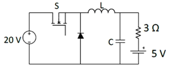
Sign in to UnlockIn the following chopper, the duty ratio of switch S is 0.4. If the inductor and capacitor are sufficiently large to ensure continuous inductor current and ripple free capacitor voltage, the charging current (in Ampere) of the 5 V battery, under steady-state, is _____________.
Sign in to see the solution
Log in to view the explanation, track your attempts, and keep your progress.
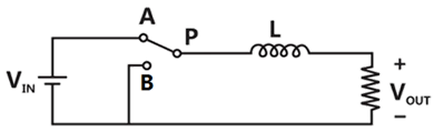
Sign in to UnlockThe power electronic converter shown in the figure has a single-pole double-throw switch. The pole P of the switch is connected alternately to throws A and B. The converter shown in figure is
Sign in to see the solution
Log in to view the explanation, track your attempts, and keep your progress.
Sign in to UnlockIn the circuit shown in the figure, the switch is operated at a duty cycle of 0.5. A large capacitor is connected across the load. The inductor current is assumed to be continuous. The average voltage across the load and the average current through the diode will respectively be

Sign in to see the solution
Log in to view the explanation, track your attempts, and keep your progress.
Sign in to Unlock