Power Electronics
Chopper
Thyristor Commutation Techniques
Questions mapped to Thyristor Commutation Techniques under Chopper.
9
Total0
Attempted0
Correct0
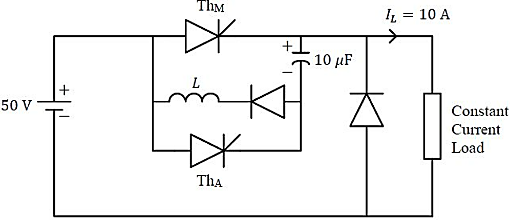
IncorrectA forced commutated thyristorized step-down chopper is shown in the figure. Neglect the ON-state drop across the power devices. Assume that the capacitor is initially charged to 50 V with the polarity shown in the figure. The load current can be assumed to be constant at 10 A. Initially, is and is OFF. The turn-off time available to in microseconds, when is triggered, is _______ (rounded off to the nearest integer).




Sign in to see the solution
Log in to view the explanation, track your attempts, and keep your progress.
Sign in to UnlockA voltage commutated chopper circuit, operated at 500Hz, is shown below
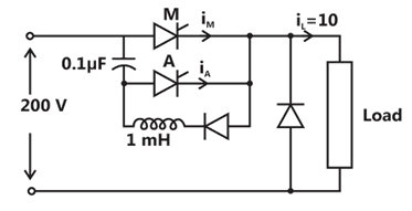
If the maximum value of load current is 10A, then the maximum current through the main (M) and auxiliary (A) thyristor will be




Sign in to see the solution
Log in to view the explanation, track your attempts, and keep your progress.
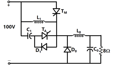
Sign in to UnlockIn the chopper circuit shown, the main thyristor is operated at a duty ratio of 0.8 which is much larger the commutation interval. If the maximum allowable reapplied dv/dt on is , what should be the theoretical minimum value of ? Assume current ripple through to be negligible.





Sign in to see the solution
Log in to view the explanation, track your attempts, and keep your progress.
Sign in to UnlockA voltage commutated chopper operating at 1 kHz is used to control the speed of dc motor as shown in figure. The load current is assumed to be constant at 10 A.
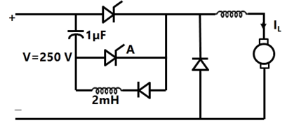
The minimum time in µsec for which the SCR M should be ON is
Sign in to see the solution
Log in to view the explanation, track your attempts, and keep your progress.
Sign in to UnlockA voltage commutated chopper operating at 1 kHz is used to control the speed of dc motor as shown in figure. The load current is assumed to be constant at 10 A.
The average output voltage of the chopper will be
Sign in to see the solution
Log in to view the explanation, track your attempts, and keep your progress.
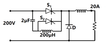
Sign in to UnlockFigure shows a chopper. The device S1 is the main switching device. S2 is the auxiliary commutation device. S1 is rated for 400V, 60A. S2 is rated for 400V, 30 A. the load current is 20 A. The main device operates with a duty ratio of 0.5. The peak current through S1 is
Sign in to see the solution
Log in to view the explanation, track your attempts, and keep your progress.
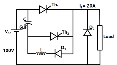
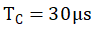
Sign in to UnlockA voltage commutated thyristor chopper circuit is shown in figure. The chopper is operated at 500 Hz with 50% duty ratio. The load takes a constant current of 20A.
(a) Evaluate the circuit turn off time for the main thyristor .

(b) Calculate the value of inductor L, if the peak current through the main thyristor is limited to 180% of the load current.
(c) Calculate the maximum instantaneous output voltage of the chopper.
L=0.234mH
Maximum instantaneous voltage = 200V
Maximum instantaneous voltage = 400V
Sign in to see the solution
Log in to view the explanation, track your attempts, and keep your progress.
Sign in to UnlockIn a thyristor dc chopper, which type of commutation results in best performance?
Sign in to see the solution
Log in to view the explanation, track your attempts, and keep your progress.
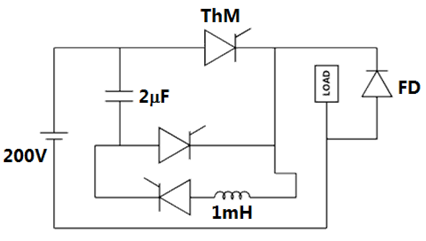
Sign in to UnlockConsider the chopper circuit of figure. The chopper operates at 400Hz and 50% duty cycle. The load current remains almost ripple free at 10A. Assuming the input voltage to be 200V and the devices to be ideal, the turn-off time available to the thyristor ThM is ____ μs.
Sign in to see the solution
Log in to view the explanation, track your attempts, and keep your progress.
Sign in to Unlock