Analog Electronics
Diode and Its Applications
Wave Shaping Circuits
Questions mapped to Wave Shaping Circuits under Diode and Its Applications.
6
Total0
Attempted0
Correct0
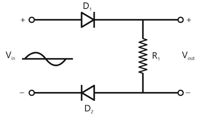
IncorrectFor the circuit shown below with ideal diodes the output will be




Sign in to see the solution
Log in to view the explanation, track your attempts, and keep your progress.
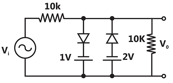
Sign in to UnlockAssuming the diodes to be ideal in the figure, for the output to be clipped, the input voltage must be outside the range

Sign in to see the solution
Log in to view the explanation, track your attempts, and keep your progress.
Sign in to UnlockA clipper circuit shown below
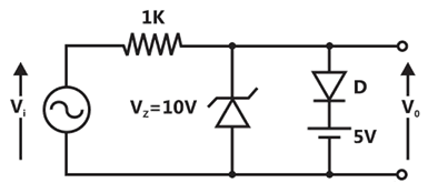
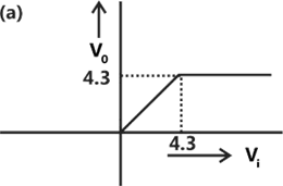
Assuming forward voltage drops of the diodes to be 0.7V, the input-output transfer characteristics of the circuit is
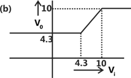
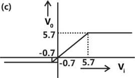
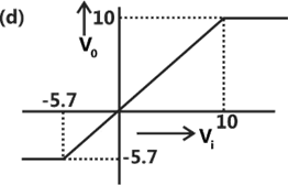
Sign in to see the solution
Log in to view the explanation, track your attempts, and keep your progress.
Sign in to UnlockAssuming the diodes and of the circuit shown in figure to be ideal ones, the transfer characteristics of the circuit will be


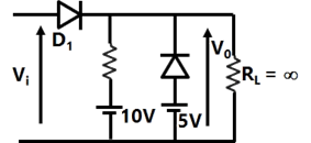
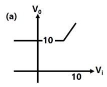
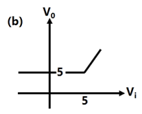
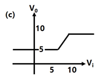
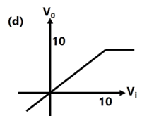
Sign in to see the solution
Log in to view the explanation, track your attempts, and keep your progress.
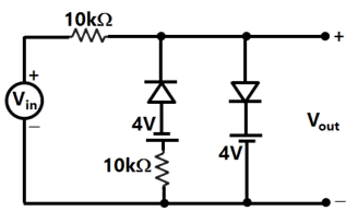
Sign in to UnlockA voltage signal 10 sinωt is applied to the circuit with ideal diodes, as shown in Figure. The maximum and minimum values of the output waveform of the circuit are respectively 10kΩ

Sign in to see the solution
Log in to view the explanation, track your attempts, and keep your progress.
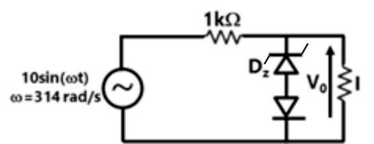
Sign in to UnlockThe cut-in voltage of both Zener diode and diode D shown in Figure is 0.7 V, while break down voltage of is 3.3 V and reverse breakdown voltage of D is 5V. The other parameters can be assumed to be the same as those of an ideal diode. The values of the peak output voltage are ........ ( Load Resistance = 1k Ohm )


Sign in to see the solution
Log in to view the explanation, track your attempts, and keep your progress.
Sign in to Unlock