Power Systems
Fault Analysis
Sequence Network
Questions mapped to Sequence Network under Fault Analysis.
9
Total0
Attempted0
Correct0
IncorrectThe two-bus power system shown in figure (i) has one alternator supplying a synchronous motor load through a - transformer. The positive, negative and zero-sequence diagrams of the system are shown in figures (ii), (iii) and (iv), respectively. All reactances in the sequence diagrams are in p.u. For a bolted line-to-line fault (fault impedance = zero) between phases ' ' and ' ' at bus 1 , neglecting all pre-fault currents, the magnitude of the fault current (from phase ' ' to ' ') in p.u. is _______ (Round off to 2 decimal places).




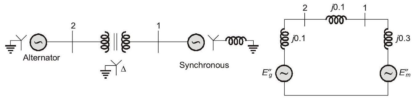
Fig. (i) : Single-line diagram of the power system
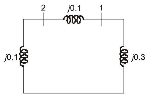
Fig. (iii) : Negative-sequence network Fig. (ii) : Positive-sequence network
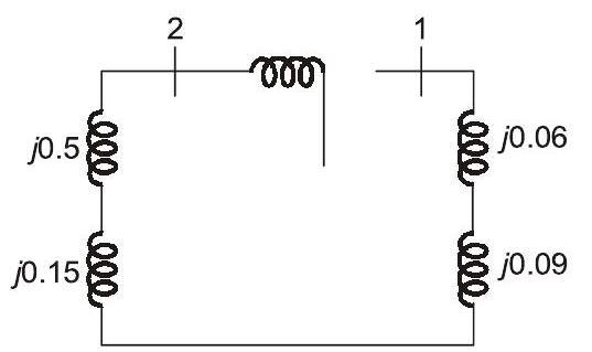
Fig. (iv) : Zero-sequence network
Sign in to see the solution
Log in to view the explanation, track your attempts, and keep your progress.
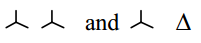
Sign in to UnlockA 2 – bus system and corresponding zero sequence network are shown in the figure.

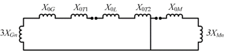
The two transformers and are connected as,





Sign in to see the solution
Log in to view the explanation, track your attempts, and keep your progress.
Sign in to UnlockFor a fully transposed transmission line
Sign in to see the solution
Log in to view the explanation, track your attempts, and keep your progress.
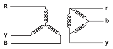
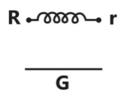
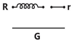
Sign in to UnlockThe zero-sequence circuit of the three phase transformers shown in the figure is
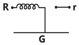
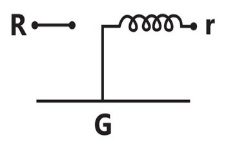
Sign in to see the solution
Log in to view the explanation, track your attempts, and keep your progress.
Sign in to UnlockA 3-phase transmission line is shown in the figure:
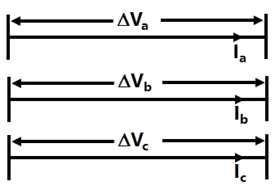
Voltage drop across the transmission line is given by the following equation:

Shunt capacitance of the line can be neglected. If the line has positive sequence impedance of 15Ω and zero sequence impedance of 48Ω, then the values of , and will be






Sign in to see the solution
Log in to view the explanation, track your attempts, and keep your progress.
Sign in to UnlockThe parameters of a transposed overhead transmission line are given as:
Self reactance / km and Mutual reactance


The positive sequence reactance and zero sequence reactance, respectively, in Ω/km are


Sign in to see the solution
Log in to view the explanation, track your attempts, and keep your progress.
Sign in to UnlockA generator is connected to a transformer which feeds another transformer through a short feeder (see Figure). The zero sequence impedance values are expressed in pu on a common base and are indicated in Figure. The Thevenin’s equivalent zero sequence impedance at point B is
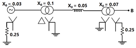
Sign in to see the solution
Log in to view the explanation, track your attempts, and keep your progress.
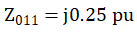
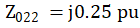
Sign in to UnlockTwo transposed 3 phase lines run parallel to each other, the equation describing the voltage drop in both lines is given below.

Compute the self and mutual zero sequence impedances of this system i.e. compute in the following equations



Where are the zero sequence voltage drops and currents for the two lines respectively



Sign in to see the solution
Log in to view the explanation, track your attempts, and keep your progress.
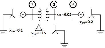
Sign in to UnlockFor the network shown in fig, the zero sequence reactance’s in p.u. are indicated. The zero sequence driving point reactance of the node 3 is:
Sign in to see the solution
Log in to view the explanation, track your attempts, and keep your progress.
Sign in to Unlock