Control Systems
Frequency Domain Analysis
Frequency Response
Questions mapped to Frequency Response under Frequency Domain Analysis.
16
Total0
Attempted0
Correct0
IncorrectThe transfer function of a real system, H(s), is given as:
where A, B, C and D are positive constants. This system cannot operate as

Sign in to see the solution
Log in to view the explanation, track your attempts, and keep your progress.
Sign in to UnlockAn LTI system is shown in the figure where G(s) . The steady state output of the system, to the input r(t), is given as The values of a and b will be



Sign in to see the solution
Log in to view the explanation, track your attempts, and keep your progress.
Sign in to UnlockA signal generator having a source resistance of . is set to generate a 1 kHz sinewave. Open circuit terminal voltage is 10 V peak-to-peak. Connecting a capacitor across the terminals reduces the voltage to 8 V peak-to-peak. The value of this capacitor is ________ . (Round off to 2 decimal places.)


Sign in to see the solution
Log in to view the explanation, track your attempts, and keep your progress.
Sign in to UnlockA stable real linear time-invariant system with single pole at p, has a transfer function with a dc gain of 5. The smallest positive frequency, in rad/s, at unity gain is closest to:

Sign in to see the solution
Log in to view the explanation, track your attempts, and keep your progress.
Sign in to UnlockThe transfer function of a system is given by, . Let the output of the system be for the input, . Then the minimum and maximum values of (in radians) are respectively








Sign in to see the solution
Log in to view the explanation, track your attempts, and keep your progress.
Sign in to UnlockThe transfer function of a system is . The steady state output y(t) is A for the input . The value of A and , respectively are








Sign in to see the solution
Log in to view the explanation, track your attempts, and keep your progress.
Sign in to UnlockThe phase cross-over frequency of the transfer function in rad/s is



3

Sign in to see the solution
Log in to view the explanation, track your attempts, and keep your progress.
Sign in to UnlockConsider a linear time-invariant system with transfer function

If the input is cos(t) and the steady output is , then the value of A is___________.

Sign in to see the solution
Log in to view the explanation, track your attempts, and keep your progress.
Sign in to UnlockThe transfer function of a second order real system with a perfectly flat magnitude response of unity has a pole at
(2 – j3). List all the poles and zeroes.
Sign in to see the solution
Log in to view the explanation, track your attempts, and keep your progress.
Sign in to UnlockA system with transfer function
is excited by . The steady state output of the system is zero at






Sign in to see the solution
Log in to view the explanation, track your attempts, and keep your progress.
Sign in to UnlockA system with zero initial conditions has the closed loop transfer function. The system output is zero at the frequency

Sign in to see the solution
Log in to view the explanation, track your attempts, and keep your progress.
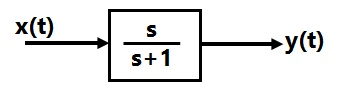
Sign in to UnlockIn the system shown in figure, the input x(t)=sin t. In the steady-state, the response y(t) will be




Sign in to see the solution
Log in to view the explanation, track your attempts, and keep your progress.
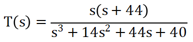
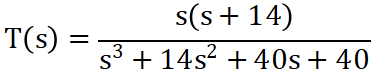
Sign in to UnlockDetermine the transfer function of the system having the following state variable representation:




Sign in to see the solution
Log in to view the explanation, track your attempts, and keep your progress.
Sign in to UnlockThe closed-loop transfer function of a control system is given by . For the input , the steady state value of c(t) is equal to



1


Sign in to see the solution
Log in to view the explanation, track your attempts, and keep your progress.
Sign in to UnlockThe block diagram of the control system is given in the figure.
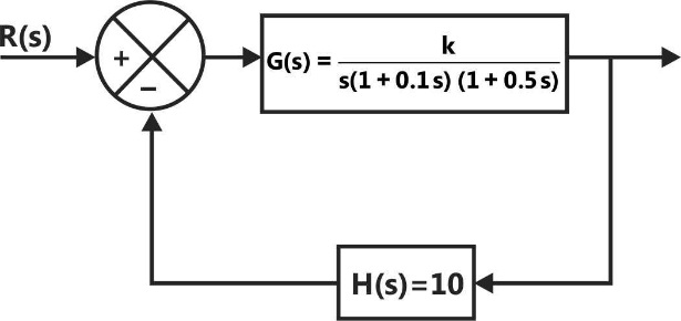
Nyquist locus

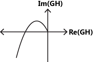
Phase cross-over frequency = 4.472 rad/sec
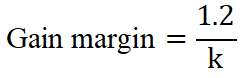
For K=1.2, phase margin = 0
Sign in to see the solution
Log in to view the explanation, track your attempts, and keep your progress.
Sign in to UnlockAn underdamped second-order system having a transfer function of the form has a frequency response plot shown in the figure. Then the system gain K is _______________ and the damping factor is approximately ___________________.

System gain K = 2
Damping factor

System gain K = 1
Damping factor

Sign in to see the solution
Log in to view the explanation, track your attempts, and keep your progress.
Sign in to Unlock