Power Electronics
Inverter
Single Phase Inverter
Questions mapped to Single Phase Inverter under Inverter.
20
Total0
Attempted0
Correct0
IncorrectConsider the single-phase voltage source inverter circuit feeding an inductive load . Assume that the power MOSFET switches are ideal. and are switched on during the first \(\scriptstyle 10\mu S\), and and are switched on during the next \(\scriptstyle 10\mu S\) in a switching cycle. The switches in the same leg are thus switched in a complementary fashion. Neglect the dead time. The waveform of the inductor current ( ) in the steady state is triangular with a peak value of 5 A as shown.






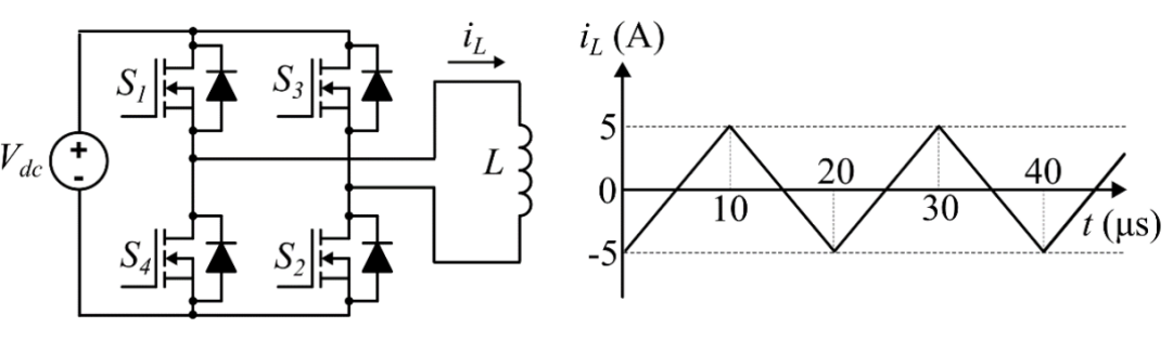
The rms value of the current through the switch is:
Sign in to see the solution
Log in to view the explanation, track your attempts, and keep your progress.
Sign in to UnlockA single-phase full bridge voltage source inverter (VSI) feeds a purely inductive load. The inverter output voltage is a square wave in conduction mode. The fundamental frequency of the output voltage is 50 Hz. If the DC input voltage of the inverter is 100 V and the value of the load inductance is 20mH, the peak-to peak load current in amperes is ________ (rounded off to the nearest integer).

Sign in to see the solution
Log in to view the explanation, track your attempts, and keep your progress.
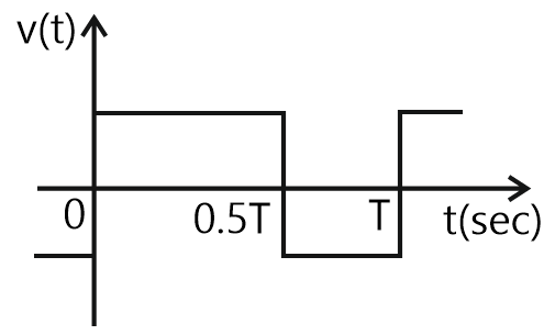
Sign in to UnlockConsider an ideal full-bridge single-phase DC-AC inverter with a DC bus voltage magnitude of 1000 V. The inverter output voltage 𝑣(𝑡) shown below, is obtained when diagonal switches of the inverter are switched with 50% duty cycle. The inverter feeds a load with a sinusoidal current given by, , where . The active power, in watts, delivered to the load is _________. (round off to nearest integer)


Sign in to see the solution
Log in to view the explanation, track your attempts, and keep your progress.
Sign in to UnlockA single-phase full-bridge inverter fed by a 325 V DC produces a symmetric quasi-square waveform across ‘ab’ as shown. To achieve a modulation index of 0.8, the angle 0 expressed in degrees should be ________. (Round off to 2 decimal places.)
(Modulation index is defined as the ratio of the peak of the fundamental component of to the applied DC value.)


Sign in to see the solution
Log in to view the explanation, track your attempts, and keep your progress.
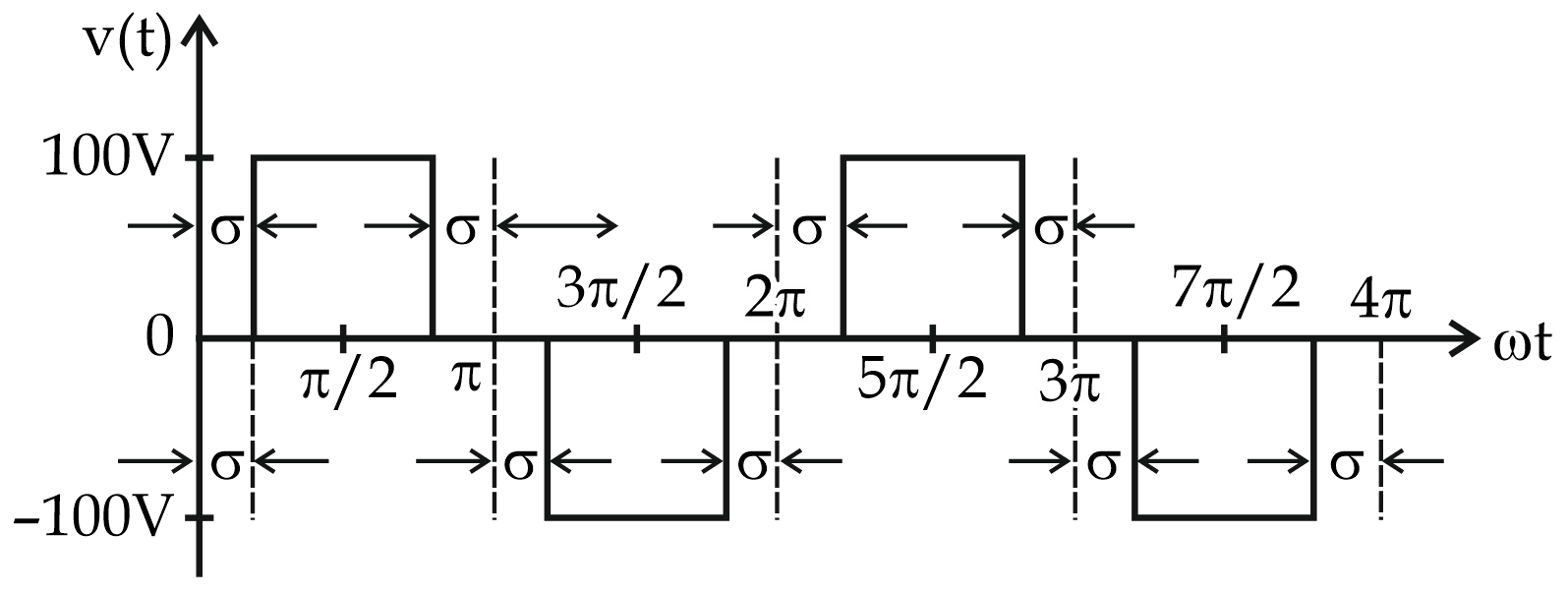
Sign in to UnlockA single-phase inverter is fed from a 100 V dc source and is controlled using a quasi-square wave modulation scheme to produce an output waveform, v(t) as shown. The angle σ is adjusted to entirely eliminate the harmonic component from the output voltage. Under this condition for v(t), the magnitude of the harmonic component as a percentage of the magnitude of the fundamental component is _________. (rounded off to 2 decimal places).


Sign in to see the solution
Log in to view the explanation, track your attempts, and keep your progress.
Sign in to UnlockThe output voltage of a single-phase full bridge voltage source inverter is controlled by unipolar PWM with one pulse per half cycle. For the fundamental rms component of output voltage to be 75% of DC voltage, the required pulse width in degrees (round off up to one decimal place) is _____________.
Sign in to see the solution
Log in to view the explanation, track your attempts, and keep your progress.
Sign in to UnlockIn the converter circuit shown below, the switches are controlled such that the load voltage is a 400 Hz square wave.

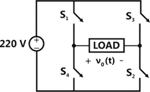
The RMS value of the fundamental component of in volts is ______________.
Sign in to see the solution
Log in to view the explanation, track your attempts, and keep your progress.
Sign in to UnlockThe figure below shows a half-bridge voltage source inverter supplying an RL-load with and . The desired fundamental frequency of the load voltage is 50 Hz. The switch control signals of the converter are generated using sinusoidal pulse width modulation with modulation index, . At 50 Hz, the RL-load draws an active power of 1.44 kW. The value of DC source voltage in volts is




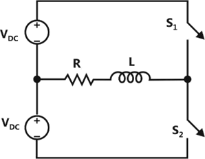

500


Sign in to see the solution
Log in to view the explanation, track your attempts, and keep your progress.
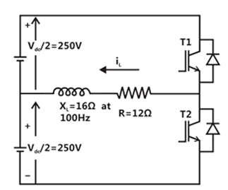
Sign in to UnlockThe switches T1 and T2 in figure
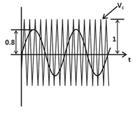
(a) are switched in a complementary fashion with sinusoidal pulse width modulation technique. The modulating voltage and the triangular carrier voltage are as shown in figure


(b). The carrier frequency is 5kHz. The peak value of the 100Hz component of the load current , in ampere, is _______________.

Sign in to see the solution
Log in to view the explanation, track your attempts, and keep your progress.
Sign in to UnlockA single-phase full-bridge voltage source inverter (VSI) is fed from a 300V battery, A pulse of duration is used to trigger the appropriate devices in each half-cycle. The rms value of the fundamental component of the output voltage, in volts, is

Sign in to see the solution
Log in to view the explanation, track your attempts, and keep your progress.
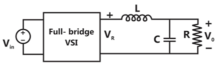
Sign in to UnlockThe single-phase full-bridge voltage inverter (VSI), shown in figure, has an output frequency of 50 Hz. It uses unipolar pulse width modulation with switching frequency of 50 kHz and modulation index of 0.7. For , L = 9.55 mH, C = 63.66 , R = 5Ω, the amplitude of the fundamental component in the output voltage (in Volt) under steady-state is __________________.



Sign in to see the solution
Log in to view the explanation, track your attempts, and keep your progress.
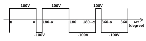
Sign in to UnlockThe figure shows one period of the output voltage of an inverter. should be chosen such that . If rms value of the fundamental component is 50V, then in degree is ____________


Sign in to see the solution
Log in to view the explanation, track your attempts, and keep your progress.
Sign in to UnlockA single-phase voltage source inverter shown in figure feeding power to a load. The triggering pulses of the devices are also shown in the figure.
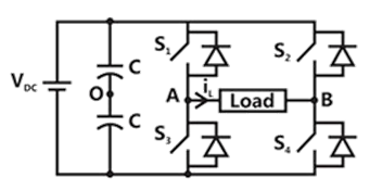
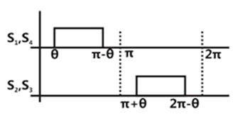
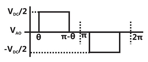
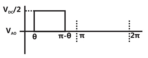
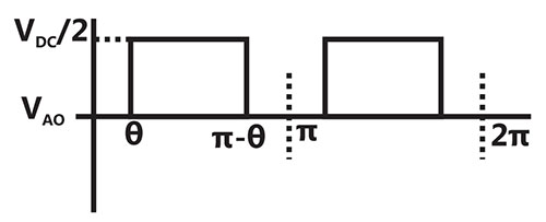
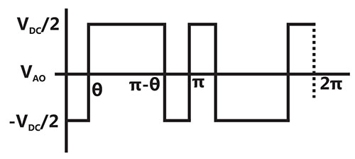
If the load current is sinusoidal and is zero at the node voltage has the waveform


Sign in to see the solution
Log in to view the explanation, track your attempts, and keep your progress.
Sign in to UnlockThe Voltage Source Inverter (VSI) shown in the figure below is switched to provide a 50 Hz, square-wave ac output voltage (V₀) across an R-L load. Reference polarity of V₀ and reference direction of the output current i₀ are indicated in the figure. It is given that R=3Ω, L=9.55mH.
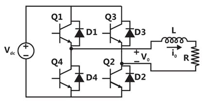
In the interval when V₀<0 and i₀>0 the pair of devices which conducts the load current is
Sign in to see the solution
Log in to view the explanation, track your attempts, and keep your progress.
Sign in to UnlockThe Voltage Source Inverter (VSI) shown in the figure below is switched to provide a 50 Hz, square-wave ac output voltage (V₀) across an R-L load. Reference polarity of V₀ and reference direction of the output current i₀ are indicated in the figure. It is given that R=3Ω, L=9.55mH.
Appropriate transition i.e., Zero Voltage Switching (ZVS) /Zero Current Switching (ZCS) of the IGBTs during turn-on/turn-off is
Sign in to see the solution
Log in to view the explanation, track your attempts, and keep your progress.
Sign in to UnlockA single phase voltage source inverter is feeding a purely inductive load as shown in the figure.

The inverter is operated at 50Hz in 180° square wave mode. Assume that the load current does not have any dc component. The peak value of the inductor current will be

Sign in to see the solution
Log in to view the explanation, track your attempts, and keep your progress.
Sign in to Unlock"Six MOSFETs connected in a bridge configuration (having no other power device) MUST be operated as a Voltage Source Inverter (VSI)'". This statement is
Sign in to see the solution
Log in to view the explanation, track your attempts, and keep your progress.
Sign in to UnlockA single-phase voltage source inverter is controlled in a single pulse-width modulated mode with a pulse width of 150° in each half cycle. Total harmonic distortion is defined as , where is the RMS value of the fundamental component of the output voltage. The THD of output AC voltage waveform is


Sign in to see the solution
Log in to view the explanation, track your attempts, and keep your progress.
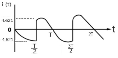
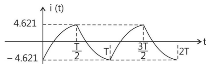
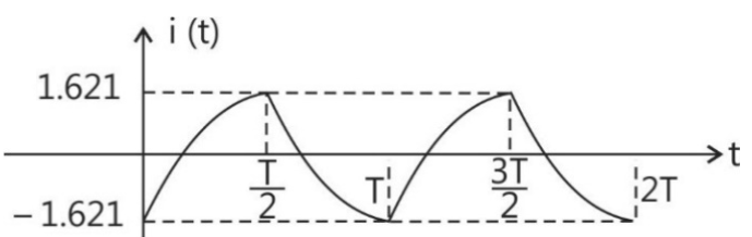
Sign in to UnlockA single-phase bridge inverter is fed from a 200V d.c. supply and is operated at 50Hz. It is connected to a load having a resistance of 20 ohms and an inductance of 0.2H. Draw the load current waveform in the steady indicating the peak values.
None
Sign in to see the solution
Log in to view the explanation, track your attempts, and keep your progress.
Sign in to UnlockA single phase inverter with square wave voltage will have in its output waveform a fifth harmonic component equal to ____________________ percentage of the fundamental.
Sign in to see the solution
Log in to view the explanation, track your attempts, and keep your progress.
Sign in to Unlock