Network Analysis
Network Basics
Nodal and Mesh Analysis
Questions mapped to Nodal and Mesh Analysis under Network Basics.
25
Total0
Attempted0
Correct0
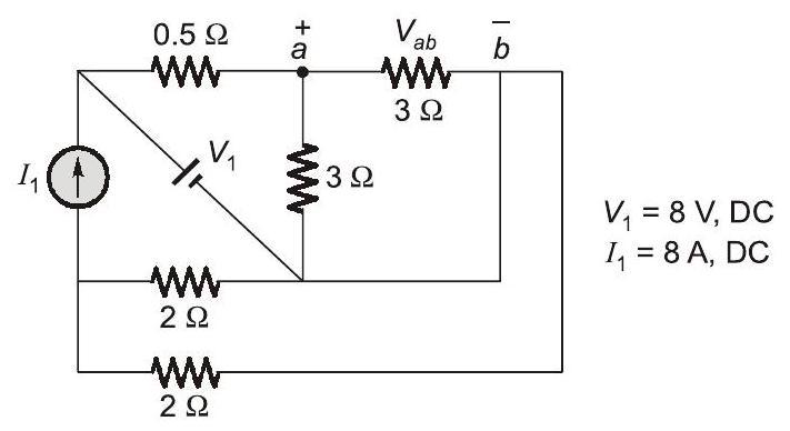
IncorrectFor the circuit shown in the figure, and . The voltage in Volts is __________ (Round off to 1 decimal place).



Sign in to see the solution
Log in to view the explanation, track your attempts, and keep your progress.
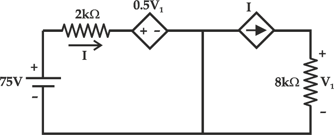
Sign in to UnlockIn the circuit shown below, the magnitude of voltage V1 in volts, across the 8 kΩ resistor is ________ . (round off to nearest integer)
Sign in to see the solution
Log in to view the explanation, track your attempts, and keep your progress.
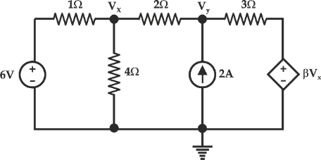
Sign in to UnlockIn the given circuit, for voltage Vy to be zero, value of β should be_________ (round off to 2 decimal places).
Sign in to see the solution
Log in to view the explanation, track your attempts, and keep your progress.
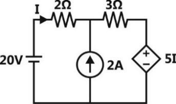
Sign in to UnlockThe current I flowing in the circuit shown below in amperes (round off to one decimal place) is ____________.
Sign in to see the solution
Log in to view the explanation, track your attempts, and keep your progress.
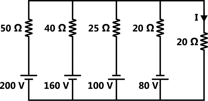
Sign in to UnlockThe current I flowing in the circuit shown below in amperes is ________.
Sign in to see the solution
Log in to view the explanation, track your attempts, and keep your progress.
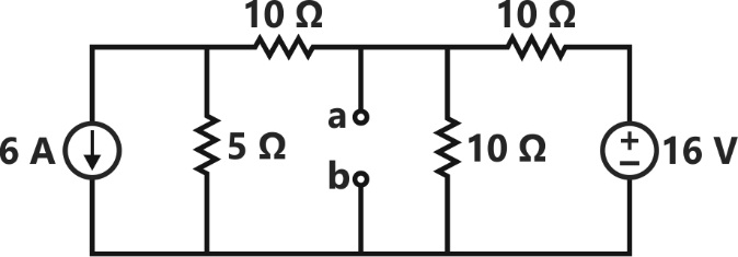
Sign in to UnlockFor the network given in figure below, the Thevenin’s voltage Vab is
Sign in to see the solution
Log in to view the explanation, track your attempts, and keep your progress.
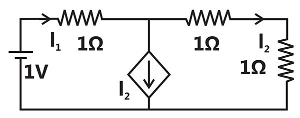
Sign in to UnlockIn the given circuit, the current supplied by the battery, in ampere, is______________
Sign in to see the solution
Log in to view the explanation, track your attempts, and keep your progress.
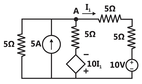
Sign in to UnlockIn the circuit shown below, the node voltage is ________________V.

Sign in to see the solution
Log in to view the explanation, track your attempts, and keep your progress.
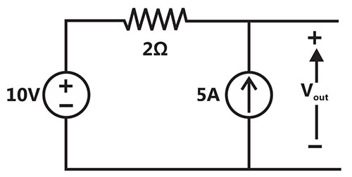
Sign in to UnlockIn the circuit shown below, the voltage and current sources are ideal. The voltage across the current source, in volts, is

Sign in to see the solution
Log in to view the explanation, track your attempts, and keep your progress.
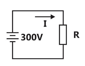
Sign in to UnlockIn the figure, the value of resistor R is (25 + I/2) ohms, where I is the current in amperes. The current I is ________________.
Sign in to see the solution
Log in to view the explanation, track your attempts, and keep your progress.
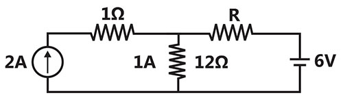
Sign in to UnlockIf the resistor draws a current of 1 A as shown in the figure, the value of resistance R is





Sign in to see the solution
Log in to view the explanation, track your attempts, and keep your progress.
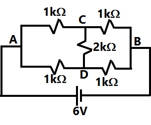
Sign in to UnlockThe current through the 2kΩ resistance in the circuit shown is
Sign in to see the solution
Log in to view the explanation, track your attempts, and keep your progress.
Sign in to UnlockIn the circuit shown in the figure. The value of the current i will be given by
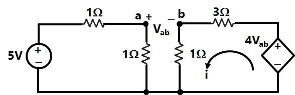
Sign in to see the solution
Log in to view the explanation, track your attempts, and keep your progress.
Sign in to UnlockA 3 V dc supply with an internal resistance of 2Ω supplies a passive non-linear resistance characterized by the relation. The power dissipated in the non linear resistance is

Sign in to see the solution
Log in to view the explanation, track your attempts, and keep your progress.
Sign in to UnlockFigure the value of R is
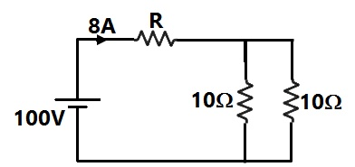
Sign in to see the solution
Log in to view the explanation, track your attempts, and keep your progress.
Sign in to UnlockIn figure, the value of the source voltage is
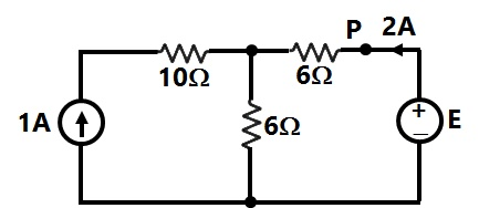
Sign in to see the solution
Log in to view the explanation, track your attempts, and keep your progress.
Sign in to UnlockIn figure, the value of resistance R in Ω is
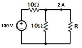
Sign in to see the solution
Log in to view the explanation, track your attempts, and keep your progress.
Sign in to UnlockIn Figure, the potential difference between points P and Q is
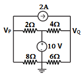
Sign in to see the solution
Log in to view the explanation, track your attempts, and keep your progress.
Sign in to UnlockIn Figure the value of R is
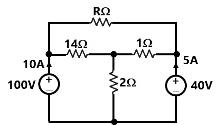
Sign in to see the solution
Log in to view the explanation, track your attempts, and keep your progress.
Sign in to UnlockIn the resistor network shown in Figure, all resistor values are 1Ω. A current of 1A passes from terminal a to terminal b, as shown in the figure. Calculate the voltage between terminals a and b. [Hint: You may exploit the symmetry of the circuit].
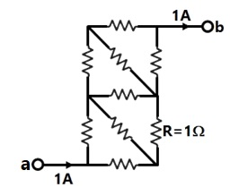
Sign in to see the solution
Log in to view the explanation, track your attempts, and keep your progress.
Sign in to UnlockSolve the circuit shown in figure using the mesh method of analysis and determine the mesh currents and . Evaluate the power developed in the 10V voltage source.


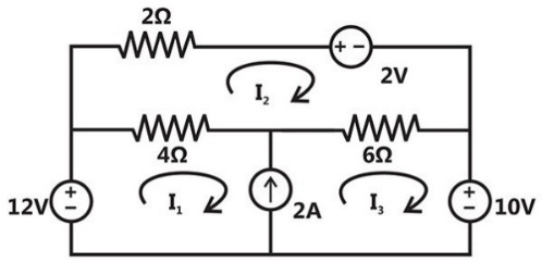
Sign in to see the solution
Log in to view the explanation, track your attempts, and keep your progress.
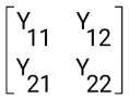
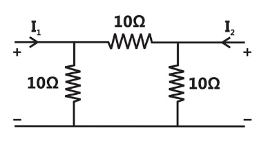
Sign in to UnlockFor the two port network shown in figure, the admittance matrix is . Then Find
\(Y_{11} + Y_{12} + Y_{22} + Y_{21} = ?\)
Sign in to see the solution
Log in to view the explanation, track your attempts, and keep your progress.
Sign in to UnlockA 10V battery with an internal resistance of 1Ω is connected across a nonlinear load whose V-I characteristic is given by . The current delivered by the battery is __________ A

Sign in to see the solution
Log in to view the explanation, track your attempts, and keep your progress.
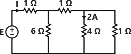
Sign in to UnlockThe values of E and I for the circuit shown in figure, are_________V and _________A. Then E+I= ?
Sign in to see the solution
Log in to view the explanation, track your attempts, and keep your progress.
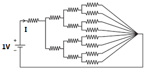
Sign in to UnlockAll the resistances in figure are each. The value of current ‘I’ is





Sign in to see the solution
Log in to view the explanation, track your attempts, and keep your progress.
Sign in to Unlock