Power Electronics
Phase Controlled Converter
Practice questions from Phase Controlled Converter.
82
Total0
Attempted0
Correct0
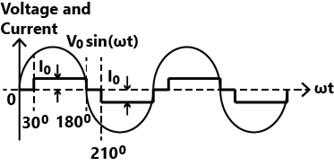
IncorrectThe input voltage and current of a converter are given by,


where, . The input power factor of the converter is closest to

Explanation Locked!
Unlock this branch to view the explanation, track, bookmark and more.
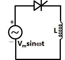
Sign in to Unlockfeeds an ideal inductor through an ideal SCR with firing angle . If , then the peak of the inductor current, in ampere, is closest to


Explanation Locked!
Unlock this branch to view the explanation, track, bookmark and more.
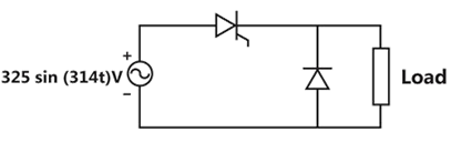
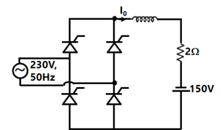
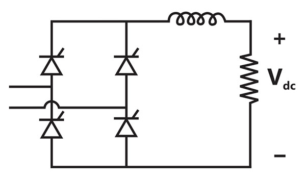
Sign in to UnlockIn the following circuit, the average voltage

where is the firing angle. If the power dissipated in the resistor is 64 W, then the closest value of in degrees is

Explanation Locked!
Unlock this branch to view the explanation, track, bookmark and more.
Sign in to UnlockA single-phase half-controlled bridge converter supplies an inductive load with ripple free load current. The triggering angle of the converter is . The ratio of the rms value of the fundamental component of the input current to the rms value of the total input current of the bridge is ________ (rounded off to 3 decimal places).

Explanation Locked!
Unlock this branch to view the explanation, track, bookmark and more.
Sign in to UnlockA single-phase full-controlled thyristor converter bridge is used for regenerative braking of a separately excited DC motor with the following specifications:
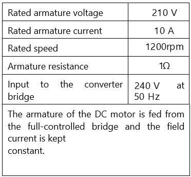
Assume that the motor is running at 600rpm and the armature terminals of the motor are suitably reversed for regenerative braking. If the armature current of the motor is to be maintained at the rated value, the triggering angle of the converter bridge in degrees should be ________ (rounded off to 2 decimal places).
Explanation Locked!
Unlock this branch to view the explanation, track, bookmark and more.
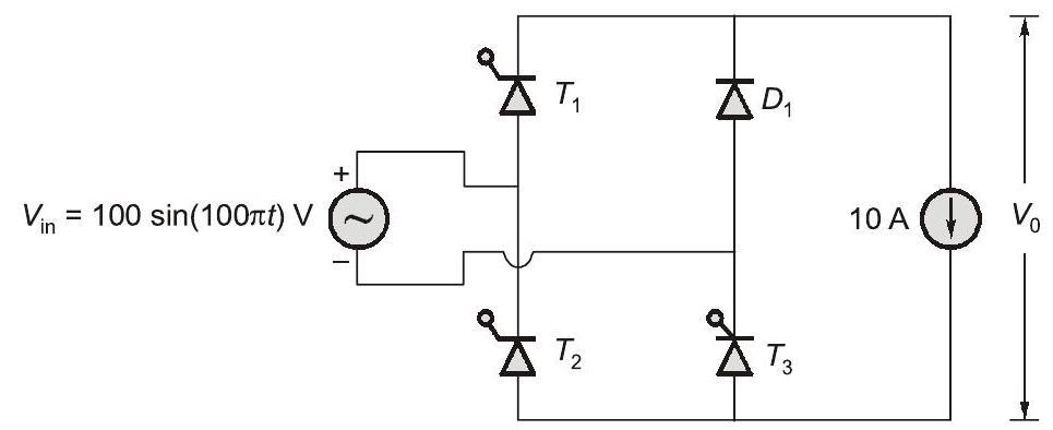
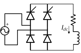
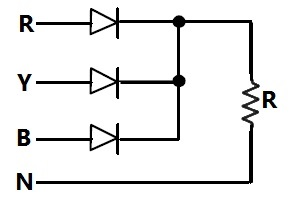
Sign in to UnlockThe single phase rectifier consisting of three thyristors and a diode feed power to a constant current load. and are fired at α=60° and is fired at α=240° . The reference for is the positive zero crossing of . The average voltage across the load in volts is ________ (Round off to 2 decimal places).


Explanation Locked!
Unlock this branch to view the explanation, track, bookmark and more.
Sign in to UnlockA single-phase full-bridge diode rectifier feeds a resistive load of 50 Ω from a 200 V, 50 Hz single phase AC supply. If the diodes are ideal, then the active power, in watts, drawn by the load is _____________. (round off to nearest integer).
Explanation Locked!
Unlock this branch to view the explanation, track, bookmark and more.
Sign in to UnlockThe voltage at the input of an AC-DC rectifier is given by where ω = 2π × 50 rad/s. The input current drawn by the rectifier is given by .


The input power factor, (rounded off to two decimal places), is, _________________ lag.
Explanation Locked!
Unlock this branch to view the explanation, track, bookmark and more.
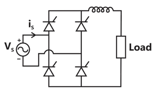
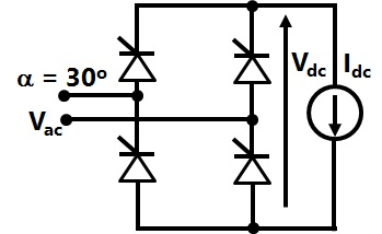
Sign in to UnlockFor the ideal AC-DC rectifier circuit shown in the figure below, the load current magnitude is and is ripple free. The thyristors are fired with a delay angle of 45°. The amplitude of the fundamental component of the source current, in amperes, is __________. (round off to two decimal places)

Explanation Locked!
Unlock this branch to view the explanation, track, bookmark and more.
Sign in to UnlockA single-phase, full-bridge, fully controlled thyristor rectifier feeds a load comprising a 10 Ω resistance in series with a very large inductance. The rectifier is fed from an ideal 230 V, 50 Hz sinusoidal source through cables which have negligible internal resistance and a total inductance of 2.28 mH. If the thyristors are triggered at an angle , the commutation overlap angle in degree (rounded off to 2 decimal places) is ______.

Explanation Locked!
Unlock this branch to view the explanation, track, bookmark and more.
Sign in to UnlockA six-pulse thyristor bridge rectifier is connected to a balanced three-phase, 50 Hz AC source. Assuming that the DC output current of the rectifier is constant, the lowest harmonic component in the AC input current is
Explanation Locked!
Unlock this branch to view the explanation, track, bookmark and more.
Sign in to UnlockA single-phase fully-controlled thyristor converter is used to obtain an average voltage of 180 V with 10 A constant current to feed a DC load. It is fed from single-phase AC supply of 230 V, 50 Hz. Neglect the source impedance. The power factor (round off to two decimal places) of AC mains is ________.
Explanation Locked!
Unlock this branch to view the explanation, track, bookmark and more.
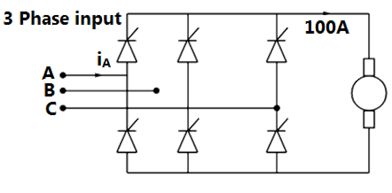
Sign in to UnlockA fully-controlled three-phase bridge converter is working from a 415 V, 50 Hz AC supply. It is supplying constant current of 100 A at 400 V to a DC load. Assume larger inductive smoothing and neglect overlap. The rms value of the AC line current in amperes (round off to two decimal places) is _________.
Explanation Locked!
Unlock this branch to view the explanation, track, bookmark and more.
Sign in to UnlockA single-phase, full-bridge diode rectifier fed from a 230 V, 50 Hz sinusoidal source supplies a series combination of finite resistance. R, and a very large inductance, L. The two most dominant frequency components in the source current are:
Explanation Locked!
Unlock this branch to view the explanation, track, bookmark and more.
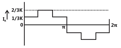
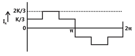
Sign in to UnlockThe waveform of the current drawn by a semi-converter from a sinusoidal AC voltage I source is shown in the figure. If , the RMS value of fundamental component of the current is _______ A (up to 2 decimal places).

Explanation Locked!
Unlock this branch to view the explanation, track, bookmark and more.
Sign in to UnlockA single phase fully controlled rectifier is supplying a load with an anti-parallel diode as shown in the figure. All switches and diodes are ideal. Which one of the following is true for instantaneous load voltage and current?

&


&

&

&
Explanation Locked!
Unlock this branch to view the explanation, track, bookmark and more.
Sign in to UnlockA phase controlled signal phase reflector, supplied by an AC source, feeds power to an R-L-E load as shown in the figure. The reflector output voltage has an average value given by , where and is the firing angle. If the power delivered to the loss less battery is 1600W, in degree is ______ (up to 2 decimal places)


Explanation Locked!
Unlock this branch to view the explanation, track, bookmark and more.
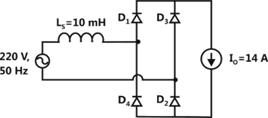
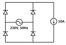
Sign in to UnlockThe figure below shows an uncontrolled diode bridge rectifier supplied from a 220 V, 50 Hz, 1-phase ac source. The load draws a constant current . The conduction angle of the diode in degrees (rounded off to two decimal places) is ____________.


Explanation Locked!
Unlock this branch to view the explanation, track, bookmark and more.
Sign in to UnlockIn the circuit shown, the diodes are ideal, the inductance is small, and . Which one of the following statements is true?

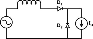
conducts for greater than 180° and conducts for greater than 180°.

conducts for more than 180° and conducts for 180°.
conducts for 180° and conducts for 180°.
conducts for more than 180° and conducts for 180°.
Explanation Locked!
Unlock this branch to view the explanation, track, bookmark and more.
Sign in to UnlockThe figure below shows the circuit diagram of a controlled rectifier supplied from a 230 V, 50 Hz, 1-phase voltage source and a 10:1 ideal transformer. Assume that all devices are ideal. The firing angles of the thyristors and are 90° and 270°, respectively.


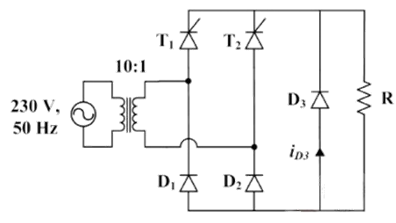
The RMS value of the current though diode in amperes is ___________.

Explanation Locked!
Unlock this branch to view the explanation, track, bookmark and more.
Sign in to UnlockA phase-controlled, single-phase, full-bridge converter is supplying a highly inductive DC load. The converter is fed from a 230 V, 50 Hz, AC source. The fundamental frequency in Hz of the voltage ripple on the DC side is
Explanation Locked!
Unlock this branch to view the explanation, track, bookmark and more.
Sign in to UnlockIn the circuit shown in the figure, the diode used is ideal. The input power factor is ___________ . (Give the answer up to two decimal places)
Explanation Locked!
Unlock this branch to view the explanation, track, bookmark and more.
Sign in to UnlockA single-phase thyristor-bridge rectifier is fed from a 230V, 50Hz, single-phase AC mains. If it is delivering a constant DC current of 10A, at firing angle of , then value of the power factor at AC mains is

Explanation Locked!
Unlock this branch to view the explanation, track, bookmark and more.
Sign in to UnlockA three-phase diode bridge rectifier is feeding a constant DC current of 100A to a highly inductive load. If three-phase, 415V, 50Hz AC source is supplying to this bridge rectifier then the rms value of the current in each diode, in ampere, is________________.
Explanation Locked!
Unlock this branch to view the explanation, track, bookmark and more.
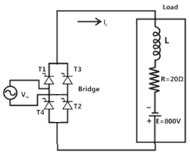
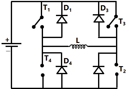
Sign in to UnlockA full-bridge converter supplying an RLE load is shown in figure. The firing angle of the bridge converter is . The supply voltage . . The inductor L is large enough to make the output current a smooth dc current. Switches are lossless. The real power fed back to the source, in kW, is____________.


Explanation Locked!
Unlock this branch to view the explanation, track, bookmark and more.
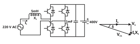
Sign in to UnlockA single-phase bi-directional voltage source converter (VSC) is shown in the figure below. All devices are ideal. It is used to charge a battery at 400V with power of 5kW from a source V (rms), 50Hz sinusoidal AC mains at unity p.f. If its AC side interfacing inductor is 5mH and the switches are operated at 20kHz, then the phase shift between AC mains voltage and fundamental AC rms VSC voltage , in degrees, is_____.


Explanation Locked!
Unlock this branch to view the explanation, track, bookmark and more.
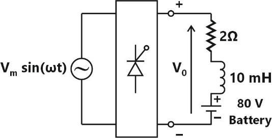
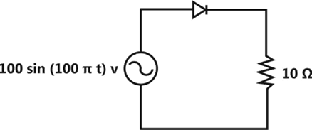
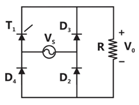
Sign in to UnlockIn the given rectifier, the delay angle of the thyristor measured from the positive going zero crossing of is . If the input voltage is V, the average voltage across R (in Volt) under steady-state is __________.


Explanation Locked!
Unlock this branch to view the explanation, track, bookmark and more.
Sign in to UnlockThe figure shows the circuit of a rectifier fed from a 230 – V (rms), 50 – Hz sinusoidal voltage source. If we want to replace the current source with a resistor so that the rms value of the current supplied by the voltage source remains unchanged, the value of the resistance (in ohms) is _________ (Assume diodes to be ideal)
Explanation Locked!
Unlock this branch to view the explanation, track, bookmark and more.
Sign in to UnlockThe figure shows the circuit diagram of the rectifier. The load consists of a reactance and an inductance 0.05H connected in series. Assuming ideal thyristor and ideal diode, the thyristor firing angle (in degree) needed to obtain an average load voltage of 70V is_____________

Explanation Locked!
Unlock this branch to view the explanation, track, bookmark and more.
Sign in to UnlockA fully controlled converter bridge feeds a highly inductive load with ripple free load current. The input supply to the bridge is a sinusoidal source. Triggering angle of the bridge converter is . The input power factor of the bridge is _____________.


Explanation Locked!
Unlock this branch to view the explanation, track, bookmark and more.
Sign in to UnlockA three-phase fully controlled bridge converter is fed through star-delta transformer as shown in the figure.
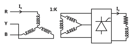
The converter is operated at a firing angle of , Assuming the load current to be virtually constant at 1p.u. and transformer to be an ideal one, the input phase current waveform is

Explanation Locked!
Unlock this branch to view the explanation, track, bookmark and more.
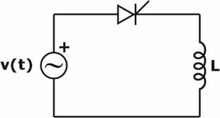
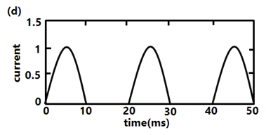
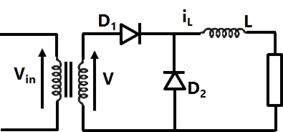
Sign in to UnlockA diode circuit feeds an ideal inductor as shows in the figure, Given , where , and L = 31.83 mH. The initial value of inductor current is zero. Switch S is closed at t = 2.5ms. The peak value of inductor current (in (a) in the first cycle is ____________.


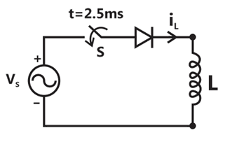
Explanation Locked!
Unlock this branch to view the explanation, track, bookmark and more.
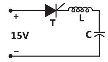
Sign in to UnlockThyristor T in the figure below is initially off and is triggered with a single pulse of width 10μs. It is given that and. Assuming latching and holding currents of the thyristor are both zero and the initial charge on C is zero, T conducts for


Explanation Locked!
Unlock this branch to view the explanation, track, bookmark and more.
Sign in to UnlockA half-controlled single-phase bridge rectifier is supplying an R-L load. It is operated at a firing angle and the load current is continuous. The fraction of cycle that the freewheeling diode conducts is

1/2


Explanation Locked!
Unlock this branch to view the explanation, track, bookmark and more.
Sign in to UnlockThe input voltage given to a converter is

The current drawn by the converter is

The input power factor of the converter is
Explanation Locked!
Unlock this branch to view the explanation, track, bookmark and more.
Sign in to UnlockThe input voltage given to a converter is
The current drawn by the converter is
The active power drawn by the converter is
Explanation Locked!
Unlock this branch to view the explanation, track, bookmark and more.
Sign in to UnlockA solar energy installation utilizes a three-phase bidge converter to feed energy into power system through a transformer of 400V/400V, as shown below.
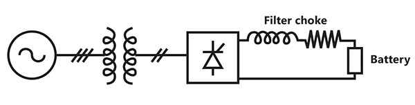
The energy is collected in a bank of 400V batteries and is connected to converter through a large filter choke of resistance.
The maximum current through the battery will be
Explanation Locked!
Unlock this branch to view the explanation, track, bookmark and more.
Sign in to UnlockA solar energy installation utilizes a three-phase bidge converter to feed energy into power system through a transformer of 400V/400V, as shown below.
The energy is collected in a bank of 400V batteries and is connected to converter through a large filter choke of resistance.
The kVA rating of the input transformer is
Explanation Locked!
Unlock this branch to view the explanation, track, bookmark and more.
Sign in to UnlockThe fully controlled thyristor converter in the figure is fed from a single-phase source. When the firing angle is, the dc output voltage of the converter is 300V. What will be the output voltage for a firing angle of , assuming continuous conduction?


150V
210V
300V

Explanation Locked!
Unlock this branch to view the explanation, track, bookmark and more.
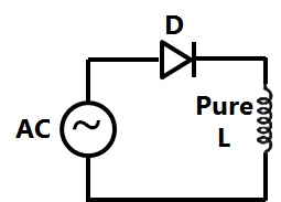
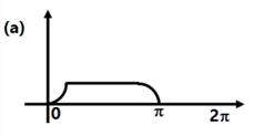
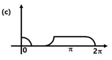
Sign in to UnlockThe circuit shows an ideal diode connected to a pure inductor and is connected to a purely sinusoidal 50Hz voltage source. Under Ideal conditions the current waveform through the inductor will look like

Explanation Locked!
Unlock this branch to view the explanation, track, bookmark and more.
Sign in to UnlockA single phase fully controlled bridge converter supplies a load drawing constant and ripple free load current. If the triggering angle is 30°, the input power factor will be
Explanation Locked!
Unlock this branch to view the explanation, track, bookmark and more.
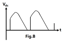
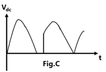
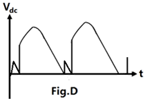
Sign in to UnlockA single-phase half controlled converter shown in the figure is feeding power to highly inductive load. The converter is operating at a firing angle of 60°.
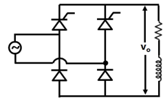
If the firing pulses are suddenly removed, the steady state voltage waveform of the converter will become

Explanation Locked!
Unlock this branch to view the explanation, track, bookmark and more.
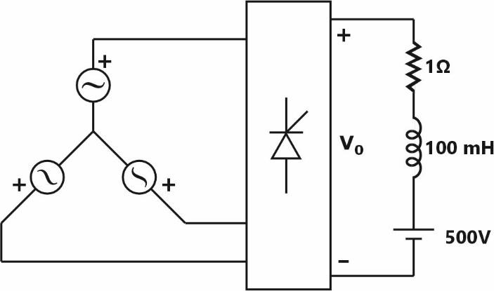
Sign in to UnlockA single phase fully controlled converter bridge is used for electrical braking of a separately excited dc motor. The dc motor load is represented by an equivalent circuit as shown in the figure. Assume that the load inductance is sufficient to ensure continuous and ripple free load current. The firing angle of the bridge for a load current will be


Explanation Locked!
Unlock this branch to view the explanation, track, bookmark and more.
Sign in to UnlockA three phase fully controlled bridge converter is feeding a load drawing a constant and ripple free load current of 10A at a firing angle of 30°. The approximate Total Harmonic Distortion (%THD) and the RMS value of fundamental component of the input current will respectively be
Explanation Locked!
Unlock this branch to view the explanation, track, bookmark and more.
Sign in to UnlockA single-phase fully controlled thyristor bridge ac-dc converter is operating at a firing angle of 25° and an overlap angle of 10° with constant dc output current of 20 A. The fundamental power factor (displacement factor) al input ac mains is
Explanation Locked!
Unlock this branch to view the explanation, track, bookmark and more.
Sign in to UnlockA three-phase, fully-controlled thyristor bridge converter is used as line commutated inverter to feed 50 kW power at 420 V dc to a three-phase, 415V (line), 50 Hz ac mains. Consider dc link current to be constant. The RMS Current of the thyristor is
Explanation Locked!
Unlock this branch to view the explanation, track, bookmark and more.
Sign in to UnlockA single phase full-wave half-controlled bridge convener feeds an inductive load. The two SCRs in the converter are connected to a common DC bus. The converter has to have a freewheeling diode
Explanation Locked!
Unlock this branch to view the explanation, track, bookmark and more.
Sign in to UnlockA three-phase, 440 V, 50 Hz ac mains fed thyristor bridge is feeding a 440 V dc, 15 kW, 1500 rpm separately excited dc motor with a ripple free continuous current in the dc link under all operating conditions. Neglecting the losses, the power factor of the ac mains at half the rated speed, is
Explanation Locked!
Unlock this branch to view the explanation, track, bookmark and more.
Sign in to UnlockA single-phase, 230V, 50 Hz ac mains fed step down transformer (4:1) is supplying power to a half-wave uncontrolled ac-dc converter used for charging a battery (12 V dc) with the series current limiting resistor being 19.04 Ω. The charging current is
Explanation Locked!
Unlock this branch to view the explanation, track, bookmark and more.
Sign in to UnlockIn the circuit of adjacent figure the diode connects the ac source to a pure inductance L.
The diode conducts for
Explanation Locked!
Unlock this branch to view the explanation, track, bookmark and more.
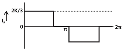
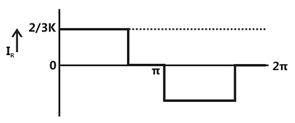
Sign in to UnlockA single-phase half wave uncontrolled converter circuit is shown in figure. A 2-winding transformer is used at the input for isolation. Assuming the load current to be constant and, the current waveform through diode will be


Explanation Locked!
Unlock this branch to view the explanation, track, bookmark and more.
Sign in to UnlockA 3-phase fully controlled bridge converter with freewheeling diode is fed from 400 V, 50 Hz AC source and is operating at a firing angle of 60°. The load current is assumed constant at 10A due to high load inductance. The input displacement factor (IDF) and the input power factor (IPF) of the converter will be
Explanation Locked!
Unlock this branch to view the explanation, track, bookmark and more.
Sign in to UnlockA solar cell of 350 V is feeding power to an ac supply of 440V, 50 Hz through a 3-phase fully controlled bridge converter. A large inductance is connected in the dc circuit to maintain the dc current at 20A. If the solar cell resistance is 0.5Ω, then each thyristor will be reverse biased for a period of
Explanation Locked!
Unlock this branch to view the explanation, track, bookmark and more.
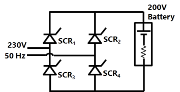
Sign in to UnlockA single-phase bridge converter is used to charge a battery of 200V having an internal resistance of 2Ω as shown in figure. The SCR’s are triggered by a constant dc signal. If SCR 2 gets open circuited, then what will be average charging current?
Explanation Locked!
Unlock this branch to view the explanation, track, bookmark and more.
Sign in to UnlockA three-phase diode bridge rectifier is fed from a 400V RMS, 50 Hz, three-phase AC source. If the load is purely resistive, the peak instantaneous output voltage is equal to
400 V
V

V

V

Explanation Locked!
Unlock this branch to view the explanation, track, bookmark and more.
Sign in to UnlockThe circuit in figure shows a 3-phase half-wave rectifier. The source is a symmetrical, 3-phase four-wire system. The line-to-line voltage of the source is 100 V. The supply frequency is 400 Hz. The ripple frequency at the output is
Explanation Locked!
Unlock this branch to view the explanation, track, bookmark and more.
Sign in to UnlockA single-phase half wave controlled rectifier is driving a separately excited dc motor. The dc motor has a back emf constant of 0.5 V/rpm. The armature current is 5A without any ripple. The armature resistance is 2Ω.
The converter is working from a 230 V, single-phase ac source with a firing angle of 30°. Under this operating condition, the speed of the motor will be
Explanation Locked!
Unlock this branch to view the explanation, track, bookmark and more.
Sign in to UnlockA fully controlled natural commuted 3-phase bridge rectifier is operating with a firing angle α=30°. The peak to peak voltage ripple expressed as a ratio of the peak output dc voltage at the output of the converter bridge is
0.5


Explanation Locked!
Unlock this branch to view the explanation, track, bookmark and more.
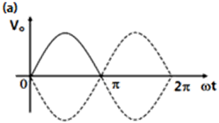
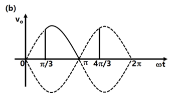
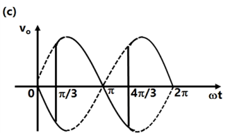
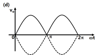
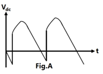
Sign in to UnlockA phase controlled half controlled single phase converter is
shown in Figure. The control angle
α = 30°. The output dc voltage wave shape will be a s shown in
Explanation Locked!
Unlock this branch to view the explanation, track, bookmark and more.
Sign in to UnlockIn the single phase diode bridge rectifier shown in figure, the load resistor is R = 50Ω.
The source voltage is v=200sin(ωt), where ω=2π × 50 radians per second. The power dissipated in the load resistor R is


400 W
800 W
Explanation Locked!
Unlock this branch to view the explanation, track, bookmark and more.
Sign in to UnlockA six pulse thyristor rectifier bridge is connected to a balanced 50 Hz three phase ac source. Assuming that the dc output current of the rectifier is constant, the lowest frequency harmonic component in the ac source line current is
Explanation Locked!
Unlock this branch to view the explanation, track, bookmark and more.
Sign in to UnlockA three phase thyristor bridge rectifier is used in a HVDC link. The firing angle α (as measured from the point of natural commutation) is constrained to lie between 5° and 30°. If the dc side current and ac side voltage magnitudes are constant, which of the following statements is true (neglect harmonics in the ac side currents and commutation overlap in your analysis)
Explanation Locked!
Unlock this branch to view the explanation, track, bookmark and more.
Sign in to UnlockAC-to-DC circulating current dual converters is operated with the following relationship between their triggering angles ( and ).


Explanation Locked!
Unlock this branch to view the explanation, track, bookmark and more.
Sign in to UnlockA half-wave thyristor converter supplies a purely inductive load, as shown in Figure. If the triggering angle of the thyristor is 120°, the extinction angle will be
Explanation Locked!
Unlock this branch to view the explanation, track, bookmark and more.
Sign in to UnlockA single-phase full bridge voltage source inverter feeds a purely inductive load, as shown in figure, where , , , are power transistors and , , , are feedback diodes. The inverter is operated in square-wave mode with a frequency of 50 Hz. If the average load current is zero, what is the time duration of conduction of each feedback diode in a cycle?


Explanation Locked!
Unlock this branch to view the explanation, track, bookmark and more.
Sign in to UnlockA three phase semi-converter feeds the armature of a separately excited dc motor, supplying a non-zero torque. For steady state operation, the motor armature current is found to drop to zero at certain instances of time. At such instances, the voltage assumes a value that is
Explanation Locked!
Unlock this branch to view the explanation, track, bookmark and more.
Sign in to UnlockA thyristor, three phase, fully controlled converter feeds a dc load that draws a constant current. Then the input ac line current to the converter has
Explanation Locked!
Unlock this branch to view the explanation, track, bookmark and more.
Sign in to UnlockResonant converters are basically used to
Explanation Locked!
Unlock this branch to view the explanation, track, bookmark and more.
Sign in to UnlockA three phase diode bridge is used to provide rectified output from a 400V, 50Hz, 3-phase supply to a R-L load with 10 Ω resistance and 300mH inductance.
Explanation Locked!
Unlock this branch to view the explanation, track, bookmark and more.
Sign in to UnlockWhen the firing angle α of a single phase, fully controlled rectifier feeding constant d.c. current into a load is 30°, the displacement power factor of the rectifier is:
1
0.5

Explanation Locked!
Unlock this branch to view the explanation, track, bookmark and more.
Sign in to UnlockA 3-phase, fully controlled, converter is feeding power into a d.c. load at a constant current of 150A. The rms current through each thyristor of the converter is:
50A
100A


Explanation Locked!
Unlock this branch to view the explanation, track, bookmark and more.
Sign in to UnlockA d.c. motor driven from a fully controlled 3 phase converter shown in figure, draws a d.c. current of 100A with negligible ripple.
(a) Sketch the a.c. line current for one cycle

(b) Determine the 3rd and 5th harmonic components of the line current as a percentage of the fundamental current
Third harmonic current as a percentage of Fundamental current = 0%
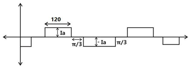
Fifth harmonic current as a percentage of Fundamental current =20%
Third harmonic current as a percentage of Fundamental current = 10%
Explanation Locked!
Unlock this branch to view the explanation, track, bookmark and more.
Sign in to UnlockIn a dual converter, the circulating current
Explanation Locked!
Unlock this branch to view the explanation, track, bookmark and more.
Sign in to UnlockAn SCR is connected in series with a 300V ac supply and a 300 ohms load resistor. Calculate for a firing angle of 45°
- The reading of a moving coil ammeter connected in series with the load and
- The reading on a moving iron voltmeter connected across the SCR
Explanation Locked!
Unlock this branch to view the explanation, track, bookmark and more.
Sign in to UnlockIn a 3-phase controlled bridge rectifier, with an increase of overlap angle, the output dc voltage
Explanation Locked!
Unlock this branch to view the explanation, track, bookmark and more.
Sign in to UnlockA single phase diode bridge rectifier supplies a highly inductive load. The load current can be assumed to be ripple free. The ac supply side current waveform will be:
Explanation Locked!
Unlock this branch to view the explanation, track, bookmark and more.
Sign in to UnlockA three phase ac-to-dc diode bridge rectifier is supplied from a three-phase, 440V source. The rectifier supplies a purely resistive load. The average dc voltage across the load will be ________________V.
Explanation Locked!
Unlock this branch to view the explanation, track, bookmark and more.
Sign in to UnlockThe single phase half controlled ac to dc bridge converter of figure supplies a 10 Ohm resistor in series with a 100V back emf load. The firing angle of the thyristors is set to 60°
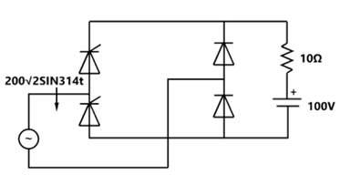
(i) Find the average current through the resistor
(ii) What will be the new average current through the resistor, if a very large inductor is connected in series with the load?
Explanation Locked!
Unlock this branch to view the explanation, track, bookmark and more.
Sign in to UnlockReferring to the figure the type of load is
Explanation Locked!
Unlock this branch to view the explanation, track, bookmark and more.
Sign in to UnlockA line-commutated inverter changes dc voltage to ac voltage. (True=1/False=0)
Explanation Locked!
Unlock this branch to view the explanation, track, bookmark and more.
Sign in to UnlockThe output voltage of a six-pulse double star rectifier is the same as that of a three-phase half- wave rectifier. (True=1/False=0)
Explanation Locked!
Unlock this branch to view the explanation, track, bookmark and more.
Sign in to UnlockWhen a line commutated converter operates in the inverter mode
Explanation Locked!
Unlock this branch to view the explanation, track, bookmark and more.
Sign in to Unlock