Power Electronics
Power Semiconductor Devices
Triggering and Characteristics of SCR
Questions mapped to Triggering and Characteristics of SCR under Power Semiconductor Devices.
14
Total0
Attempted0
Correct0
IncorrectConsider the circuit shown in Figure (a). A gate pulse is applied between time instants and . After , during the MOSFET turn OFF process, it experiences a voltage overshoot.



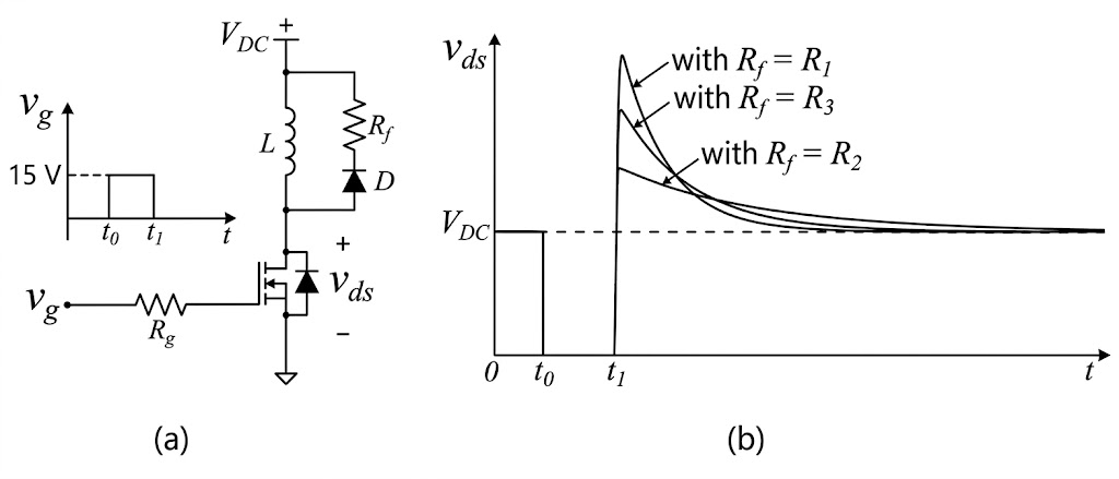
Based on the waveforms shown in Figure (b), which one of the following options is correct?





Sign in to see the solution
Log in to view the explanation, track your attempts, and keep your progress.
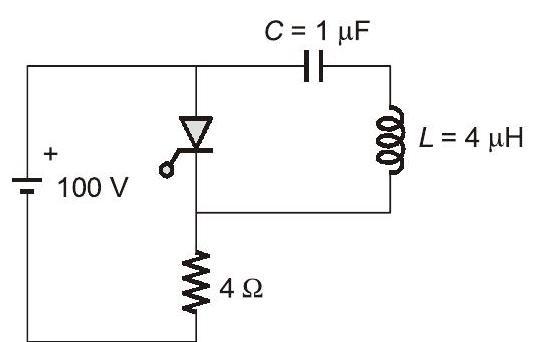
Sign in to UnlockThe circuit shown in the figure has reached steady state with thyristor '' in OFF condition. Assume that the latching and holding currents of the thyristor are zero. The thyristor is turned at . The duration in microseconds for which the thyristor would conduct, before it turns off, is ___ (Round off to 2 decimal places).



Sign in to see the solution
Log in to view the explanation, track your attempts, and keep your progress.
Sign in to UnlockThe SCR in the circuit shown has a latching current of 40mA. A gate pulse of 50 μs is applied to the SCR. The maximum value of R in to ensure successful firing of the SCR is ___________.


Sign in to see the solution
Log in to view the explanation, track your attempts, and keep your progress.
Sign in to UnlockThe typical ratio of latching current to holding current in a 20A thyristor is
Sign in to see the solution
Log in to view the explanation, track your attempts, and keep your progress.
Sign in to UnlockAn SCR is considered to be a semi-controlled device because
Sign in to see the solution
Log in to view the explanation, track your attempts, and keep your progress.
Sign in to UnlockA 1:1 Pulse Transformer (PT) is used to trigger the SCR in the adjacent figure. The SCR is rated at 1.5 kV,250A with 250mA, 150mA, and 150mA, 100mA. The SCR is connected to an inductive load, where L = 150mH in series with a small resistance and the supply voltage is 200V dc. The forward drops of all transistors/diodes and gate-cathode junction during ON state are 1.0 V




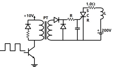
The resistance R should be
Sign in to see the solution
Log in to view the explanation, track your attempts, and keep your progress.
Sign in to UnlockA 1:1 Pulse Transformer (PT) is used to trigger the SCR in the adjacent figure. The SCR is rated at 1.5 kV,250A with 250mA, 150mA, and 150mA, 100mA. The SCR is connected to an inductive load, where L = 150mH in series with a small resistance and the supply voltage is 200V dc. The forward drops of all transistors/diodes and gate-cathode junction during ON state are 1.0 V
The minimum approximate volt-second rating of the pulse transformer suitable for triggering the SCR should be: (volt-second rating is the maximum of product of the voltage and the width of the pulse that may be applied)
Sign in to see the solution
Log in to view the explanation, track your attempts, and keep your progress.
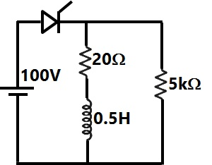
Sign in to UnlockAn SCR having a turn ON time of 5µsec, latching current of 50mA and holding current of 40mA is triggered by a short duration pulse and is used in the circuit shown in figure. The minimum pulse width required to turn the SCR ON will be
Sign in to see the solution
Log in to view the explanation, track your attempts, and keep your progress.
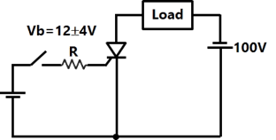
Sign in to UnlockThe triggering circuit of a thyristor is shown in figure. The thyristor requires a gate current of 10 mA, for guaranteed turn-on. The value of R required for the thyristor to turn on reliably under all conditions of variation is

Sign in to see the solution
Log in to view the explanation, track your attempts, and keep your progress.
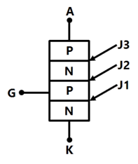
Sign in to UnlockFigure shows a thyristor with the standard terminations of anode (A), cathode (K), gate (G) and the different junctions named J1, J2 and J3. When the thyristor is turned on and conducting
Sign in to see the solution
Log in to view the explanation, track your attempts, and keep your progress.
Sign in to UnlockThe main reason for connecting a pulse transformer at the output stage of a thyristor triggering circuit is to
Sign in to see the solution
Log in to view the explanation, track your attempts, and keep your progress.
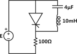
Sign in to UnlockConsider the thyristor circuit of figure. The Thyristor is given a triggering pulse after every 10ms. Calculate the duration for which the thyristor remains ON after each triggering pulse. Assume ideal devices and explain briefly the basis.
Sign in to see the solution
Log in to view the explanation, track your attempts, and keep your progress.
Sign in to UnlockA triac can be triggered by a gate pulse of ______________ polarity.
Sign in to see the solution
Log in to view the explanation, track your attempts, and keep your progress.
Sign in to UnlockThe operating state that distinguishes a silicon controlled rectifier (SCR) from a diode is
Sign in to see the solution
Log in to view the explanation, track your attempts, and keep your progress.
Sign in to Unlock