Power Systems
Power System Protection
Overcurrent Protection
Questions mapped to Overcurrent Protection under Power System Protection.
7
Total0
Attempted0
Correct0
IncorrectFor the three-bus power system shown in the figure, the trip signals to the circuit breakers to are provided by overcurrent relays to , respectively, some of which have directional properties also. The necessary condition for the system to be protected for short circuit fault at any part of the system between bus 1 and the - loads with isolation of minimum portion of the network using minimum number of directional relays is






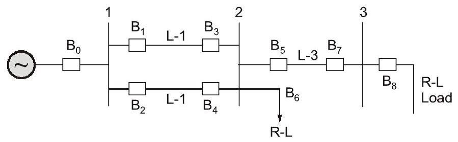
and are directional overcurrent relays blocking faults towards bus 2.


and are directional overcurrent relays blocking faults towards bus 2 and is directional overcurrent relay blocking faults towards bus 3.

and are directional overcurrent relays blocking faults towards Line 1 and Line 2, respectively, is directional overcurrent relay blocking faults towards ine 3 and is directional overcurrent relay blocking faults towards bus 2.

and are directional overcurrent relays blocking faults towards Line 1 and Line 2, respectively.
Sign in to see the solution
Log in to view the explanation, track your attempts, and keep your progress.
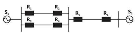
Sign in to UnlockA power system with two generators is shown in the figure below. The system (generators, buses and transmission lines) is protected by six over current relays to . Assuming a mix of directional and non directional relays at appropriate locations, the remote backup relays for are







Sign in to see the solution
Log in to view the explanation, track your attempts, and keep your progress.
Sign in to UnlockThe over current relays for the line protection and loads connected at the buses are shown in the figure.
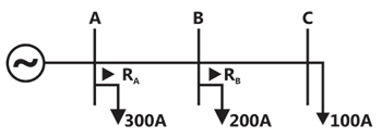
The relays are IDMT in nature having the characteristic

The maximum and minimum fault current at bus B are 2000A and 500A respectively. Assuming the time multiplier setting and plug setting for relay to be 0.1 and 5A respectively, the operating time of (in seconds) is _______________.

Sign in to see the solution
Log in to view the explanation, track your attempts, and keep your progress.
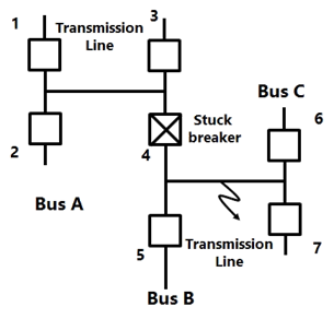
Sign in to UnlockConsider the protection system shown in the figure below. The circuit breakers, numbered from 1 to 7 are of identical type. A single line 10 ground fault with zero fault impedance occurs at the midpoint of the line (at point F), but circuit breaker 4 fails to operate ("stuck breaker"). If the relays are coordinated correctly, a valid sequence of circuit breaker operations is
Sign in to see the solution
Log in to view the explanation, track your attempts, and keep your progress.
Sign in to UnlockIn an inverse definite minimum time, electromagnetic type over-current relay the minimum time feature is achieved because of
Sign in to see the solution
Log in to view the explanation, track your attempts, and keep your progress.
Sign in to UnlockIf the fault current is 2000A, the relay setting is 50% and CT ratio is 400:5, the plug setting multiplier will be
Sign in to see the solution
Log in to view the explanation, track your attempts, and keep your progress.
Sign in to UnlockThe distribution system shown in figure is to be protected by over current system of protection.
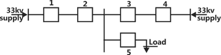
For proper fault discrimination directional over current relays will be required at locations
Sign in to see the solution
Log in to view the explanation, track your attempts, and keep your progress.
Sign in to Unlock