Network Analysis
Sinusoidal Steady State Analysis
Miscellaneous
Questions mapped to Miscellaneous under Sinusoidal Steady State Analysis.
3
Total0
Attempted0
Correct0
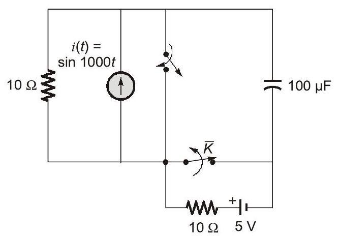
IncorrectThe circuit shown in the figure is initially in the steady state with the switch in open condition and in closed condition. The switch is closed and is opened simultaneously at the instant , where . The minimum value of in milliseconds, such that there is no transient in the voltage across the capacitor, is (Round off to 2 decimal places).






Sign in to see the solution
Log in to view the explanation, track your attempts, and keep your progress.
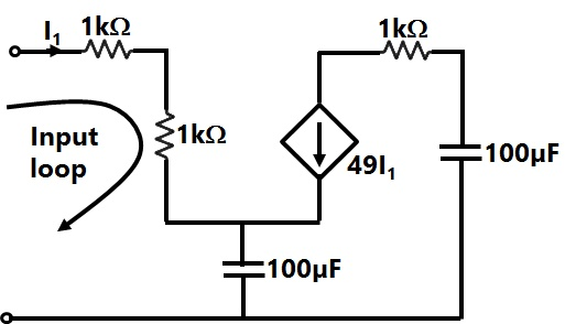
Sign in to UnlockThe equivalent capacitance of the input loop of the circuit shown is
Sign in to see the solution
Log in to view the explanation, track your attempts, and keep your progress.
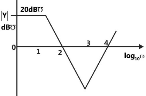
Sign in to UnlockA one port active network has an input admittance Y, the magnitude of which is shown in figure as a function of frequency. The circuit is resistive or capacitive in different frequency ranges.
Complete the following table:
Frequency Range | Type of Impedance | Value (Ω/H/F) |
10000 rad/sec < ω | A | P |
10 rad/sec < ω < 1000 rad/sec | B | Q |
Sign in to see the solution
Log in to view the explanation, track your attempts, and keep your progress.
Sign in to Unlock