Electrical Machines
Transformers
Equivalent Circuit - Transformer
Questions mapped to Equivalent Circuit - Transformer under Transformers.
16
Total0
Attempted0
Correct0
IncorrectA single-phase transformer is designed for use in India and rated 100 VA at 50 Hz . Later, this unit is shipped to the USA where it is used as a transformer at 60 Hz .


Which of the following statements is/are correct?
Sign in to see the solution
Log in to view the explanation, track your attempts, and keep your progress.
Sign in to UnlockIf an ideal transformer has an inductive load element at port 2 as shown in the figure below, the equivalent inductance at port 1 is
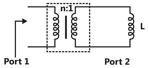
nL



Sign in to see the solution
Log in to view the explanation, track your attempts, and keep your progress.
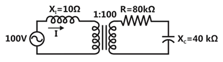
Sign in to UnlockThe following figure shows the connections of an ideal transformer with primary to secondary turns ratio of 1:100. The applied primary voltage is 100V (rms), 50Hz, AC. The rms value of the current I, in ampere, is ____________.
Sign in to see the solution
Log in to view the explanation, track your attempts, and keep your progress.
Sign in to UnlockThe self-inductance of the primary winding of a single phase, 50 Hz, transformer is 800 mH, and that of the secondary winding is 600 mH. The mutual inductance between these two windings is 480 mH. The secondary winding of this transformer is short circuited and the primary winding is connected to a 50 Hz, single phase, sinusoidal voltage source. The current flowing in both the windings is less than their respective rated currents. The resistance of both windings can be neglected. In this condition, what is the effective inductance (in mH) seen by the source?
Sign in to see the solution
Log in to view the explanation, track your attempts, and keep your progress.
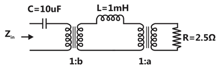
Sign in to UnlockFind the transformer ratios a and b such that the impedance ( ) is resistive and equals when the network is excited with a sine wave voltage of angular frequency of 5000 rad/s.


Sign in to see the solution
Log in to view the explanation, track your attempts, and keep your progress.
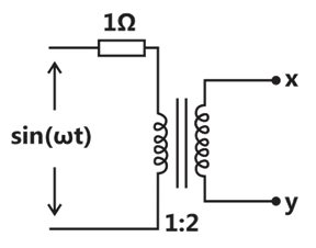
Sign in to UnlockAssuming an ideal transformer, the Thevenin’s equivalent voltage and impedance as seen from the terminals x and y for the circuit in figure are




Sign in to see the solution
Log in to view the explanation, track your attempts, and keep your progress.
Sign in to UnlockThe parameters measured for a 220V/110V, 50Hz, single-phase transformer are:
Self inductance of primary winding = 45mH
Self inductance of secondary winding = 30mH
Mutual inductance between primary and secondary windings = 20mH
using the above parameters, the leakage and magnetizing inductance as referred to primary side in the equivalent circuit respectively, are


Sign in to see the solution
Log in to view the explanation, track your attempts, and keep your progress.
Sign in to UnlockThe following arrangement consists of an ideal transformer and an attenuator which attenuates by a factor of 0.8. An ac voltage is applied across WX to get an open circuit voltage across YZ. Next, an ac voltage is applied across YZ to get an open circuit voltage across WX. Then, are respectively,






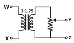
Sign in to see the solution
Log in to view the explanation, track your attempts, and keep your progress.
Sign in to UnlockA single-phase transformer has a turns ratio of 1:2 and is connected to a purely resistive load as shown in the figure. The magnetizing current drawn is 1 A, and the secondary current is 1 A. If core losses and leakage reactance are neglected, the primary current is
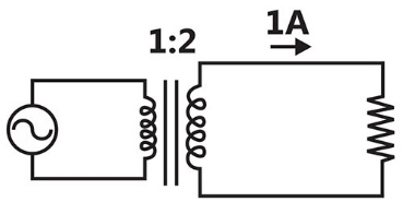
Sign in to see the solution
Log in to view the explanation, track your attempts, and keep your progress.
Sign in to UnlockIn the figure, transformer , has two secondary, all three windings having the same number of tums and with polarities as indicated. One secondary is shorted by a 10 Ω resistor R, and the other by a 15 µF capacitor. The switch SW is opened (t = 0) when the capacitor is charged to 5V with the left plate as positive. At t=0+ the voltage and current are



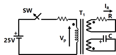
Sign in to see the solution
Log in to view the explanation, track your attempts, and keep your progress.
Sign in to UnlockThe equivalent circuit of a transformer has leakage reactance and magnetizing reactance . Their magnitudes satisfy






Sign in to see the solution
Log in to view the explanation, track your attempts, and keep your progress.
Sign in to UnlockThe resistance and reactance of a 100 kVA 11000/400V, Δ-Y distribution transformer are 0.02 and 0.07pu respectively. The phase impedance of the transformer referred to the primary is
Sign in to see the solution
Log in to view the explanation, track your attempts, and keep your progress.
Sign in to UnlockA single phase 6300kVA, 50 Hz, 3300V/400V distribution transformer is connected between two 50 Hz supply systems, A and B as shown in Figure, the transformer has 12 and 99 turns in the low and high voltage windings respectively. The magnetizing reactance of the transformer referred to the high voltage side is 500Ω. The leakage reactance of the high and low voltage windings are 1.0Ω and 0.012Ω respectively. Neglect the winding resistance and core losses of the transformer. The Thevenin voltage of system A is 3300V while that of system B is 400 V, the short circuit reactance of systems A and B are 0.5Ω and 0.010 Ω respectively. If no power is transferred between A and B, so that the two system voltages are in phase, find the magnetizing ampere turns of the transformer.

Sign in to see the solution
Log in to view the explanation, track your attempts, and keep your progress.
Sign in to UnlockA 3-phase transformer has rating of 20 MVA, 200 kV (star)–33 kV (delta) with leakage reactance of 12%. The transformer reactance (in ohms) referred to each phase of the L.V delta-connected side is
Sign in to see the solution
Log in to view the explanation, track your attempts, and keep your progress.
Sign in to UnlockIn a single-phase, three –winding transformer, the turns ratio for primary: secondary : tertiary windings is 20:4:1. With the lagging currents of 50A at a power factor of 0.6 in the tertiary winding, find the magnitude of primary current and power-factor.
Sign in to see the solution
Log in to view the explanation, track your attempts, and keep your progress.
Sign in to UnlockA 10kVA, 400 V/200V single-phase transformers with 10% impedance draws a steady short circuit line current of
Sign in to see the solution
Log in to view the explanation, track your attempts, and keep your progress.
Sign in to Unlock