Electrical Machines
Transformers
Induced EMF - Transformer
Questions mapped to Induced EMF - Transformer under Transformers.
21
Total0
Attempted0
Correct0
IncorrectWhich one of the following options represents possible voltage polarities in a single phase two winding transformer? Here, is the applied primary voltage, is the induced primary voltage, is the open circuit secondary voltage, and is the induced secondary voltage.




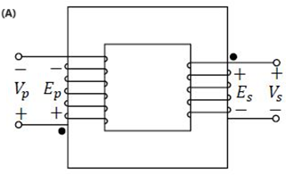
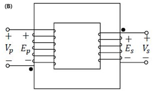
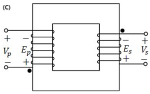
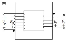
Sign in to see the solution
Log in to view the explanation, track your attempts, and keep your progress.
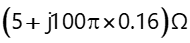
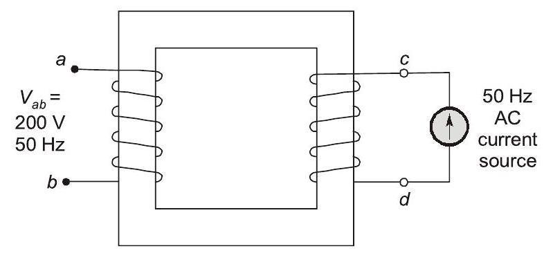
Sign in to UnlockWhen the winding of the single-phase, , two winding transformer is supplied from an AC current source of frequency , the rated voltage of (rms), is obtained at the open-circuited terminals . The cross sectional area of the core is and the average core length traversed by the mutual flux is . The maximum allowable flux density in the core is and the relative permeability of the core material is 5000. The leakage impedance of the winding and winding at are and , respectively. Considering the magnetizing characteristics to be linear and neglecting core loss, the self-inductance of the winding a-b in millihenry is _________ (Round off to 1 decimal place).








Sign in to see the solution
Log in to view the explanation, track your attempts, and keep your progress.
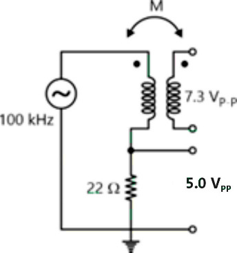
Sign in to UnlockAn air-core radio-frequency transformer as shown has a primary winding and a secondary winding. The mutual inductance M between the windings of the transformer is __________ μH. (Round off to 2 decimal places.)
Sign in to see the solution
Log in to view the explanation, track your attempts, and keep your progress.
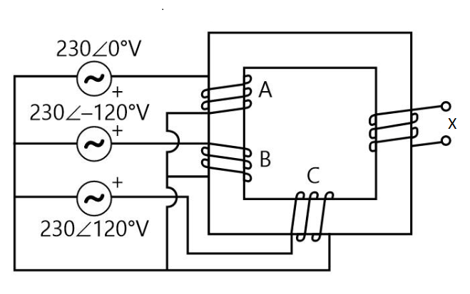
Sign in to UnlockWindings 'A', 'B' and 'C' have 20 turns each and are wound on the same iron core as shown, along with winding 'X which has 2 turns. The figure shows the sense (clockwise/anti-clockwise) of each of the windings only and does not reflect the exact number of turns, If windings 'A', 'B' and 'C' are supplied with balanced 3 -phase voltages at 50 Hz and there is no core saturation, the no-load RMS voltage (in V, rounded off to 2 decimal places) across winding ' X is ____________
Sign in to see the solution
Log in to view the explanation, track your attempts, and keep your progress.
Sign in to UnlockThe primary mmf is least affected by the secondary terminal conditions in a
Sign in to see the solution
Log in to view the explanation, track your attempts, and keep your progress.
Sign in to UnlockFor a specified input voltage and frequency, if the equivalent radius of the core of a transformer is reduced by half, the factor by which the number of turns in the primary should change to maintain the same no load current is
Sign in to see the solution
Log in to view the explanation, track your attempts, and keep your progress.
Sign in to UnlockA single-phase air core transformer, fed from a rated sinusoidal supply, is operating at no load. The steady state magnetizing current drawn by the transformer from the supply will have the waveform
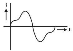
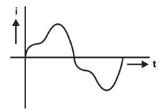
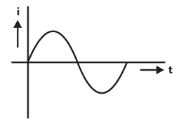
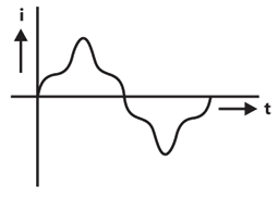
Sign in to see the solution
Log in to view the explanation, track your attempts, and keep your progress.
Sign in to Unlock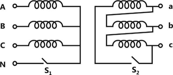
With both S1 and S2 open, the core flux waveform will be
Sign in to see the solution
Log in to view the explanation, track your attempts, and keep your progress.
Sign in to UnlockWith S2 closed and S1 open, the current waveform in the delta winding will be
Sign in to see the solution
Log in to view the explanation, track your attempts, and keep your progress.
Sign in to Unlock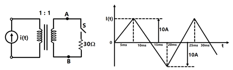
The circuit diagram shows a two-winding, loss less transformer with no leakage flux, excited from a current source, i(t), whose waveform is also shown. The transformer has a magnetizing inductance of 400/π mH.
The peak voltage across A and B, with S open is
Sign in to see the solution
Log in to view the explanation, track your attempts, and keep your progress.
Sign in to UnlockThe circuit diagram shows a two-winding, loss less transformer with no leakage flux, excited from a current source, i(t), whose waveform is also shown. The transformer has a magnetizing inductance of 400/π mH.
If the waveform of i(t) is changed to , the peak voltage across A and B with S closed is

Sign in to see the solution
Log in to view the explanation, track your attempts, and keep your progress.
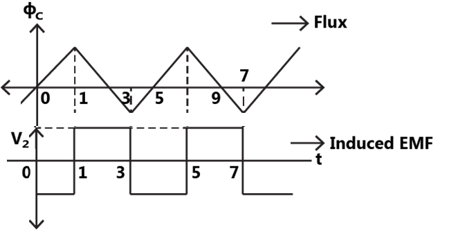
Sign in to UnlockThe core of a two-winding transformer is subjected to a magnetic flux variation as indicated in the figure.
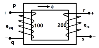
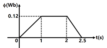
The induced emf in the secondary winding as a function of time will be of the form

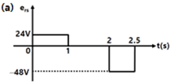
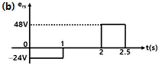
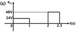
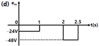
Sign in to see the solution
Log in to view the explanation, track your attempts, and keep your progress.
Sign in to UnlockFigure shows an ideal single-phase transformer. The primary and secondary coils are wound on the core as shown. Turns ratio . The correct phasors of voltages currents and core flux φ are as shown in



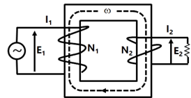
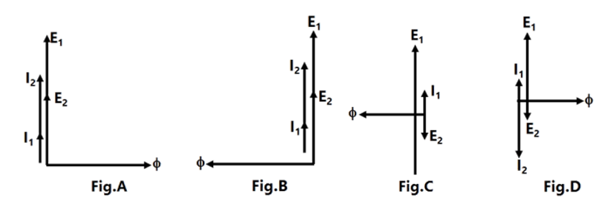
Sign in to see the solution
Log in to view the explanation, track your attempts, and keep your progress.
Sign in to UnlockA 1 kVA, 230V/100V, single phase, 50 Hz transformer having negligible winding resistance and leakage inductance is operating under saturation, while 250 V, 50 Hz sinusoidal supply is connected to the high voltage winding. A resistive load is connected to the low voltage winding which draws rated current. Which one of the following quantities will not be sinusoidal?
Sign in to see the solution
Log in to view the explanation, track your attempts, and keep your progress.
Sign in to UnlockA single-phase transformer is to be switched to the supply to have minimum inrush current. The switch should be closed be
Maximum supply voltage
Zero supply voltage
maximum supply voltage

maximum supply voltage

Sign in to see the solution
Log in to view the explanation, track your attempts, and keep your progress.
Sign in to UnlockThe core flux of a practical transformer with a resistive load
Sign in to see the solution
Log in to view the explanation, track your attempts, and keep your progress.
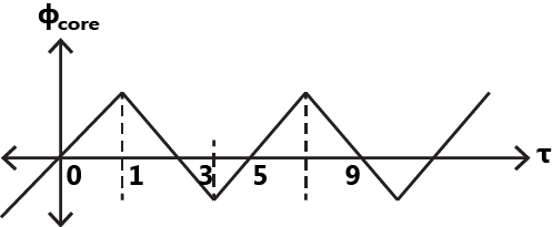
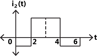
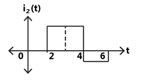
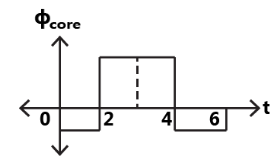
Sign in to UnlockAn ideal transformer has a linear B-H characteristic with a finite slope and a turns ratio 1:1. The primary of the transformer is energized with an ideal current source, producing the signal I as shown in figure. Sketch the shape (neglecting the scale factor) of the following signals, labeling the time axis clearly:
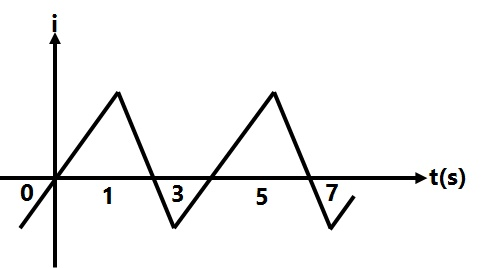
(a) The core flux with the secondary of the transformer open
(b) The open-circuited secondary terminal voltage
(c) The short-circuited secondary current
(d) The core flux with the secondary of the transformer short-circuited.




(a)
(b)
(c)
(d)
(a)
(b)
(c)
(d)
(a)
(b)
(c)
(d)
None
Sign in to see the solution
Log in to view the explanation, track your attempts, and keep your progress.
Sign in to UnlockThe magnetizing current in a transformer is rich in
harmonic

harmonic

harmonic

harmonic

Sign in to see the solution
Log in to view the explanation, track your attempts, and keep your progress.
Sign in to UnlockThe low voltage winding of a 400/230V, 1-phase, 50Hz transformer is to be connected to a 25Hz supply, the supply voltage should be
Sign in to see the solution
Log in to view the explanation, track your attempts, and keep your progress.
Sign in to UnlockA voltage v=400sin(314.16t) is applied to a 1-phase transformer on no-load. If the no load current of the transformer is 2sin(314.16t-85°), then magnetization branch impedance will be approximately equal to




Sign in to see the solution
Log in to view the explanation, track your attempts, and keep your progress.
Sign in to UnlockA 220/440 V, 50 Hz, 5 kVA single phase transformer operates on 220V, 40 Hz supply with secondary winding. Then
Sign in to see the solution
Log in to view the explanation, track your attempts, and keep your progress.
Sign in to Unlock